PC7821A-12CD中文资料
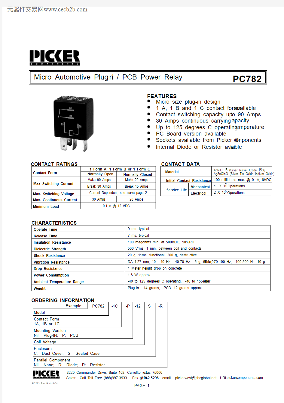
Micro Automotive Plug I n / PCB Power Relay
FEATURES
Micro size plug-in design
1 A, 1 B and 1 C contact forms available 30 Amps continuous carrying c apacity
Contact switching capacity up to 90 Amps Up to 125 degrees C operating temperature PC Board version available
PC782
Max. Switching Voltage Current Dependent, see curve page 21 Form A, 1 Form B or 1 Form C CONTACT RATINGS
CHARACTERISTICS
Operate Time 9 ms. typical Release Time Insulation Resistance 7 ms. typical
100 megohms min, at 500VDC, 50%RH Dielectric Strength 500 Vrms, 1 min. between coil and contacts Shock Resistance 20 g, 11ms, functional; 200 g, destructive
Vibration Resistance DA 1.27 mm, 10 - 40 Hz; 40-70 Hz: 5 g; DA 0.5mm, 70-100 Hz; 100-500 Hz: 10 g.Power Consumption 1.6 W approx.
Ambient Temperature Range -40 to 125 degrees C operating, -40 to 155 stor age Weight
Plug-In: 14 grams; PCB: 12 grams approx.
Sales: Call Toll Free (888)997-3933 Fax (818) 342-5296 email: pickerwest@https://www.360docs.net/doc/056517061.html, URL: https://www.360docs.net/doc/056517061.html,
3220 Commander Drive, Suite 102, Carrollton, T exas 75006
PC782 Rev B 4-13-04
PAGE 1
ORDERING INFORMATION
Example:
PC782Model -1C Sockets available from Picker C omponents Contact Form Parallel Component
-P CONTACT DATA
Material
Initial Contact Resistance Service Life
Mechanical Electrical
AgSnOInO (Silver Tin Oxide Indium Oxide)100 milliohms max @ 0.1A, 6VDC 1 X 10⁷
2 X 10⁵Operations Operations
Normally Open Nil: None; D: Diode; R: Resistor
Coil Voltage
-12Contact Form
Max Switching Current Break 30 Amps
Make 90 Amps 30 Amps
AgNiO 15 (Silver Nickel Oxide 15%)
Max. Continuous Current Minimum Load
0.1 A @ 12 VDC
S Drop Resistance 1 Meter height drop on concrete 1A, 1B or 1C Normally Closed Break 15 Amps
Make 20 Amps 20 Amps
Mounting Version Nil: Plug-IN; P: PCB -R
Internal Diode or Resistor avai lable
Enclosure
C: Dust Cover, S: Sealed Case
PC782
PC782
Sales: Call Toll Free (888) 997-3933 F ax (818) 342-5296 email: pickerwest@sbc https://www.360docs.net/doc/056517061.html, URL: https://www.360docs.net/doc/056517061.html,
3220 Commander Drive, Suite 102, Car rollton, Texas 75006
PAGE 2
(11.5)
.453(8.0).315(6.0)
.236(4.5)
.177(4.5).17730
878587a 86
(11.5)
.453(8.0).315(7.0)
.275(4.5)
.177(4.5).17730
878587a 86
(15.5)
.610(26.0)
1.02(23.0)
.906(0.8)
.032 Typ.(6.3)
.250Terms. 30 & 87
(12.0)
.472(4.8)
.189Terms. 85, 86 & 87a
(5.7)
.224(2.5)
.098(2.2)
.087Terms. 85, 86 & 87a
(2.5)
.098Terms. 30 & 87
87
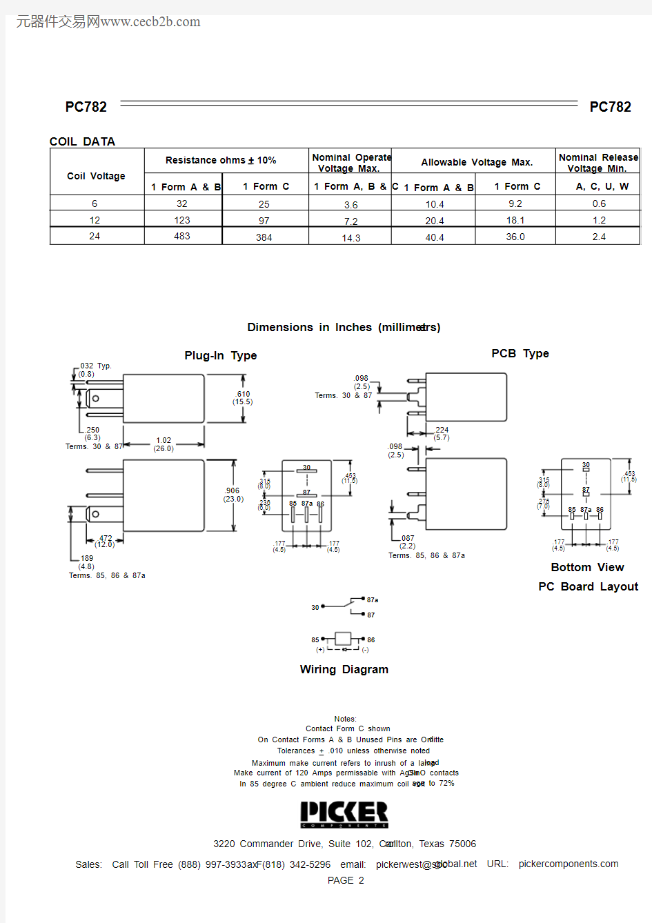
86Wiring Diagram
Tolerances +.010 unless otherwise noted
Notes:
Contact Form C shown
On Contact Forms A & B Unused Pins are Omitte d
Maximum make current refers to inrush of a lamp load
Make current of 120 Amps permissable with AgSn OInO contacts In 85 degree C ambient reduce maximum coil volt age to 72%
Dimensions in Inches (millimet ers)
Bottom View PC Board Layout
Plug-In Type
PCB Type