hayryn 等温淬火球墨铸铁生产
The Production of Austempered Ductile Iron (ADI)
Kathy L. Hayrynen
Applied Process Technologies Division, Livonia, MI
ABSTRACT
Austempered Ductile Iron (ADI) results from a specialty heat treatment of ductile cast iron. Strength improvements up to 100% (or more) in combination with excellent toughness can be realized by using this process.
Successful production of ADI requires a cooperative effort between the foundry and heat treater. High quality ductile iron is the necessary raw material. The proper heat treatment will then yield the desired mechanical properties.
INTRODUCTION
After several decades of successful production of Austempered Ductile Iron, the myth that a special type of ductile iron is needed still persists. In fact, the only necessary ingredient for the production of ADI is high quality ductile iron with the appropriate alloy content for hardenability, if needed.
This paper will review the austempering heat treat process and the foundry requirements that are necessary for the production of ADI.
BACKGROUND
The austempering process was first developed in the early 1930’s as a result of work that Bain, et al, was conducting on the isothermal transformation of steel. In the early 1940’s Flinn applied this heat treatment to cast iron, namely gray iron. In 1948 the invention of ductile iron was announced jointly by the British Cast Iron Research Association (BCIRA) and the International Nickel Company (INCO).
By the 1950’s, both the material, ductile iron, and the austempering process had been developed. However, the technology to produced ADI on an industrial scale lagged behind. The 1970’s would arrive before highly efficient semi-continuous and batch austempering systems were developed and the process was commercially applied to ductile iron.
By the 1990’s, ASTM A897-90 and ASTM A897M-90 Specifications for Austempered Ductile Iron Castings were published in the US while other specifications were developed worldwide. In addition, a new term to describe the matrix microstructure of ADI as “ausferrite”
was introduced.
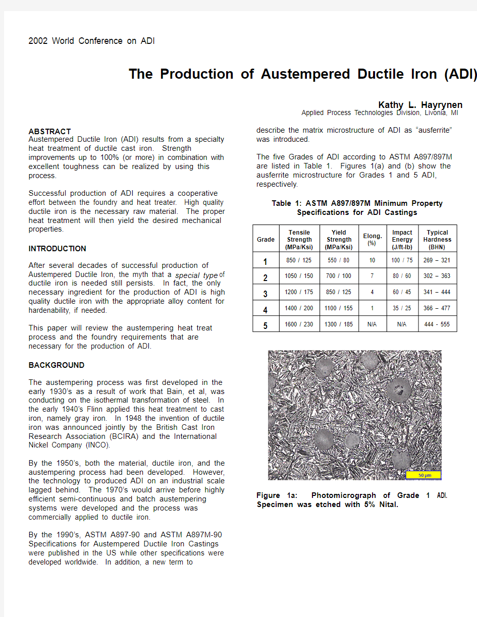
The five Grades of ADI according to ASTM A897/897M
are listed in Table 1. Figures 1(a) and (b) show the ausferrite microstructure for Grades 1 and 5 ADI, respectively.
Table 1: ASTM A897/897M Minimum Property
Specifications for ADI Castings
Grade
Tensile
Strength
(MPa/Ksi)
Yield
Strength
(MPa/Ksi)
Elong.
(%)
Impact
Energy
(J/ft-lb)
Typical
Hardness
(BHN)
1 850 / 125 550 / 80 10 100 / 75 269 – 321
2 1050 / 150 700 / 100 7 80 / 60 302 – 363
3 1200 / 175 850 / 125
4 60 / 4
5 341 – 444
4 1400 / 200 1100 / 15
5 1 35 / 25 36
6 – 477
5 1600 / 230 1300 / 185 N/A N/A 444 - 555
Figure 1a: Photomicrograph of Grade 1 ADI. Specimen was etched with 5% Nital.
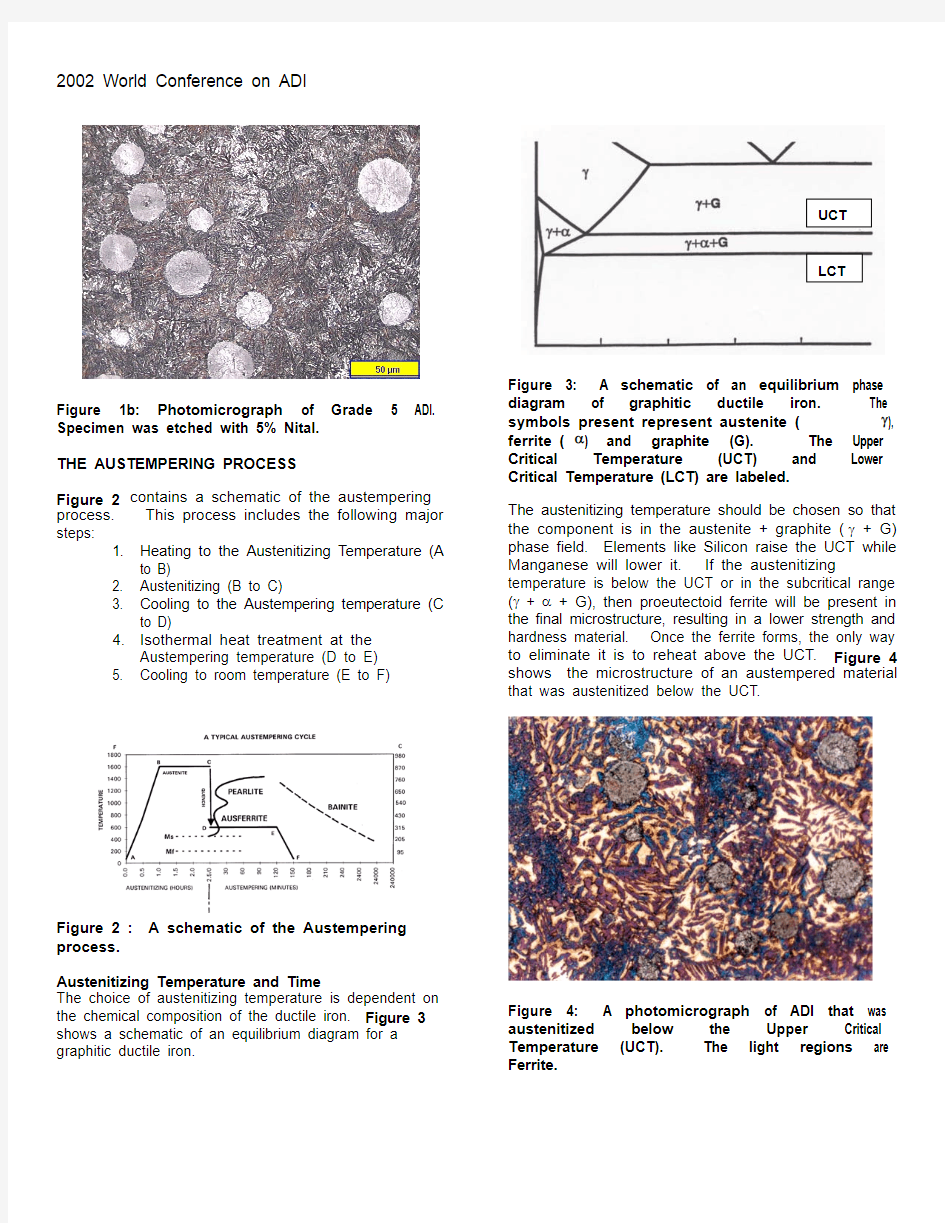
Figure 1b: Photomicrograph of Grade 5 ADI. Specimen was etched with 5% Nital. Figure 3: A schematic of an equilibrium phase diagram of graphitic ductile iron. The symbols present represent austenite (γ), ferrite (α) and graphite (G). The Upper Critical Temperature (UCT) and Lower Critical Temperature (LCT) are labeled.
THE AUSTEMPERING PROCESS
Figure 2 contains a schematic of the austempering process. This process includes the following major steps:
1. Heating to the Austenitizing Temperature (A
to B)
2. Austenitizing (B to C)
3. Cooling to the Austempering temperature (C
to D)
4. Isothermal heat treatment at the
Austempering temperature (D to E)
5. Cooling to room temperature (E to F)
Figure 2 : A schematic of the Austempering process.
Austenitizing Temperature and Time
The choice of austenitizing temperature is dependent on the chemical composition of the ductile iron. Figure 3 shows a schematic of an equilibrium diagram for a graphitic ductile iron.
UCT
LCT
The austenitizing temperature should be chosen so that the component is in the austenite + graphite (γ + G) phase field. Elements like Silicon raise the UCT while Manganese will lower it. If the austenitizing temperature is below the UCT or in the subcritical range (γ + α + G), then proeutectoid ferrite will be present in the final microstructure, resulting in a lower strength and hardness material. Once the ferrite forms, the only way to eliminate it is to reheat above the UCT. Figure 4 shows the microstructure of an austempered material that was austenitized below the UCT.
Figure 4: A photomicrograph of ADI that was austenitized below the Upper Critical Temperature (UCT). The light regions are Ferrite.
The time at the austenitizing temperature is equally as important as the choice of temperature. The ductile iron components should be held for a time sufficient to create an austenite matrix that is saturated with carbon. This time is additionally affected by the alloy content of the ductile iron with heavily alloyed material taking longer to austenitize.
Cooling to the Austempering Temperature
Cooling from the austenitizing temperature to the austempering temperature (as shown from C to D in Figure 2) must be completed rapidly enough to avoid the formation of pearlite. If pearlite is formed, the strength, elongation and toughness will be reduced. Figure 5 shows a photomicrograph of Grade 2 ADI that contains pearlite.
Figure 5: Pearlite (dark constituent) in Ausferrite.
The formation of pearlite can be caused by several things, most notably a lack of quench severity or a low hardenability for the effective section size. It is possible to increase the quench severity of molten salt quench bathes by making water additions. Oil quench equipment is limited to the production of Grade 5 ADI because of the quench temperatures necessary to produce Grades 4 and higher.
The alloy content in ADI is necessary for hardenability purposes or the austemperability of the ductile iron. In general, section sizes greater than 19 mm or 0.75 inches require an alloy addition. Typically, a foundry will work closely with the heat treater to determine the optimum chemical composition of the ductile iron to be austempered.
Figure 6 shows a schematic of how the alloying elements segregate in ductile iron during solidification.
Figure 6: A Schematic showing the Segregation of Alloying Elements in Ductile Iron during Solidification
The alloying elements that are typically added for hardenability purposes include: Cu, Ni and Mo. Manganese additions are not recommended because of
the tendency of Mn to segregate to the regions in between the graphite nodules. Manganese delays the austempering reaction, which can result in the formation
of martensite due to the presence of low carbon austenite.
Copper additions are often initially recommended because of price considerations. However, more is not necessarily better when Cu additions are considered. Levels in excess of 0.80 can create diffusion barriers around the graphite nodules and inhibit carbon diffusion
during austenitizing.
Nickel additions are made when the level of Cu has
been maximized. Ni additions of up to 2 % are typically made. Beyond that, the price becomes an important consideration. Lastly, Molybdenum is a potent hardenability agent. Unfortunately, it segregates highly
to the intercellular/interdendritic locations between the graphite nodules. Molybdenum is a strong carbide former. Figure 7 contains a photomicrograph of Molybdenum carbides that were present in ADI with a
Mo addition. The formation of Mo carbides is undesirable, especially if a component is to be machined
after heat treatment.
Figure 7: Molybdenum carbides (white) in ADI.
Recommendations for alloying ADI are summarized in
Table 2.
Table 2: Recommendations for Alloying ADI
Recommended Limit
(wt pct)
Manganese Max section > 13mm 0.35 max
Max section < 13 mm 0.60 max
Copper 0.80 max – only as needed
Nickel 2.00 max – only as needed
Molybdenum 0.30 max – only as needed
Choice of Austempering (Quench) Temperature and Time The choice of austempering temperature and time is dependent on the final properties desired. The typical temperature ranges utilized are 460 – 750°F (or 238 - 399°C). The lower grades (1 and 2) require temperature choices at the upper end of the range while the higher grades are produced at lower quench temperatures. Time at temperature is dependent on the choice of temperature as well as the alloy content. For example, Grade 1 ADI will transform faster than Grade 5 as the quench temperature is approximately 200°F (93°C) higher.
The components are held for a sufficient time at temperature for ausferrite to form. Ausferrite consists of ferrite in a high carbon, stabilized austenite. If held for long time periods, the high carbon austenite will eventually undergo a transformation to bainite, the two phase ferrite and carbide (α. + Fe 3C). In order for this transformation to occur, longer periods of time are typically needed – much longer than would be economically feasible for the production of ADI.
Once the ausferrite has been produced, the components are cooled to room temperature. The cooling rate will not affect the final microstructure as the carbon content of the austenite is high enough to lower the martensite start temperature to a temperature significantly below room temperature.
FOUNDRY CONSIDERATIONS FOR THE PRODUCTION OF ADI
The austempering process creates a product that is stronger than conventional grades of ductile iron. As a result, it is more sensitive to any defects that could be present in the base ductile iron. Austempering is NOT a cure for poor quality iron. Rather, the effects of the
slightest defects on the mechanical properties of ductile iron become magnified as a result of austempering. Thus, the toughness of an ADI component can be severely compromised by the presence of non-metallic inclusions, carbides, shrink and dross even if their levels were acceptable for conventional ductile iron. There is no “one” optimum recipe for ductile iron that is to be austempered. However, high quality is imperative in all
cases.
Nodule Count and Nodularity
The recommended minimums for nodule count and
nodularity for ductile iron to be austempered are as
follows:
Nodule Count 100/mm 2 ( with a uniform
distribution) Nodularity 85% Nodule count is especially important when alloy additions are made. Low nodule counts lead to larger spacing between the graphite nodules and larger regions of segregation (Note Figure 6.). In the worst case scenario, these regions can become so heavily segregated that they do not fully transform during austempering, resulting in the formation of low carbon austenite or even martensite. Figure 8 shows regions of segregation that did not transform during austempering. Higher nodule counts will break up the segregated regions shown in Figure 8.
Figure 8: Segregated regions (white) with a high Mn content in ADI.
Casting Quality
Castings to be austempered should be free of non-metallic inclusions, carbides, shrink and porosity. In order to achieve the property minimums in Table 1, the following levels should be maintained.
Carbides + Nonmetallic inclusions - maximum 0.5%
Porosity and/or Microshrinkage – maximum 1% Carbon Equivalent
The Carbon Equivalent (CE = %C + 1/3 %Si) should be controlled to produce sound castings. General Guidelines are provided in Table 3.
Table 3: Carbon Equivalent Guidelines for the Production of ADI
Section Size CE Range
0 – 0.5 inches ( 0 – 13 mm) 4.4 – 4.6
0.5 – 2 inches (13 – 51 mm) 4.3 – 4.6
Over 2 inches (51 mm) 4.3 – 4.5
Chemical Composition
The chemical composition ranges for a component should initially be established between the foundry and the heat treater. The amount of alloy (if needed) will be a function of the alloy in the foundry’s base metal, the part configuration (section size and shape) and the austempering equipment that is used. Suggested chemistry targets along with typical control ranges are listed in Table 4. Table 4: Suggested Targets and Typical Control Ranges for the Production of ADI
Element Suggested
Target
Typical
Control
Range Carbon – C 3.6% ± 0.20% Silicon – Si 2.5% ± 0.20% Magnesium – Mg (%S x 0.76)+0.025% ± 0.005% Manganese – Mn
Max section > 13 mm
Max section < 13 mm
0.35% maximum
0.60% maximum
± 0.05%
Copper – Cu 0.80% maximum
(only as needed)
± 0.05%
Nickel – Ni 2.00% maximum
(only as needed)
± 0.10%
Molybdenum - Mo 0.30% maximum
(only as needed)
± 0.03%
Tin - Sn 0.02% maximum
(only as needed)
±0.003%
Antimony – Sb 0.002% maximum
(only as needed)
±0.0003% Phosphorus – P 0.04% maximum
Sulfur – S 0.02% maximum
Oxygen – O 50 ppm maximum
Chromium – Cr 0.10% maximum
Titanium – Ti 0.040% maximum
Vanadium – V 0.10% maximum
Aluminum – Al 0.050% maximum
Arsenic – As 0.020% maximum
Bismuth – Bi 0.002% maximum
Boron – B 0.002% maximum
Cadmium – Cd 0.005 maximum
Lead – Pb 0.002% maximum
Selenium – Se 0.030% maximum
Tellurium – Te 0.020% maximum
Once chemical composition ranges have been established between the foundry and the heat treater, it is important for the foundry to produce ductile iron within the established ranges. Wide variations in chemical composition can lead to variations in the pearlite/ferrite ratio in the as-cast ductile iron as well as a need to adjust the heat treatment parameters. The response or growth during austempering is a function of the prior microstructure and the austempering temperature. Figure 9 shows the linear dimensional change as a function of austempering temperature for ADI with prior microstructures of ferrite, pearlite and a ferrite/pearlite mix.
Figure 9: Linear Dimensional Change as a function of Austempering Temperature for various prior microstructures. 4. Kovacs, B. V., “ADI – Fact and Fiction”, Modern Casting, March 1990, pp. 38-41.
Figure 9 shows that the growth is different for pearlite or ferrite. However, the growth is consistent from one heat treat lot to another if the chemical composition ranges are obeyed. End users use the consistent growth of ADI to their advantage. Components can be designed to be machined prior to heat treatment and then grow to size during austempering.
SUMMARY
The production of ADI is not a highly complicated process. Any foundry that works in conjunction with a heat treater can conceivably make ADI. However, there are important considerations in order to be successful. High quality ductile iron with the proper alloy content is the necessary ingredient. Remember that austempering is not the cure for poor quality as it will make bad iron even worse.
Knowledgeable heat treaters will work with a foundry to establish the proper chemical composition of the ductile iron to be austempered. The proper choice of heat treatment parameters will then lead to the successful production of any grade of ADI. ACKNOWLEDGMENTS
The author would like to thank the following individuals for their assistance in putting this paper together: Kristin Brandenberg, Terry Lusk, and John Keough. The support of the employees of Applied Process, Applied Process Technologies Division, AP Westshore and AP Southridge are also noted.
A special thank you to Dr. Karl Rundman and Dennis Moore for the introduction to metal castings and ADI. Their enthusiasm and encouragement over the past 15 years has been sincerely appreciated.
Lastly, the author would like to acknowledge the late Dr. Bela Kovacs for the invaluable contributions he made to the ADI world and for being a great mentor and friend. REFERENCES
1. Hayrynen, K.L., “ADI: Another Avenue for Ductile Iron Foundries”, Modern Casting, August 1995, pp. 35-37.
2. Section IV, Ductile Iron Data for Design Engineers, published by Rio Tinto Iron & Titanium Inc, 1990.
3. Foundry Requirements for the Production of ADI – Internal Information, Applied Process Inc. ADDITIONAL RESOURCES
+ Websites
https://www.360docs.net/doc/018228282.html,
https://www.360docs.net/doc/018228282.html,/didata
https://www.360docs.net/doc/018228282.html,
https://www.360docs.net/doc/018228282.html,
https://www.360docs.net/doc/018228282.html,
金相实验报告
金相实验报告 篇一:金相实验报告 广州大学机械与电气工程学院 课程报告 报告题目: 金相实验报告 专业班级:机械111 姓名:邓永明 学号: 1107XX14 组别:第六组 指导老师:胡一丹 完成日期: XX.10.18 一. 热处理工艺分析 1. 正火 (1)工艺内容:正火(英文名称:normalizing),又称常化,是将工件加热至Ac3(A 是指加热时自由铁素体全部转变为奥氏体的终了温度,一般是 从727℃到912℃之间)或Acm(Acm是实际加热中过共析钢完全 奥氏体化的临界温度线 )以上30~50℃,保温一段时间后,从 炉中取出在空气中或喷水、喷雾或吹风冷却的金属热处
理工艺。 其目的是在于使晶粒细化和碳化物分布均匀化。根本目的是去 除材料的内应力、降低材料的硬度为接下来的加工做准备。 (2)工艺特点:正火主要用于钢铁工件。一般钢铁正火与退火相似,但冷却速 度稍大,组织较细。有些临界冷却速度很小的钢,在空气中冷 却就可以使奥氏体转变为马氏体,这种处理不属于正火性质, 而称为空冷淬火。与此相反,一些用临界冷却速度较大的钢制 作的大截面工件,即使在水中淬火也不能得到马氏体,淬火的 效果接近正火。钢正火后的硬度比退火高。正火时不必像退火 那样使工件随炉冷却,占用炉子时间短,生产效率高,所以在 生产中一般尽可能用正火代替退火。对于含碳量低于0.25%的 低碳钢,正火后达到的硬度适中,比退火更便于切削加
工,一 般均采用正火为切削加工作准备。对含碳量为0.25~0.5%的中 碳钢,正火后也可以满足切削加工的要求。对于用这类钢制作 的轻载荷零件,正火还可以作为最终热处理。高碳工具钢和轴 承钢正火是为了消除组织中的网状碳 化物,为球化退火作组织 准备。正火与退火的不同点是正火冷却速度比退火冷却速度稍 快,因而正火组织要比退火组织更细一些,其机械性能也有所 提高。另外,正火炉外冷却不占用设备,生产率较高,因此生 产中尽可能采用正火来代替退火。对于形状复杂的重要锻件, 在正火后还需进行高温回火(550-650℃)高温回火的目的在于 消除正火冷却时产生的应力,提高韧性和塑性。 正火后的组织:亚共析钢为F+S,共析钢为S,过共析钢为S+
球墨铸铁的热处理
球墨铸铁的热处理 目前球墨铸铁所采用的热出库工艺有:消除内应力的低温退火;高温石墨化退火;低温石墨化退火;正火与回火;淬火与回火;等温淬火等。球墨铸铁的表面淬火正在扩大应用。对球墨铸铁的化学热处理也在研究应用。 1 球墨铸铁消除内应力的低温退火 球墨铸铁与灰口铸铁比较,容易产生较高的内应力,一般高1-2倍,与白口铸铁的内应力差不多。 消除内应力低温退火的工艺过程是:将铸铁加热到Ac1以下某一温度,保温一段时间,然后随炉缓慢冷却使铸铁完全过渡到稳性温度范围,至200-250℃即出炉空冷。 球墨铸铁消除内应力的倾向性与金属基体有关,珠光体球墨铸铁比铁素体基体为小。例如当退火温度为600℃时,对于珠光体+铁素体和铁素体基体的球墨铸铁保温15小时后可完全消除内应力。而对于珠光体基体的球墨铸铁,要完全消除内应力保温时间长达63小时。但都比钢的消除倾向大。 在保温的前2-3小时内消除内应力的效果最为显著。退火温度愈高,则内应力消除的愈快,愈安全。 目前工厂一般按下述工艺进行:加热速度控制在60-120℃/小时的范围内。避免产生新的内应力。加热温度一般控制在550-650℃之间。对于珠光体基体的球墨铸铁,考虑到当加热温度超过600℃后,可能发生共析渗碳体的石墨化和粒化。所以加热温度适当降低为550-620℃为宜。保温时间为2-8小时。然后随炉缓冷(冷却速度为30-60℃/小时)至200-250℃出炉空冷。采用该工艺退火,可消除铸件中残余应力之90-95%。 2球墨铸铁的高温石墨化退火
球墨铸铁具有较大的向心倾向性。在生产过程中常常由于化学成分选择不当,球化剂加入量过多或孕育剂量不足而造成铸件中出项大量的奥氏体或自由渗碳体;有时由于球墨铸铁中磷量过高或磷的严重偏析倾向,甚至在含磷量为0.05%时就会出现磷共晶。当自由渗碳体和磷共晶总量超过3%时,就使铸件的机械性能变坏,加工困难。在这种情况下就必须采用高温石墨化的方法来予以消除。球墨铸铁高温石墨化退火的工艺是:将铸铁件加热至Ac3+(30-50℃),保温一段时间进行第一阶段石墨化,然后根据对球墨铸铁基体要求的不同采用不同的冷却方式。加热温度一般为900-960℃。保温时间一般为1-4小时。 高温石墨化以后的冷却,则是根据对球墨铸铁基体的组织要求而定。如果要求获得高韧性的铁素体基体,则在高温保温待第一阶段石墨化完成后,随炉冷却到720-760℃保温进行第二阶段石墨化,以后再炉冷至600℃出炉空冷;也可以直接从高温缓慢冷却通过共析转变温度范围至600℃时出炉空冷,使奥氏体在缓慢冷却过程中直接分解为铁素体及石墨。这时球墨铸铁组织为铁素体+球状石墨。如果要求基体为珠光体,则高温保温后即出炉进行空冷。这时铸铁组织为索氏体型珠光体+少量片状铁素体〔<10%〕+球状石墨。
球墨铸铁汽车曲轴的加工工艺解读
球墨铸铁汽车曲轴的加工工艺 学院机电工程学院 专业机械类 年级班别创新实验班12(1) 学号 3112010453 3112010454 3112010455 3112010462 学生姓名罗毓健骆智伟 马欣华冼文飞 指导教师王成勇 2014年 6 月
摘要 球墨铸铁具有优良的机械性能,已经大量用于制造强度、韧性、耐磨性要求较高的零件。球墨铸铁大量地应用于汽车发动机曲轴的加工生产,结合球墨铸铁的特性,本文讲述了球墨铸铁应用于曲轴的切削与磨削加工机理及其加工工艺,介绍了聚晶立方氮化硼(PCBN)刀具切削加工等温淬火球墨铸铁(ADI)时的特征。介绍了奇瑞公司曲轴的加工工艺以及几款相关的曲轴专用加工机床。 关键词:球墨铸铁,曲轴,ADI,PCBN
目录 1球墨铸铁基本性质与应用 (1) 1.1 球墨铸铁的成分与组织结构 (1) 1.2 球墨铸铁的机械、物理、力学性能 (1) 1.3 典型零件、应用场合 (2) 1.4 球墨铸铁曲轴加工批量和加工质量要求 (2) 1.5 小结 (2) 2球墨铸铁切削与磨削加工机理 (2) 2.1 等温淬火球墨铸铁(ADI)的切削与磨削可加工性简述 (3) 2.2 铸铁应用于曲轴的主要切削、磨削去除过程 (3) 2.3 球墨铸铁的切削加工过程特征 (4) 2.4 加工等温淬火球墨铸铁常用刀具 (5) 2.5 曲轴加工工艺 (6) 3曲轴加工专用机床 (12) 3.1 曲轴质量定心机 (13) 3.2 数控车-车拉机床 (13) 3.3 曲轴圆角滚压机床 (13) 3.4 绿色粗磨“扒皮”机床 (13) 参考文献 (14)
金属材料及热处理实验报告
金属材料及热处理实验报告 学院:高等工程师学院 专业班级:冶金E111 姓名:杨泽荣 学号: 41102010 2014年6月7日
45号钢300℃回火后的组织观察及洛氏硬度测定 目录 一、实验目的 (1) 二、实验原理 (1) 1.加热温度的选择 (1) 2.保温时间的确定 (2) 3.冷却方法 (3) 三、实验材料与设备 (4) 1.实验材料 (4) 2.实验设备 (4) 四、实验步骤 (4) 1.试样的热处理 (4) 1.1淬火 (4) 1.2回火 (5) 2.试样硬度测定 (5) 3.显微组织观察与拍照记录 (5) 3.1样品的制备 (5) 3.2显微组织的观察与记录 (6) 五、实验结果与分析 (6) 1.样品硬度与显微组织分析 (6) 2.淬火温度、淬火介质对钢组织和性能的影响 (6) 2.1淬火温度的影响 (6) 2.2淬火介质的影响 (7) 3回火温度对钢组织与性能的影响 (7) 3.1回火温度对45钢组织的影响 (7) 3.2回火温度对45 钢硬度和强度的影响 (7) 4合金元素对钢的淬透性、回火稳定性的影响 (8) 4.1合金元素对钢的淬透性的影响 (8) 4.2合金元素对钢的回火稳定性的影响 (9) 5碳含量对钢的淬硬性的影响 (9) 六、结论 (9) 参考文献 (9)
一、实验目的 1.掌握碳钢的常用热处理(淬火及回火)工艺及其应用。 2.研究加热条件、保温时间、冷却条件与钢性能的关系。 3.分析淬火及回火温度对钢性能的影响。 4.观察钢经热处理后的组织,熟悉碳钢经不同热处理后的显微组织及形态特征。 5.了解金相照相的摄影方法,培养学生独立分析问题和解决问题的能力。 二、实验原理 钢的热处理就是利用钢在固态范围内的加热、保温和冷却,以改变其内部组织,从而获得所需要的物理、化学、机械和工艺性能的一种操作。一般热处理的基本操作有退火、正火、淬火、回火等。 进行热处理时,加热温度、保温时间和冷却方式是最重要的三个基本工艺因素。正确选择这三者的规范,是热处理成功的基本保证。 1.加热温度的选择 1)退火加热温度一般亚共析钢加热至Ac3+(20—30)℃(完全退火);共析钢和过共析钢加热至Ac1 +(20—30)℃(球化退火),目的是得到球状渗碳体,降低硬度,改善高碳钢的切削性能。 2)正火加热温度一般亚共析钢加热至Ac3 +(30—50)℃;过共析钢加热至Accm +(30—50)℃,即加热到奥氏体单相区。退火和正火的加热温度范围选择见图2.1。 3)淬火加热温度一般亚共析钢加热至Ac3+(30—50)℃;共析钢和过共析钢加热至Ac1+(30—50)℃,见图2.2。 钢的成分,原始组织及加热速度等皆影响到临界点的位置。在各种热处理手册或材料手册中,都可以查到各种钢的热处理温度。热处理时不能任意提高加热温度,因为加热温度过高时,晶粒容易长大,氧化、脱碳和变形等都会变得比较严重。各种常用钢的工艺规范见表2.1。 4)回火温度的选择钢淬火后都要回火,回火温度决定于最终所要求的组织和性能(常常是根据硬度的要求)。按加热温度高低回火可分为三类:
淬火炉加工工艺【详解】
淬火炉加工工艺 内容来源网络,由深圳机械展收集整理! 以冷却形式的不同来划分淬火的种类,主要有单液淬火、双液淬火、分级淬火和等温淬火等。 (1)单液淬火。单液淬火是将奥氏体工件迅速浸入某一种淬火介质,一直冷到室温的淬火操作方法。单液淬火冷却介质的选择依据是:工件在该介质中的冷却速度必须大于此工件钢种的临界冷却速度,并应保证工件不会淬裂。单液淬火介质有水、盐水、碱水、油以及一些专门配制的淬火剂等。 (2)双液淬火。为了克服单液淬火的缺点,使工件的淬火冷却尽可能接近理想情况,可以将两种冷却能力不同的介质配合起来使用,即将加热后的工件先淬入第一种冷却能力大的介质中,待其冷至稍高于Ms温度(约300℃),然后立即转入第二种冷却能力较小的介质中冷至室温,这种淬火冷却方法称为双液淬火。 对于有些工件,为了进一步减慢Ms以下的冷速,也可采用水淬空冷或油淬空冷的方法,空气也可作为冷却介质来对待。 (3)分级淬火(马氏体分级淬火)。这种冷却方法的特点是先将工件浸入温度略高于Ms的浴槽,在浴槽中保温至工件表面与中心均冷至浴槽的温度,然后取出
空冷。浴槽温度一般为Ms+ (10~20)℃。浴槽中介质的成分采用硝盐浴、碱浴、中性盐浴。 (4)预冷淬火。淬火加热后,工件并不立即浸入冷却介质中,而是在空气中先进行短时间的冷却,待工件降至一定温度时,再浸入冷却介质,这种淬火方法称为预冷淬火或延迟淬火。 预冷淬火的关键是控制好预冷时间,预冷时间短则效果差;时间长则有可能使工件淬火硬度降低(发生非马氏体转变)。由于工件的材料各异,形状尺寸千差万别,同时还受出炉温度和环境温度的影响,故很难对预冷时间进行准确的计算,主要靠操作者的技术和经验来掌握。 (5)局部淬火。有的工件只要某个局部硬度较高,其他部位无硬度要求或要求硬度较低。这一情况一般可采用局部淬火法,即只对工件上某个局部进行淬火的方法。局部淬火的主要形式有两种,局部加热局部冷却法和整体加热局部冷却法。前者主要适用于盐浴炉加热时的工件,后者箱式炉、盐浴炉均可采用。 (6)冷处理。冷处理就是将淬火钢继续冷却到室温以下某一温度,使在室温尚未转变的残余奥氏体继续转变为马氏体的一种淬火后续操作。 对一些尺寸稳定性要求很高的零件,必须把淬火组织中的残余奥氏体减少到最低限度,使用过程中不致因形状和尺寸变化超出精度要求而失效。冷处理的目的就
高碳铬轴承钢贝氏体等温淬火.
高碳铬轴承钢贝氏体等温淬火 洛阳轴承研究所(河南洛阳471039张增歧刘耀中樊志强 洛阳轴承(集团公司(河南洛阳471039李丽霞 【ABSTRACT】On the base of study results in home and abroad,the mechanical performance of lower bainite of high carbon chromium bearing steels have been analyzed com paratively,the research on cause of surface residual stress and dimension expansion has been made,the advantage and application of bainite hardening technology in production have been illustrated. 自上世纪80年代开始,国内对G Cr15钢的贝 氏体淬火进行了大量基础研究,并开始应用在铁路货车轴承及轧机轴承的热处理。自90年代初开始,该贝氏体淬火工艺在轧机、机车、铁路客车等轴承上得到推广应用,尤其在轧机轴承和高速及准高速铁路轴承的生产上推广迅速,同时开发了适合于贝氏体淬火的新钢种G Cr18M o。 综合国内各研究成果可知,高碳铬轴承钢下贝氏体(以下简称B L 组织能提高钢的比例极限、屈服强度、抗弯强度和断面收缩率,与相同温度回火的马氏体(以下简称M组织相比,具有更高的冲击韧度、断裂韧度、耐磨性及尺寸稳定性,表面应力状态为压应力,但高碳铬轴承钢贝氏体淬火对接触疲劳寿命的影响尚缺乏统一认识,对表面 压应力形成原因和B L 淬火轴承零件尺寸涨大原因也缺乏深入研究。本文根据以往的研究成果,
ASTM A897&A897M-2003 等温淬火球墨铸铁
Designation:A897/A897M–03 Standard Speci?cation for Austempered Ductile Iron Castings1 This standard is issued under the?xed designation A897/A897M;the number immediately following the designation indicates the year of original adoption or,in the case of revision,the year of last revision.A number in parentheses indicates the year of last reapproval. A superscript epsilon(e)indicates an editorial change since the last revision or reapproval. 1.Scope 1.1This speci?cation covers ductile iron castings that are subsequently heat treated by an austempering process as de?ned in10.1. 1.2The application of the austempering heat treatment extends the range of properties achievable in ductile iron castings. 1.3No precise quantitative relationship can be stated be-tween the properties of the iron in various locations of the same casting or between the properties of castings and those of a test specimen cast from the same iron(see Appendix X1).How-ever,austempering heat treatment will tend to diminish any differences in mechanical properties. 1.4The production of castings,machining(if required),and the austempering heat treatments may be performed by differ-ent manufacturers,as covered in Section15.The purchaser should establish by contract agreement,at the time of ordering, the responsibility of the various parties for meeting the speci?cation requirements. 1.5The values stated in either inch-pound or SI units are to be regarded separately as standard.Within the text,the SI units are shown in brackets[].The values stated in each system are not exact equivalents;therefore,each system shall be used independently of the https://www.360docs.net/doc/018228282.html,bining values from the two systems may result in nonconformance with the speci?cation. 2.Referenced Documents 2.1ASTM Standards:2 A247Test Method for Evaluating the Microstructure of Graphite in Iron Castings A370Test Methods and De?nitions for Mechanical Testing of Steel Products A732Speci?cation for Castings,Investment,Carbon and Low Alloy Steel for General Application,and Cobalt Alloy for High Strength at Elevated Temperatures A834Speci?cation for Common Requirements for Iron Castings for General Industrial Use E8Test Methods for Tension Testing of Metallic Materials E10Test Methods for Brinell Hardness of Metallic Mate-rials E23Test Methods for Notched Bar Impact Testing of Metallic Materials 2.2Military Standard: MIL-STD-129Marking for Shipment and Storage3 3.Ordering Information 3.1Orders for material to this speci?cation shall include the following information: 3.1.1ASTM designation,with year of issue, 3.1.2Grade of austempered ductile iron required(see Table 1and Sections6and7), 3.1.3Chemical composition requirements,if any(see Sec-tion4), 3.1.4Heat treated microstructure restrictions(see Section 10), 3.1.5Test coupon criteria(see Section12), 3.1.6Lot size and tests per lot(see12.6and Section15), 3.1.7Special requirements,if desired,including hardness, radiographic soundness,magnetic particle inspection,pressure tightness,dimensions,or surface?nish(see Section9), 3.1.8Certi?cation,if required(see Section16), 3.1.9Special preparation for delivery,if required(see Sec-tion17). 4.Chemical Composition 4.1Although this speci?cation has no speci?c chemical requirements,such requirements may be agreed upon between the manufacturer,heat treater,and the purchaser. 5.Microstructure 5.1The graphite component of the microstructure shall consist of a minimum80%spheroidal graphite conforming to Types I and II per Test Method A247. 1This speci?cation is under the jurisdiction of ASTM Committee A04on Iron Castings and is the direct responsibility of Subcommittee A04.02on Malleable and Ductile Iron Castings. Current edition approved Dec.1,2003.Published January2004.Originally approved https://www.360docs.net/doc/018228282.html,st previous edition approved in2002as A897-02. 2For referenced ASTM standards,visit the ASTM website,https://www.360docs.net/doc/018228282.html,,or contact ASTM Customer Service at service@https://www.360docs.net/doc/018228282.html,.For Annual Book of ASTM Standards volume information,refer to the standard’s Document Summary page on the ASTM website. 3Available from Standardization Documents,Order Desk,Building4,Section D, 700Robbins Ave.,Philadelphia,PA19111-5098,Attn:NPODS. 1 Copyright?ASTM International,100Barr Harbor Drive,PO Box C700,West Conshohocken,PA19428-2959,United States.
金相实验报告(成分组织观察分析)
金相综合实验报告 实验名称: 碳钢成分-工艺-组织-性能综合分析实验专业: 材料科学与工程 班级: 材料11(1) 指导老师:席生岐高圆 小组组长: 仇程希 小组成员:齐慧媛李敏朱婧王艳姿闫士琪陈长龙黄忠鹤郭晓波丁江蒋经国庞小通林乐 二〇一四年四月三日
一、实验目的 1.了解碳钢热处理工艺操作; 2.学会使用洛氏硬度计测量材料的硬度性能值; 3.利用数码显微镜获取金相组织图像,掌握热处理后钢的金相组织分析方法; 4.探讨淬火温度、淬火冷却速度、回火温度对45和T12钢的组织和性能(硬度)的影响; 5.巩固课堂教学所学相关专业知识,体会材料的成分—工艺—组织—性能之间关系。 二、实验内容 1.进行45和T12钢试样退火、正火、淬火、回火热处理,工艺规范参考相关资料; 2.用洛氏硬度计测定试样热处理试样前后的硬度; 3.制备所给表中样品的金相试样,观察并获取其显微组织图像; 4.对照金相图谱,分析探讨本次实验可能得到的典型组织:片状珠光体、片状马氏体、板条状马氏体、回火马氏体、回火托氏体、回火索氏体等的金相特征。三、实验原理 热处理是一种很重要的金属加工工艺方法。热处理的主要目的是改变钢的性能,热处理工艺的特点是将钢加热到一定温度,经一定时间保温,然后以某种速度冷却下来,从而达到改变钢的性能的目的。研究非平衡热处理组织,主要是根据过冷奥氏体等温转变曲线来确定。 热处理之所以能使钢的性能发生显著变化,主要是由于钢的内部组织结构发生了的一系列的变化。采用不同的热处理工艺,将会使钢得到不同的组织结构,从而获得所需要的性能。 钢的热处理基本工艺方法可分为退火、正火、淬火和回火等。 (一)碳钢热处理工艺 1.加热温度 亚共析钢加热温度一般为Ac3+30-50℃,过共析钢加热温度一般为Ac 1+30-50℃(淬火)或Acm+50-100℃(正火)。 淬火后回火温度有三种,即:低温回火(150-250℃)、中温回火(350-500℃)、
硝盐炉等温淬火工艺替代研究
37 2018年 第6期热加工 https://www.360docs.net/doc/018228282.html, H 热处理工艺 eat-treatment Technology 硝盐炉等温淬火工艺替代研究 ■ 刘永,施国梅,罗美龙,薛怡然 硝盐炉作为传统热处理加热设备,具有加热速度快、操作简单等优点,被广泛用作中小结构件热处理设备,同时也是实现典型材料渗碳件等温淬火工艺的主要途径,但硝盐炉存在的环境污染、安全隐患、能源消耗和浪费问题不容忽视。从技术发展和可持续发展出发,需对现有硝盐炉等温淬火工艺或设备进行替代。硝盐等温淬火工艺涉及18Cr2Ni4WA 材料渗碳件,本文试验针对18Cr2Ni4WA 材料渗碳件空冷、油冷等淬火方法代替硝盐等温淬火可行性进行验证,同时采用流态粒子炉进行尝试性等温淬火试验。 1. 试验方法 (1)试验材料 采用 18C r2N i4WA 棒料(L H1φ50/L H 2φ30)加工成不同厚度(10mm 、8mm 、4mm )的圆片状试件,采用18Cr2Ni4WA 棒料(L H3φ60 )加工成性能试样, 摘要:通过选取不同冷却方式对18Cr2Ni4WA 材料渗碳件进行淬火处理,检测试样渗层、中心硬度及组织性能,以确定适合替代硝盐炉等温淬火工艺的方法或设备。结果表明:经硝盐炉和流态粒子炉等温淬火后试样的渗层、中心硬度及组织性能基本相当,均满足零件加工技术要求,流态粒子炉可作为恒温冷却设备进行18Cr2Ni4WA 材料渗碳件等温淬火处理。关键词:渗碳件;等温淬火;硬度;流态粒子炉 扫码了解更多 材料化学成分如表1所示。 (2)试验设备 淬火试验采用井式渗碳炉对试件/试样进行渗碳、高温回火处理,采用保护气氛热处理炉加热,硝盐炉、油槽等设备淬火;采用电炉回火、冰冷机冷处理。 试验过程硬度检测采用全洛氏硬度计,金相检测采用光学显微镜,性能检测采用拉伸试验机及冲击试验机。 (3)试验工艺 试件渗碳 层深度为0.95~1.15mm ,冷却方式选择油冷、空冷、硝盐、流态粒子炉(流态床)等。 2. 试验结果 (1)不同冷却方式对渗层表面硬度的影响 渗碳层深度为0.95~1.15mm 的试样,采用不同淬火冷却方式处理后表面硬度如表2、表3所示。 (2)不同冷却方式对中心硬度的影响 渗碳层深度为0.95~1.15m m 的试样,采用不同淬 表1 18Cr2Ni4WA 合金棒材成分(质量分数) (% ) 表2 LH1冷却方式对渗层硬度的影响 (HRC )
等温淬火炉工艺【详情】
等温淬火炉工艺 内容来源网络,由深圳机械展收集整理! 等温淬火炉结构 1、槽体:槽体采用双层钢板制作,内层为1Cr18Ni9Ti 不锈钢板密封焊接,以盛放硝盐淬火液;外壳为普通钢板,内外层钢板间填充硅酸铝保温棉。 2、提升机构:工件提升架置于等淬火盐槽内,用来输送由淬火炉内下落出来的工件,从盐槽底部输送至清洗机入口。传动带经电机、减速机减速后用特种链条驱动,其传动速度可按工艺要求通过变频调速器改变电机转速来进行调整。 3、炉门:在加热炉的前端设有炉门,以减少热量及气氛损耗。炉门为活动式,工作过程中可按工件高度调节。 4、加热系统:加热器用于开炉时冷淬火介质的升温和工作过程中的补偿加热,使淬火液保持在合适的工艺温度范围内。整个加热分两个区控制,加热元件为不锈钢管状加热器,槽液加热从淬火槽顶部直接插入淬火液中。盐槽液面上部空间设有空气恒温区,以保证从槽液中上来的工件溶盐不至于凝结,同时也起到进一步回火及充分消除应力的作用。 5、搅拌器:搅拌器安装在液体中,位于下落工件前方,用于搅拌淬火介质使淬
火液温度均匀,防止下落工件局部过热。 等温淬火炉 等温淬火炉特点 1、等温淬火炉可滴水量的甲醇和煤油,以实现其目的的光亮淬火,但也可以选择预先设定的真空系统,以尽量减少程度的氧化。 2、该系列配备了等温淬火炉开发公司的独立转移反应系统可以安装在按照体积的大小炉或过程中的实际工作需要,调整功率和实际功率的炉可以显示在一个专门的工具。用户可以使用高功率加热阶段,以便尽快达到工作温度,降低温度后,相应的权力。这一迅速升温,从而节省了能耗,而且还缩短进程大时间。 等温淬火炉配置 1、储备使用耐火层热一点高铝耐火砖轻,使用高温保温层填充硅酸铝纤维(保温层厚度230毫米),效果良好的保温,节能。 2、炉可以导入高品质耐热不锈钢310S制造,红头底部,以确保炉气氛和良好的一致性,以避免炉平底罐底部的凸出。 3、盖升降机机构将使用电动,液压推杆,以避免损坏的密封泄漏。
铸铁组织的显微观察实验报告范文
( 实验报告) 姓名:____________________ 单位:____________________ 日期:____________________ 编号:YB-BH-053836 铸铁组织的显微观察实验报告An experimental report on Microstructure of cast iron
铸铁组织的显微观察实验报告范文 兰州理工大学学生实验报告 学院实验室课程名称实验类型实验名称学生姓名学生学号实验日期指导教师 材料科学与工程学院实验中心金属学与热处理验证性合金钢、铸铁、有色金属的 显微组织观察 魏玉鹏 合金钢、铸铁、有色金属的显微组织观察 实验报告 一、实验目的 二、使用的设备仪器 三、实验方法、步骤 四、画出下列材料的显微组织示意图,并用箭头标明示意图中所示组织的名称 1 材料名称:W18C
r4V处理状态:铸造组织:腐蚀剂:放大倍数:材料名称:灰口铸铁处理状态:铸造组织:腐蚀剂:放大倍数: 材料名称:W18Cr4V 处理状态:淬火+高温回火 组织:腐蚀剂:放大倍数: 材料名称:球墨铸铁处理状态:铸造 组织:腐蚀剂:放大倍数: 2 材料名称:ZL102(未变质)材料名称:ZL102(变质)处理状态:处理状态: 组织:组织:腐蚀剂:腐蚀剂:放大倍数:放大倍数: 五、实验结果讨论 1. 根据显微组织观察,试分析高速钢性能和热处理特点,说明为什么? 2.将以上灰口铸铁的组织与性能同球墨铸铁进行比较,说明为什么? 3.试分析变质处理对硅铝明合金的作用。 4. 简述巴氏合金组织与性能的特点。 :常用金属材料显微组织观察实验报告 一、实验目的 1.观察各种常用合金钢,有色金属和铸铁的显微组织。 2.分析这些金属材料的组织和性能的关系及应用。 二、金属材料的显微组织观察及分析 1.几种常用合金钢的显微组织 合金钢依合金元素含量的不同,可分为三种:合金元素总量小于5%的称为
对生产ADI 等温淬火球墨铸铁铸造厂商的几点建议 ... - Applied Process
对生产ADI等温淬火球墨铸铁铸造厂商的几点建议 Suggested Foundry Requirements for Ductile Iron that is to be Austempered ADI ADI能用相当宽的化学成份范围以及各式形状的球墨铸铁件成功生产。虽然没有ADI铸件的最佳配方,但按下列参数已生产出优质的ADI铸件。 ADI can be produced successfully from ductile iron castings with a wide range of chemistries and configurations. Although there is no optimum recipe for ADI castings, those produced to the following parameters have been shown to yield excellent results. 铸件质量 Casting Quality 铸件应没有非金属夹杂物、碳化物、缩松和夹渣。正确的采购、贮藏和使用炉料能将产生碳化物和气体缺陷的概率降到最低。正确的造型控制可以把铸件的表面和皮下缺陷减到最少。铸件的浇注系统应正确设计、在浇注过程中应采用稳定和有效的球化和孕育技术以获得没有缩松的铸件。任何与前述不一致的情况都会降低ADI零件的“韧性”(即使适合于常规球墨铸铁)。下列参数是推荐的最小值: The castings should be free of non-metallic inclusions, carbides, shrink and dross. Proper purchasing, storage and use of charge materials will minimize the occurrence of carbides and gas defects. Proper molding control will minimize surface defects and other sub-surface discontinuities. The castings should be properly gated and poured using consistent and effective treatment and inoculation techniques to yield shrink free castings. Any of the aforementioned non-conforming conditions will reduce the “toughness” of an ADI component (even if adequate for conventional ductile). The following should be met as a minimum: 石墨球数 / Nodule Count100 / mm2 球化率 / Nodularity85% 碳当量 Carbon Equivalent 碳当量(CE)可按如下公式表示: The carbon equivalent (CE) can be expressed as follows: CE = %C + 1/3 (%Si) 碳当量应按下列参数控制: It should be controlled as follows: 截面尺寸碳当量范围 Range CE Section Size 0 - 13 mm (0 - 0.5”) 4.4 – 4.6 13 – 51 mm (0.5”- 2”) 4.3 – 4.6 大于 / Over51mm (2”) 4.3 – 4.5
球铁生产综合实验
《球铁生产综合实验》实验教学指导书 球墨铸铁自1947年问世以来,大体经历了十年的过程,便以一种新型工业金属材料投入生产,并得到了迅猛发展。机械制造、交通、冶金、矿山、纺织、化工、电力以及原子能等制造行业的大批锻钢件、铸钢件和可锻铸铁件被球墨铸铁所取代,而且有待开拓的领域很多。由于球墨铸铁的发展历史较短,球铁的理论尚不完善。为了加深学生对球铁理论及生产工艺的理解和掌握,特开设《球铁生产综合实验》课,包括球铁型砂、芯砂混制及造型工艺操作、球墨铸铁的熔制、球墨铸铁的金相组织观察、球墨铸铁的热处理、球墨铸铁力学性能、球墨铸铁生产综合分析六个实验。通过实验不仅可使学生掌握球墨铸铁生产的全过程、加深对球化理论的理解,而且可大大提高学生综合分析和解决实际问题的能力。 实验一球铁型砂、芯砂混制及造型工艺操作 一、实验目的 1、了解球铁型砂、芯砂的配料成分。 2、了解球铁型砂和芯砂的混制及造型工艺的操作方法。 3、掌握球铁型砂中水分对质量的影响规律。 二、实验内容 1、型砂、芯砂配料成分的选择,分析型砂中水分对铸件质量的影响 2、型砂、芯砂的混制。 3、型砂、芯砂的造型工艺操作。 4、完成实验报告。 三、实验内容说明 球墨铸铁铁件的型砂,基本与普通灰墨铁件相同,但球墨铸铁铁件凝固时,其外型容意胀大而引起内部缩松,所以要求铸型有较高的坚实度。因而在采用温型铸造时,应尽量提高型砂温压强度。此外应尽量压低水份含量,以减少高温时的型壁迁异和防止铸造缺陷。型砂水份越高,铸型型壁在高温时迁移量越大,也比较容易产生皮下气孔。对于大型铸件,还应使型砂具有较高的耐热强度,可以往型砂中加入石墨粉等耐热材料。其余如型砂透气性等指标,与灰铸铁型砂相同。 本实验将考察型砂水分对铸件质量的影响规律。由于球化处理,使球墨铸铁的铁水中含有球化元素Mg,它将与型砂中的水发生如下反应: Mg + H2O = Mg O + 2[H] H溶入铁水,形成皮下气孔。为此应加入煤粉,煤粉中的碳与空气中的氧发生如下反应:
十种常用淬火方法
热处理工艺中淬火的常用方法有十种,分别是单介质(水、油、空气)淬火;双介质淬火;马氏体分级淬火;低于Ms点的马氏体分级淬火法;贝氏体等温淬火法;复合淬火法;预冷等温淬火法;延迟冷却淬火法;淬火自回火法;喷射淬火法等。 一、单介质(水、油、空气)淬火 单介质(水、油、空气)淬火:把已加热到淬火温度的工件淬人一种淬火介质,使其完全冷却。这种是最简单的淬火方法,常用于形状简单的碳钢和合金钢工件。淬火介质根据零件传热系数大小、淬透性、尺寸、形状等进行选择。 二、双介质淬火 双介质淬火:把加热到淬火温度的工件,先在冷却能力强的淬火介质中冷却至接近Ms点,然后转入慢冷的淬火介质中冷却至室温,以达到不同淬火冷却温度区间,并有比较理想的淬火冷却速度。用于形状复杂件或高碳钢、合金钢制作的大型工件,碳素工具钢也多采用此法。常用冷却介质有水-油、水-硝盐、水-空气、油-空气,一般用水作快冷淬火介质,用油或空气作慢冷淬火介质,较少采用空气。 三、马氏体分级淬火 马氏体分级淬火:钢材奥氏体化,随之浸入温度稍高或稍低于钢的上马氏点的液态介质(盐浴或碱浴)中,保持适当时间,待钢件的内、外层都达到介质温度后取出空冷,过冷奥氏体缓慢转变成马氏体的淬火工艺。一般用于形状复杂和变形要求严的小型工件,高速钢和高合金钢工模具也常用此法淬火。 四、低于Ms点的马氏体分级淬火法
低于Ms点的马氏体分级淬火法:浴槽温度低于工件用钢的Ms而高于Mf 时,工件在该浴槽中冷却较快,尺寸较大时仍可获得和分级淬火相同的结果。常用于尺寸较大的低淬透性钢工件。 五、贝氏体等温淬火法 贝氏体等温淬火法:将工件淬入该钢下贝氏体温度的浴槽中等温,使其发生下贝氏体转变,一般在浴槽中保温30~60min。贝氏体等温淬火工艺主要三个步 骤:①奥氏体化处理;②奥氏体化后冷却处理;③贝氏体等温处理;常用于合金 钢、高碳钢小尺寸零件及球墨铸铁件。 六、复合淬火法 复合淬火法:先将工件急冷至Ms以下得体积分数为10%~30%的马氏体,然后在下贝氏体区等温,使较大截面工件得到马氏体和贝氏体组织,常用于合金工具钢工件。 七、预冷等温淬火法 预冷等温淬火法:又称升温等温淬火,零件先在温度较低(大于Ms)浴槽中冷却,然后转入温度较高的浴槽中,使奥氏体进行等温转变。适用于淬透性较差的钢件或尺寸较大又必须进行等温淬火的工件。 八、延迟冷却淬火法 延迟冷却淬火法:零件先在空气、热水、盐浴中预冷到稍高于Ar3或Ar1 温度,然后进行单介质淬火。常用于形状复杂各部位厚薄悬殊及要求变形小的零件。 九、淬火自回火法 淬火自回火法:将被处理工件全部加热,但在淬火时仅将需要淬硬的部分(常为工作部位)浸入淬火液冷却,待到未浸入部分火色消失的瞬间,立即取出在空
常用十种淬火方法
十种常用淬火方法 热处理工艺中淬火的常用方法有十种,分别是单介质(水、油、空气)淬火;双介质淬火;马氏体分级淬火;低于Ms点的马氏体分级淬火法;贝氏体等温淬火法;复合淬火法;预冷等温淬火法;延迟冷却淬火法;淬火自回火法;喷射淬火法等。 一、单介质(水、油、空气)淬火 单介质(水、油、空气)淬火:把已加热到淬火温度的工件淬人一种淬火介质,使其完全冷却。这种是最简单的淬火方法,常用于形状简单的碳钢和合金钢工件。淬火介质根据零件传热系数大小、淬透性、尺寸、形状等进行选择。 二、双介质淬火 双介质淬火:把加热到淬火温度的工件,先在冷却能力强的淬火介质中冷却至接近Ms点,然后转入慢冷的淬火介质中冷却至室温,以达到不同淬火冷却温度区间,并有比较理想的淬火冷却速度。用于形状复杂件或高碳钢、合金钢制作的大型工件,碳素工具钢也多采用此法。常用冷却介质有水-油、水-硝盐、水-空气、油-空气,一般用水作快冷淬火介质,用油或空气作慢冷淬火介质,较少采用空气。 三、马氏体分级淬火 马氏体分级淬火:钢材奥氏体化,随之浸入温度稍高或稍低于钢的上马氏点的液态介质(盐浴或碱浴)中,保持适当时间,待钢件的内、外层都达到介质温度后取出空冷,过冷奥氏体缓慢转变成马氏体的淬火工艺。一般用于形状复杂和变
形要求严的小型工件,高速钢和高合金钢工模具也常用此法淬火。【金属加工微信,内容不错,值得关注】 四、低于Ms点的马氏体分级淬火法 低于Ms点的马氏体分级淬火法:浴槽温度低于工件用钢的Ms而高于Mf 时,工件在该浴槽中冷却较快,尺寸较大时仍可获得和分级淬火相同的结果。常用于尺寸较大的低淬透性钢工件。 五、贝氏体等温淬火法 贝氏体等温淬火法:将工件淬入该钢下贝氏体温度的浴槽中等温,使其发生下贝氏体转变,一般在浴槽中保温30~60min。贝氏体等温淬火工艺主要三个步骤:①奥氏体化处理;②奥氏体化后冷却处理;③贝氏体等温处理;常用于合金钢、高碳钢小尺寸零件及球墨铸铁件。 六、复合淬火法 复合淬火法:先将工件急冷至Ms以下得体积分数为10%~30%的马氏体,然后在下贝氏体区等温,使较大截面工件得到马氏体和贝氏体组织,常用于合金工具钢工件。 七、预冷等温淬火法 预冷等温淬火法:又称升温等温淬火,零件先在温度较低(大于Ms)浴槽中冷却,然后转入温度较高的浴槽中,使奥氏体进行等温转变。适用于淬透性较差的钢件或尺寸较大又必须进行等温淬火的工件。 八、延迟冷却淬火法