Suspension_Systems_9-10
Suspensions Suspension Systems
The suspension systems incorporated into Dexter axles are designed to provide the trailer owner three basic functions:
1. Attach the axle to the trailer
2. Dampen the effects of road shock
3. Cushion the cargo or load
All Dexter suspension systems are available in single and multiple axle configurations. The three types most commonly available are double eye leaf spring, slipper spring, and T orflex ?.Double Eye Leaf Springs
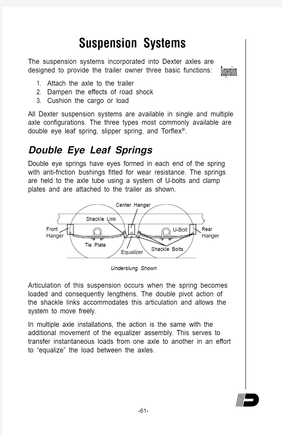
Double eye springs have eyes formed in each end of the spring with anti-friction bushings fitted for wear resistance. The springs are held to the axle tube using a system of U-bolts and clamp plates and are attached to the trailer as shown.Center Hanger
Equalizer Rear Hanger
Front
Hanger
Tie Plate
U-Bolt Shackle Bolts Shackle Link
Underslung Shown
Articulation of this suspension occurs when the spring becomes loaded and consequently lengthens. The double pivot action of the shackle links accommodates this articulation and allows the system to move freely.
In multiple axle installations, the action is the same with the additional movement of the equalizer assembly. This serves to transfer instantaneous loads from one axle to another in an effort to “equalize” the load between the axles.
Grease Lubricated Suspension Bushings Dexter Axle offers an optional heavy duty attaching parts kit for double eye leaf spring suspensions up to 8,000 lb. axle capacity. The kit contains extra heavy shackle links, bronze bushings for the spring eyes and suspension bolts and equalizers equipped with grease fittings to provide a convenient means to lubricate all the pivot points. For availability, contact your nearest Dexter Axle facility or visit us online at https://www.360docs.net/doc/0a12646171.html, for a complete listing of genuine repair parts.
Slipper Leaf Springs
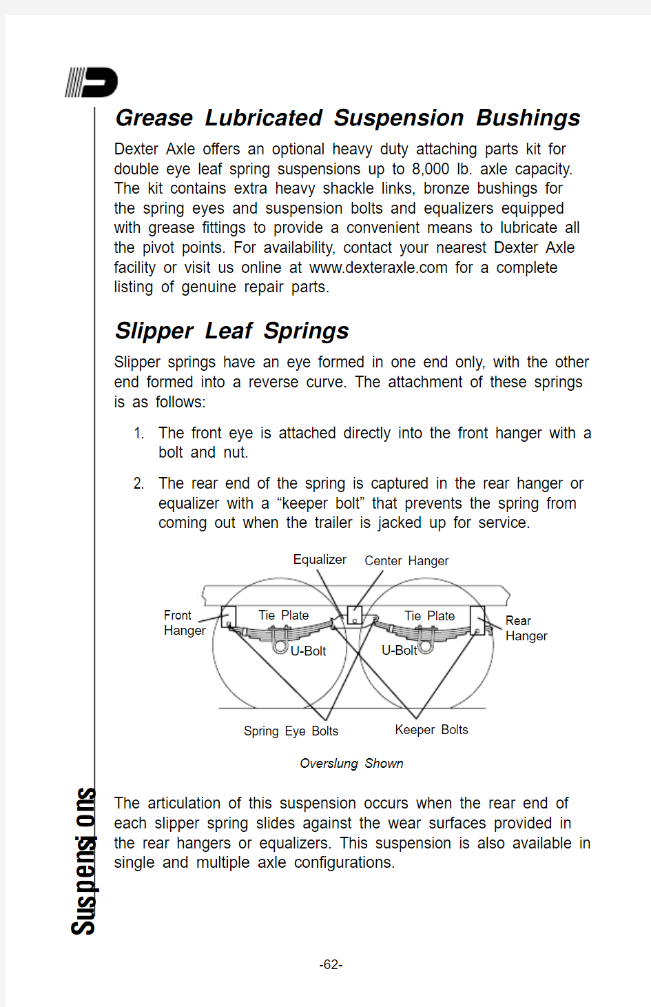
Slipper springs have an eye formed in one end only, with the other end formed into a reverse curve. The attachment of these springs is as follows:
1. The front eye is attached directly into the front hanger with a bolt and nut.
2. The rear end of the spring is captured in the rear hanger or equalizer with a “keeper bolt” that prevents the spring from coming out when the trailer is jacked up for service.
Overslung Shown The articulation of this suspension occurs when the rear end of each slipper spring slides against the wear surfaces provided in the rear hangers or equalizers. This suspension is also available in single and multiple axle configurations.
S u s p e n s i o n s
Suspensions
Inspection and Replacement
All the components of your suspension system should be visually inspected at least every 6,000 miles for signs of excess wear, elongation of bolt holes, and loosening of fasteners. Whenever loose or replaced, the fasteners in your suspension system should be torqued as detailed in the charts below. All wet bolts and equalizers should be greased every 3,000 miles.
Suspension Fastener Torque Values Torque (Ft. Lbs.)
Worn spring eye bushings, sagging springs, or broken springs should be replaced using the following method.
1. Support the trailer with the wheels just off the ground.
2. After the unit is properly supported place a suitable block under the axle tube near the end to be repaired. This block is to support the weight of the axle only, so that suspension COMPONENTS can be removed.
3. Disassemble the U-bolts, nuts, and tie plates.
4. Remove the spring eye bolts and remove the spring and place on a suitable work surface.
5. If the spring eye bushings are to be replaced, drive out the old bushing using a suitable drift punch.
6. Drive the new bushing into the spring eye using a piloted drift punch or a close fitting bolt inserted through the bushing.
7. Reinstall repaired or replaced components in reverse order.
Note: For multiple axle units, the weight of each axle must be supported as outlined in Step 2 before disassembly of any component of the suspension system.If the equalizer or equalizer bushings must be replaced, follow the instructions above for lifting and supporting the trailer unit and then proceed as follows:
S u s p e n s i o n s
1. With both axles blocked up, remove the spring eye bolt, shackle bolt, and equalizer bolt from the equalizer to be repaired or replaced.
2. Take the equalizer to suitable work surface and remove the worn bushings using a suitable drift punch.
3. Drive the new bushings into place using a piloted drift punch or a close fitting bolt through the bushing.
4.
Reassemble in reverse order.All of the pivot points on your standard suspension system have been fitted with anti-friction bearing materials which do not require routine lubrication. When otherwise servicing the unit, these pivot points may be lubricated if you so desire. If your trailer has been fitted with the Heavy Duty Attaching Parts Kit, you should lubricate periodically to ensure long component life.
Torflex ? Suspension
The T orflex ? suspension system is a torsion arm type suspension which is completely self contained within the axle tube. It attaches directly to the trailer frame
using brackets which are an integral part of
the axle assembly. The
T orflex ? axle provides
improved suspension
characteristics relative to
leaf spring axles through
the unique arrangement of a steel torsion bar surrounded by four natural
rubber cords encased in
the main structural member of the axle beam.
Suspensions
The wheel/hub spindle is attached to a lever, called the torsion arm, which is fastened to the rubber encased bar. As load is applied, the bar rotates causing a rolling/compressive resistance in the rubber cords. This action provides the same functions as conventional sprung axles with several operating advantages including independent suspension.
Except for periodic inspection of the fasteners used to attach the T orflex ? axle to the vehicle frame, no other suspension maintenance is required on T orflex ? axles. They are, of course, subject to the maintenance and inspection procedures regarding brakes, hubs, bearings, seals, wheels, and tires as outlined in this manual.
Airflex ? Suspension
The Dexter Airflex ? suspension is a unique combination of Torflex ? axle and conventional air suspension technology. This low maintenance suspension system carries the load on a cushion of air, usually supplied by an on-board compressor and storage tank.
A load leveling valve maintains a constant ride height, regardless of load. As load is added to the trailer, the valve will automatically signal the compressor to supply more air. As loads are removed, the same valve will exhaust air to maintain the same height and ride characteristics.
The Airflex ? suspension air generation kit has a built in dump valve which allows the trailer to be lowered several inches to facilitate loading or leveling. Once loaded, the valve is reversed and the system is pressurized to raise the trailer back up to normal running height.
Axle Adjustment
1. Support the trailer frame on a level surface. If the wheels are already mounted, make sure they are clear of the ground. If the air actuation system has been installed, make sure the air pressure in the air bags is bled off before lifting the trailer.
S u s p e n s i o n s
Suspensions
Note: Lifting the trailer with air system pressurized will
overextend the air bags and can result in damage to the air
bags.2. Measure from king pin to spindle center on each side. T o simplify this process, plumb lines may be dropped from the king pin and from the center line of each spindle end. Measurements “A” and “B” can then be taped on the floor to eliminate any miss measurement due to sagging of the tape for long measurements. Compare A and B measurements (see Figure 1).
3. Suspension front pivot connection is torqued to 270 Ft. Lbs. when the suspension is shipped. The axle should be aligned on the trailer in this condition.
After attachment to the trailer, the axle may be realigned by backing off the 3??" pivot bolt, moving the axle and then torque the pivot bolt to 270 Ft. Lbs. All movement is forward.
4. Re-measure A and B, as before, to assure that “A” and “B” dimensions are within 1???" of each other. If dimensions are
not to specification, then repeat adjustment procedure.
Tandem Axle Adjustment
1. Adjust the second axle using its pivot bolt adjustment to assure distances “C” and “D” are within tolerance.
2. Measure the distances “C” and “D” between the front and rear tandem axles. These distances must be within 1??" of each other.
3. After alignment is completed make sure the pivot bolt is torqued to 270 Ft. Lbs.
4. The limits of 1???" and 1??" appear very small in comparison to the overall dimensions of the vehicle but they are recognized as the maximum permissible limit of misalignment. Also,
the relatively small size of those limits makes accurate measurements important.S u s p e n s i o n s