MAX5498EVKIT+;中文规格书,Datasheet资料

General Description
The MAX5498 evaluation kit (EV kit) is an assembled and tested PCB that demonstrates the MAX5498 10-bit (1024-tap), dual, nonvolatile, SPI?-interface, linear-taper digital potentiometer. Windows ?2000/XP- and Windows Vista ?-compatible software provides a handy user interface to exercise the features of the MAX5498.The EV kit can also be used to evaluate the MAX5494,MAX5495, MAX5496, MAX5497, or MAX5499. The MAX5494/MAX5495 provide two programmable volt-age-dividers, the MAX5496/MAX5497 provide two vari-able resistors, and the MAX5498/MAX5499 provide one programmable voltage-divider and one variable resistor.The MAX5494/MAX5496/MAX5498 devices have 10k Ωend-to-end resistance and the MAX5495/MAX5497/MAX5499 devices have 50k Ωend-to-end resistance.To evaluate the MAX5494–MAX5497 or MAX5499,request a free sample (ETE+ suffix) along with the MAX5498 EV kit.
Features
o 2.7V to 5.25V Single-Supply Operation o Power-On Recall of Wiper Position from Nonvolatile Memory
o On-Board USB Interface Circuit o USB Powered
o USB-PC Connection (Cable Included)
o PCB Pads for User-Supplied Microcontroller Interface Signals
o Labeled Test Points for Potentiometer Signals (L, W, and H)
o Proven USB-Compatible PCB Layout o Evaluates MAX5494–MAX5499
o Windows 2000/XP- and Windows Vista (32-Bit)-Compatible Software
o Lead(Pb)-Free and RoHS Compliant o Fully Assembled and Tested
Evaluates: MAX5494–MAX5499
MAX5498 Evaluation Kit
________________________________________________________________Maxim Integrated Products 1
19-4161; Rev 1; 12/08
For pricing, delivery, and ordering information, please contact Maxim Direct at 1-888-629-4642,or visit Maxim’s website at https://www.360docs.net/doc/0813491527.html,.
Ordering Information
SPI is a trademark of Motorola, Inc.
Windows and Windows Vista are registered trademarks of Microsoft Corp.
+Denotes lead(Pb)-free and RoHS compliant.
Quick Start
Recommended Equipment
Before beginning, the following equipment is needed:?MAX5498 EV kit (USB cable included)
? A user-supplied Windows 2000/XP- or Windows Vista-compatible PC with a spare USB port ?
Two ohmmeters
Note:In the following sections, software-related items are identified by bolding. Text in bold refers to items directly from the EV kit software. Text in bold and underlined refers to items from the Windows operating system.
E v a l u a t e s : M A X 5494–M A X 5499
MAX5498 Evaluation Kit 2_______________________________________________________________________________________
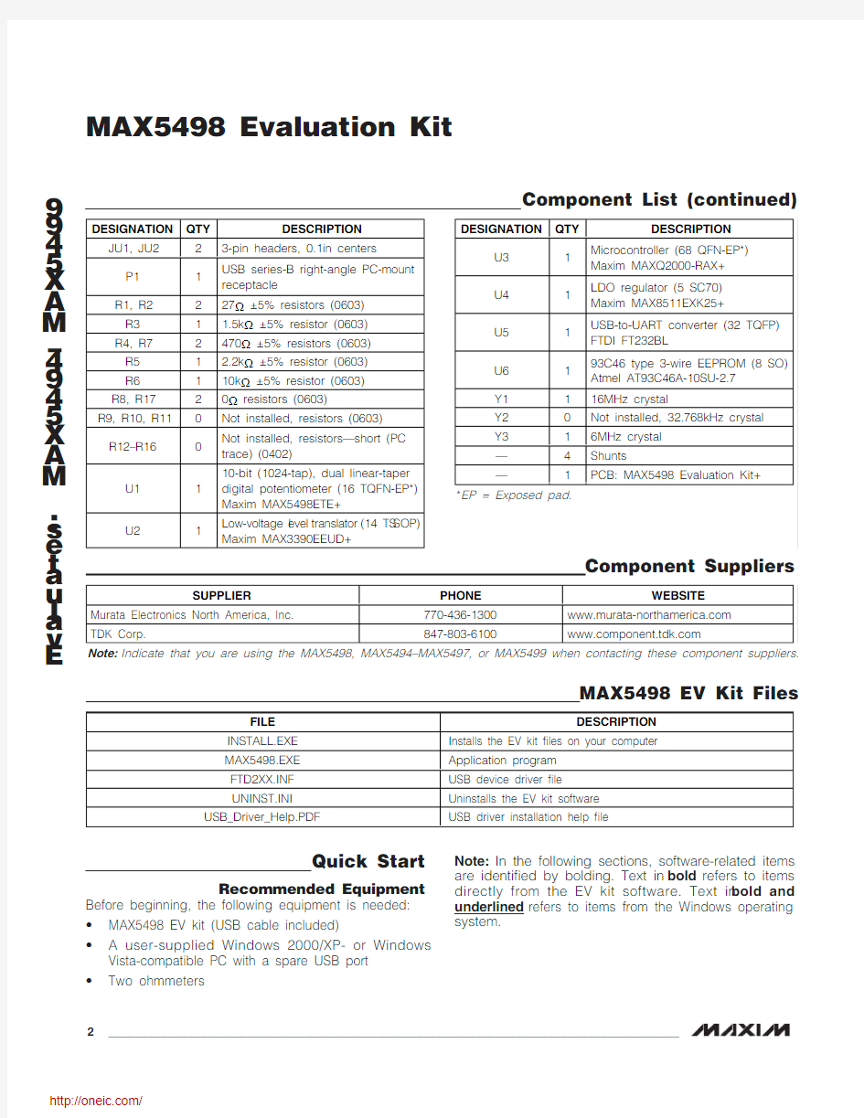
Component List (continued)
Procedure
The MAX5498 EV kit is fully assembled and tested. Follow the steps below to verify board operation. Caution: Do not turn on the power (insert USB cable into computer) until all connections are completed.
1)Visit https://www.360docs.net/doc/0813491527.html,/evkitsoftware to down-
load the latest version of the EV kit software, 5498Rxx.ZIP. Save the EV kit software to a tempo-rary folder and uncompress the ZIP file.
2)Install the EV kit software on your computer by run-
ning the INSTALL.EXE program inside the tempo-rary folder. The program files are copied and icons are created in the Windows Start | Programs menu.
3)Ensure that the MAX5498 EV kit board’s jumper set-
tings are correct (see Table 1 for jumper settings).
4)Connect one of the ohmmeters across the W1 and
L1 pads.
5)Connect the other ohmmeter across the W2 and L2
pads.
6)Connect the USB cable from the PC to the EV kit. A
Building Driver Database window pops up in addi-tion to a New Hardware Found message when installing the USB driver for the first time. If a win-dow that is similar to the one described above is not seen after 30s, remove the USB cable from the board and reconnect it. Administrator privileges are required to install the USB device driver on Windows 2000 and XP. Refer to Application Note 3601:Troubleshooting Windows Plug-and-Play and USB for Maxim Evaluation Kits if any problems arise during this step.
7)Follow the directions of the Add New Hardware
Wizard to install the USB device driver. Choose the Search for the best driver for your device option.
Specify the location of the device driver to be C:\Program Files\MAX5498(default installation direc-tory) using the Browse button. During device driver installation, Windows XP shows a warning message indicating that the device driver Maxim uses does not contain a digital signature. This is not an error condi-tion and it is safe to proceed with the installation.
8)Start the EV kit software by clicking its icon in the
Windows Start menu.
9)The software automatically searches for the
MAX5498. After successful connection, MAX5498 EV Kit connected is displayed in the lower-left cor-ner of the EV kit main window, as shown in Figure 1.
Move the Channel 1or Channel 2track bars and press the Write button to set the wiper position.
Detailed Description of Software The MAX5498 EV kit software graphical user interface (GUI) is a Windows program that provides a convenient means to control the MAX5498 (Figure 1).
Factory Reset Pressing the Factory Reset button returns wipers 1 and 2 (and the nonvolatile memory) to the midscale tap position.
Wipers 1 and 2 Position In the Channel 1group box, set the tap value (either by typing the decimal tap number into one of the edit boxes or by moving the track bar), and then press the Write button.
In the Channel 2group box, set the tap value (either by typing the decimal tap number into one of the edit boxes or by moving the track bar), and then press the Write button.
As confirmation, the Command History window shows the executed SPI sequence. The first hex value is the command byte sent to the device and the next two hex values correspond to the W-L tap value (e.g., SPI: 0x01, 0x80, 0x00).
Nonvolatile Programming In the Channel 1group box, set the tap value (either by typing the decimal tap number into one of the edit boxes or by moving the track bar), and then press the Write NV button.
In the Channel 2group box, set the tap value (either by typing the decimal tap number into one of the edit boxes or by moving the track bar), and then press the Write NV button.
As confirmation, the Command History group box diaplays the executed SPI sequence. The first hex value is the command byte sent to the device and the next two hex values correspond to the W-L tap value (e.g., SPI: 0x11, 0x80, 0x00).
Evaluates: MAX5494–MAX5499MAX5498 Evaluation Kit
_______________________________________________________________________________________3
Volatile/Nonvolatile Data Transfer
In the Channel 1group box, copy the active tap value to nonvolatile memory by pressing the Save active NV button. As confirmation, the Command History group box displays SPI sequence 0x21.
In the Channel 2group box, copy the active tap value to nonvolatile memory by pressing the Save active NV button. As confirmation, the Command History group box displays SPI sequence 0x22.
To copy both of the active tap values to nonvolatile memory, press the Copy Both Wiper Registers to NV Registers button. As confirmation, the Command History group box displays SPI sequence 0x23.
In the Channel 1group box, copy the active tap value to nonvolatile memory by pressing the Load NV active button. As confirmation, the Command History group box displays SPI sequence 0x31.
In the Channel 2group box, copy the active tap value to nonvolatile memory by pressing the Load NV active button. As confirmation, the Command History group box displays SPI sequence 0x32.
To copy both the active tap values to nonvolatile memo-ry, press the Copy Both NV Registers to Wiper Registers button. As confirmation, the Command History group box displays SPI sequence 0x33.
E v a l u a t e s : M A X 5494–M A X 5499
MAX5498 Evaluation Kit 4
_______________________________________________________________________________________
Figure 1. MAX5498 EV Kit Main Window
Command History The Command History group box displays the sequence of bytes sent to the device for each of the GUI’s button controls. For the write controls (Write and Write NV), the group box displays the command byte fol-lowed by the 2 data bytes (wiper setting). The 2 data bytes correspond to the W-L tap value. For the save, load, and copy controls the group box displays the asso-ciated command byte. All values are displayed in hex.
Evaluating Other Devices The MAX5498 EV kit software can also be used to evaluate any of the other devices in the MAX5494–MAX5499 family. The software is reconfigured for each device by choosing the device number from the Options | Device menu bar. To ensure proper opera-tion, install the alternate device on the EV kit before reconfiguring the software.
Keyboard Navigation When you type on the keyboard, the system must know which control should receive the keys. Press the Tab key to move the keyboard’s focus from one control to the next. The focused control is indicated by a dotted outline. Shift + Tab moves the focus to the previously focused control. Buttons respond to the keyboard’s space bar. Some controls respond to the keyboard’s up and down arrow keys. Activate the program’s menu bar by pressing the F10 key, and then press the letter of the menu item you want. Most menu items have one letter underlined, indicating their shortcut key.
Detailed Description of Hardware As configured, the MAX5498 EV kit evaluates the MAX5498 dual, linear-taper potentiometer with one programmable voltage-divider and one variable resis-tor. The potentiometer terminals are accessible from headers H1 and H2. The MAX5498 EV kit hardware and software can also be used to evaluate the MAX5494–MAX5497 or MAX5499. The installed device is con-trolled using a graphical user interface (GUI) that can be downloaded by visiting https://www.360docs.net/doc/0813491527.html,/evkitsoft-ware and clicking on the MAX5498 EVKIT software link.
Ground Referencing Test Equipment The L terminals of each digital pot are linked to ground by placing a shunt on pins 3-4 of headers J1 and J2 (see Table 2). This provides a ground reference when using nonground referenced test equipment (e.g., handheld digital multimeter).
Evaluating the MAX5494–MAX5497 or MAX5499 To evaluate the MAX5494–MAX5497 or MAX5499, con-tact the factory for a free sample of the MAX5494ETE+, MAX5495ETE+, MAX5496ETE+, MAX5497ETE+, or MAX5499ETE+. Refer to the MAX5494–MAX5499 IC data sheet for additional device information.
External User-Supplied SPI Interface The MAX5498 EV kit can be modified for use with an external user-supplied SPI interface. First, with power off and USB disconnected, turn the board over and cut the four traces that are on the back of the board, under-neath location J3. Install a standard dual-row header and connect an external SPI interface. See Figure 2a for the J3 schematic and Figure 4 for J3 trace locations on the bottom side of the PCB.
Single-Supply Operation (VDD) The MAX5498 EV kit’s default configuration is for single-supply operation. The USB interface and microcontroller are powered from the USB bus voltage (5V). The device under test can be powered from an external power sup-ply (2.7V to 5.25V) connected between VDD and GND (see Table 3). When operating with a single supply, the VSS input should be connected to GND (Table 4).
Evaluates: MAX5494–MAX5499MAX5498 Evaluation Kit
_______________________________________________________________________________________5
E v a l u a t e s : M A X 5494–M A X 5499
MAX5498 Evaluation Kit 6_______________________________________________________________________________________
Dual-Supply Operation (VDD, VSS)
To evaluate the MAX5498 EV kit with dual supplies, dis-connect the USB cable from the EV kit and configure JU1 for external power-supply operation (Table 3) and JU2 for dual-supply operation (Table 4). Connect the positive supply between the VDD and GND pads and the negative supply between the VSS and GND pads.When evaluating the EV kit with dual supplies, ensure that (VDD - VSS) ≤5.25V.
Evaluates: MAX5494–MAX5499
MAX5498 Evaluation Kit
_______________________________________________________________________________________
7
Figure 2a. MAX5498 EV Kit Schematic (Sheet 1 of 3)
E v a l u a t e s : M A X 5494–M A X 5499
MAX5498 Evaluation Kit 8
_______________________________________________________________________________________
Figure 2b. MAX5498 EV Kit Schematic (Sheet 2 of 3)
Evaluates: MAX5494–MAX5499
MAX5498 Evaluation Kit
_______________________________________________________________________________________
9
Figure 2c. MAX5498 EV Kit Schematic (Sheet 3 of 3)
E v a l u a t e s : M A X 5494–M A X 5499
MAX5498 Evaluation Kit 10
______________________________________________________________________________________
Figure 3. MAX5498 EV Kit Component Placement Guide—Component Side
分销商库存信息: MAXIM
MAX5498EVKIT+