Cross-Slot-Coupled Microstrip Antenna and Dielectric Resonator Antenna for Circular Polarization
IEEE TRANSACTIONS ON ANTENNAS AND PROPAGATION,VOL.47,NO.4,APRIL 1999
605
Cross-Slot-Coupled Microstrip Antenna and Dielectric Resonator Antenna for Circular Polarization
Chih-Yu Huang,Member,IEEE,Jian-Yi Wu,and Kin-Lu Wong,Senior Member,IEEE
Abstract—Circular polarization (CP)design of microstrip an-tennas and dielectric resonator (DR)antennas through a cross slot of unequal slot lengths in the ground plane of a microstrip line is demonstrated.The proposed CP design is achieved by choosing a suitable size of the coupling cross slot,which results in the excitation of two near-degenerate orthogonal modes of near-equal amplitudes and 90 phase difference.This CP design can be applied to both con?gurations of microstrip antennas and DR antennas and has the advantages of easy ?ne-tuning and less sensitive to the manufacturing tolerances,as compared to their respective conventional single-feed CP designs.For the proposed design applied to a low-pro?le circular disk DR antenna of very high permittivity studied here,a large CP bandwidth,determined from 3-dB axial ratio,as high as 3.91%is also obtained.Details of the proposed antenna designs are described,and experimental results of the CP performance are presented and discussed.Index Terms—Circular polarization,dielectric resonator an-tenna,microstrip antenna,slot coupling.
I.I NTRODUCTION
E
XCITATION of the microstrip antennas and dielectric resonator (DR)antennas through a coupling slot in the ground plane of a microstrip line offers several advantages.For example,no spurious radiation from the feed network can interfere with the radiation pattern and polarization purity of the antenna,since a ground plane separates the feed network and the radiating elements,and no direct contact to the radi-ating elements for the excitation is required,which eliminates the problem of large self-reactance for a probe feed.Also,the slot-coupling feed can provide more degrees of freedom in the feed design.For these reasons,many antenna designs with the slot-coupling feed mechanism have been reported.For the case of achieving single-feed circular polarization (CP)operation,the method of using an inclined coupling slot at 45
National Sun Yat-Se Publisher Item Id
606IEEE TRANSACTIONS ON ANTENNAS AND PROPAGA TION,VOL.47,NO.4,APRIL
1999
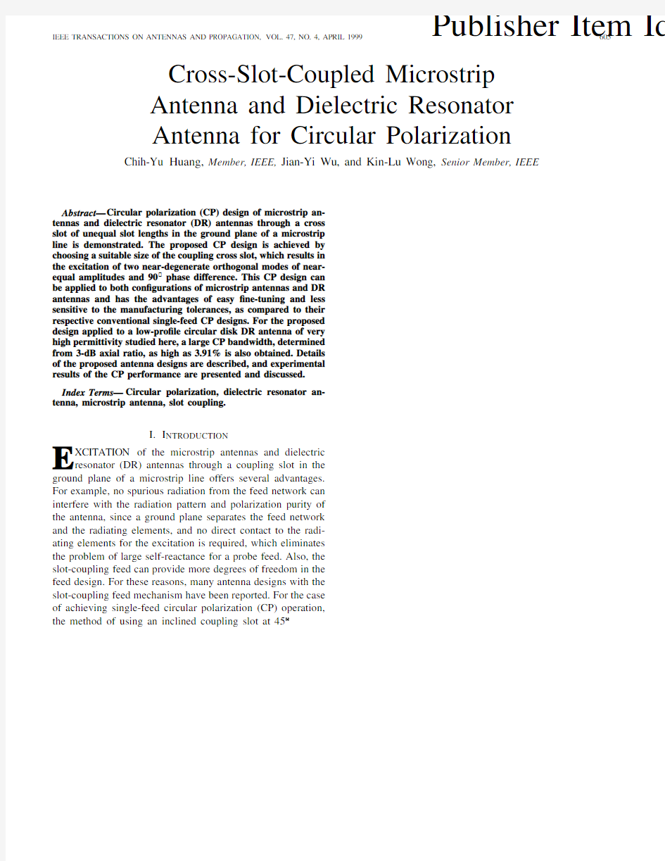
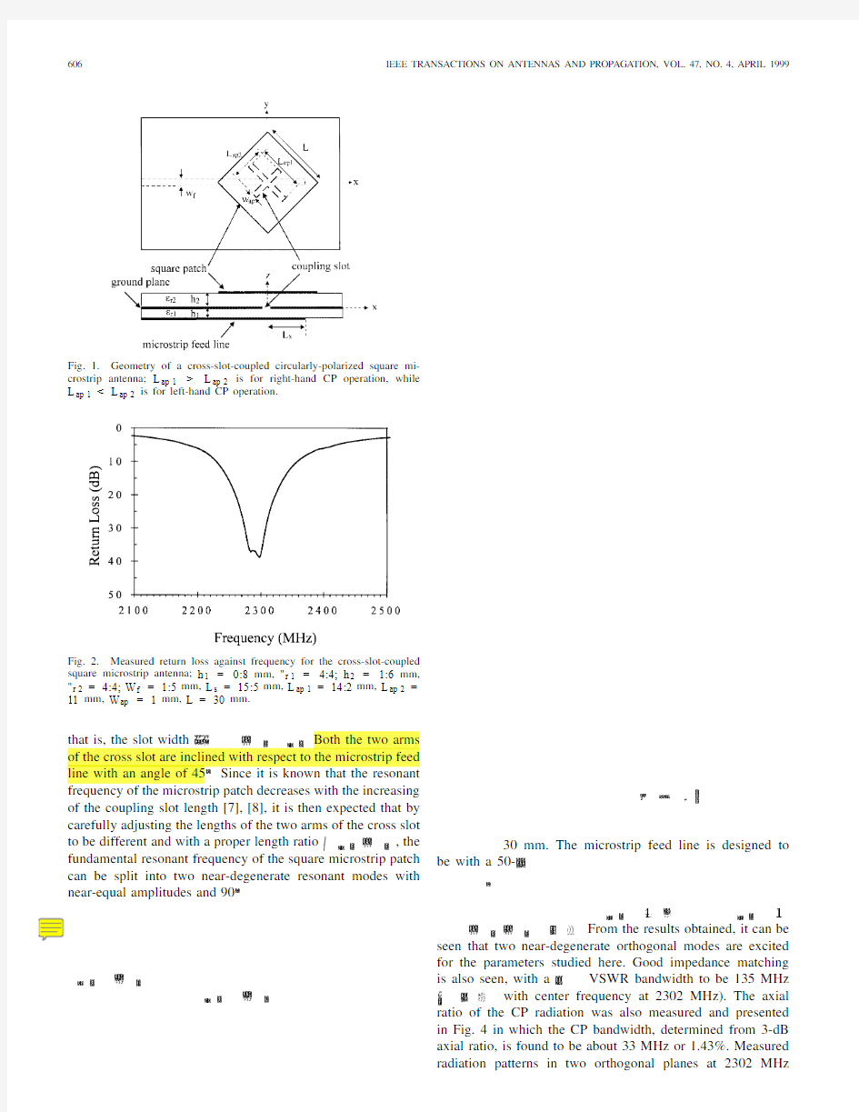
Fig.1.Geometry of a cross-slot-coupled circularly-polarized square mi-crostrip antenna;L ap 1>L ap 2is for right-hand CP operation,while L ap 1 operation. Fig.2.Measured return loss against frequency for the cross-slot-coupled square microstrip antenna;h 1=0:8mm,"r 1=4:4;h 2=1:6mm,"r 2=4:4;W f =1:5mm,L s =15:5mm,L ap 1=14:2mm,L ap 2=11mm,W ap =1mm,L =30mm. that is,the slot width Both the two arms of the cross slot are inclined with respect to the microstrip feed line with an angle of 45Since it is known that the resonant frequency of the microstrip patch decreases with the increasing of the coupling slot length [7],[8],it is then expected that by carefully adjusting the lengths of the two arms of the cross slot to be different and with a proper length ratio ,the fundamental resonant frequency of the square microstrip patch can be split into two near-degenerate resonant modes with near-equal amplitudes and 90 30mm.The microstrip feed line is designed to be with a 50- From the results obtained,it can be seen that two near-degenerate orthogonal modes are excited for the parameters studied here.Good impedance matching is also seen,with a VSWR bandwidth to be 135MHz with center frequency at 2302MHz).The axial ratio of the CP radiation was also measured and presented in Fig.4in which the CP bandwidth,determined from 3-dB axial ratio,is found to be about 33MHz or 1.43%.Measured radiation patterns in two orthogonal planes at 2302MHz HUANG et al.:CROSS-SLOT-COUPLED MICROSTRIP ANTENNA 607 Fig.5.Measured radiation patterns in two orthogonal planes at 2302MHz;antenna parameters are given in Fig. 2. Fig.6.Measured antenna gain in the broadside direction against frequency;antenna parameters are given in Fig.2. are also plotted in Fig.5.Good right-hand CP radiation is obtained.The antenna gain in the broadside direction is about 4dBi and the front-to-back ratio is 16.6dB.The antenna gain in the broadside direction against operating frequency is also plotted in Fig.6.It is seen that,in the 3-dB CP bandwidth,the antenna-gain variation is within 1.5dB.Finally,it should also be noted that,due to the large arm-length ratio (1.29)of the cross slot,the proposed CP design is much less sensitive to the manufacturing tolerances as compared to the conventional single-feed CP designs [9].Also,due to the different arm lengths in the coupling cross-slot,the two near-degenerate modes for CP operation will not be excited with equal amplitudes and thus only near-optimal coupling can be obtained in the present con?guration.And,although only the case with a square microstrip patch is studied here,the present proposed CP design is also expected to be applicable to a circular microstrip patch antenna. III.C ROSS -S LOT -C OUPLED L OW -P ROFILE C IRCULAR D ISK DR A NTENNA FOR CP O PERATION Fig.7shows the con?guration of the proposed CP design for a low-pro?le circular disk DR antenna.It can be seen that this con?guration is similar to that shown in Fig.1,except that the patch substrate and microstrip patch are replaced by a Fig.7.Geometry of a cross-slot-coupled circularly-polarized circular disk DR antenna;L ap 1>L ap 2is for right-hand CP operation,while L ap 1 operation. Fig.8.Measured return loss against frequency for the cross-slot-coupled circular disk DR antenna;h 1=0:8mm,"r 1=4:4;h 2=5:1mm,"r 2=79;W f =1:5mm,L s =10mm,L ap 1=13mm,L ap 2=12mm,W ap =1mm,a =14:72mm. DR of radius a and height The DR studied here is with a very high relative permittivity of By using a high-permittivity DR,low-pro?le DR antenna with relatively low resonant frequencies can be achieved [6].In this study,the DR with a simple shape of circular disk is selected for the analysis.The diameter-to-height ratio of the circular disk DR used here is 5.77 ( mm and VSWR bandwidth of 207 MHz (or about 10.1%with center frequency at 2044MHz)is obtained.In this design,the two arm-lengths of the cross slot are 608IEEE TRANSACTIONS ON ANTENNAS AND PROPAGA TION,VOL.47,NO.4,APRIL 1999 Fig.9.Measured input impedance on a Smith chart for the antenna shown in Fig.8. length ratio of the cross slot is smaller than that of the microstrip-antenna case in Section II,which indicates that the DR antenna is more sensitive to the variation in the arm-length of the coupling cross slot.This cross slot of unequal slot lengths makes the fundamental HEM mode can be roughly estimated from [10] is the speed of light in air. Fig.10shows the measured axial ratio of the CP radiation. A large3-d B CP bandwidth of about80MHz or3.91%is obtained.This large CP bandwidth makes the present design with relaxed manufacturing tolerances.Measured radiation patterns are also plotted in Figs.11and12shows the antenna gain in the broadside direction against operating frequency. Good right-hand CP radiation is obtained,and at resonance, the antenna gain of6.4dBi is observed.The front-to-back ratio is measured to be14.7dB,which suggests that the DR element radiates more effectively than the cross-slot element. The antenna-gain variation in the3-dB CP bandwidth is also seen to be small,within1.0dB.Finally,it can also be expected that the present proposed CP design is applicable for the DR with simple square cross sections.This advantage makes the present design much easier to be implemented,as compared to the conventional designs that requires the use of DR with special con?gurations[2],[3],[5].Also,the present design allows post-adjustments,by?ne-tuning the coupling cross- slot size,to compensate possible manufacturing errors to meet precise frequency speci?cations. Fig.10.Measured axial ratio in the broadside direction against frequency for the antenna shown in Fig. 8. Fig.11.Measured radiation patterns in two orthogonal planes at2044MHz; antenna parameters are given in Fig. 8. Fig.12.Measured antenna gain in the broadside direction against frequency; antenna parameters are given in Fig.8. IV.C ONCLUSIONS By carefully choosing a coupling cross slot of unequal slot lengths,CP operation of the slot-coupled microstrip antennas and DR antennas has been successfully implemented.This CP design method is applicable to the microstrip antennas with square or circular patches and the DR antennas with the DR’s of simple circular or square cross sections.From the results obtained,it is also found that the present proposed HUANG et al.:CROSS-SLOT-COUPLED MICROSTRIP ANTENNA 609 CP design has relatively relaxed manufacturing tolerances,as compared to the conventional CP designs that require slight geometrical modi?cations of the microstrip patch or DR elements.The obtained CP operation also shows good performance,especially for the case with the low-pro?le circular disk DR antenna in which a large CP bandwidth of 3.91%is obtained. R EFERENCES [1]M.I.Aksun,S.L.Chuang,and Y.T.Lo,“On slot-coupled microstrip antennas and their applications to CP operation—Theory and experi-ment,”IEEE Trans.Antennas Propagat.,vol.38,pp.1224–1230,Aug.1990. [2]M. B.Oliver,Y.M.M.Antar,R.K.Mongia,and A.Ittipiboon, “Circularly polarized rectangular dielectric resonator antenna,”Electron.Lett.,vol.31,pp.418–419,Mar.16,1995. [3]K.P.Esselle,“Circularly polarized higher-order rectangular dielectric-resonator antenna,”Electron.Lett.,vol.32,pp.150–151,Feb.1,1996.[4]T.Vlasits,E.Korolkiewicz,A.Sambell,and B.Robinson,“Perfor-mance of a cross-aperture coupled single feed circularly polarized patch antenna,”Electron.Lett.,vol.32,pp.612–613,Mar.28,1996. [5] A.Ittipiboon,D.Roscoe,R.K.Mongia,and M.Cuhaci,“A circularly polarized dielectric guide antenna with a single slot feed,”ANTEM’94Dig.,pp.427–430. [6]K.W.Leung,K.M.Luk,E.K.N.Yung,and https://www.360docs.net/doc/0314684702.html,i,“Characteristics of a low-pro?le circular disk DR antenna with very high permittivity,”Electron.Lett.,vol.31,pp.417–418,Mar.16,1995. [7] C.Y.Huang and K.L.Wong,“Analysis of a slot-coupled cylindrical-rectangular microstrip antenna,”Microwave Opt.Technol.Lett.,vol.8,pp.251–253,Apr.5,1995. [8]P.L.Sullivan and D.H.Schaubert,“Analysis of an aperture coupled microstrip antenna,”IEEE Trans.Antennas Propagat.,vol.34,pp.977–984,Aug.1986. [9] C.Sharma and K.C.Gupta,“Analysis and optimized design of single feed circularly polarized microstrip antennas,”IEEE Trans.Antennas Propagat.,vol.31,pp.949–955,Nov.1983. [10]S.A.Long,M.W.McAllister,and L.C.Shen,“The resonant cylindrical dielectric cavity antenna,”IEEE Trans.Antennas Propagat.,vol.31,pp.406–412,May 1983. Chih-Yu Huang (S’87–M’95)was born in Kaoh-siung,Taiwan,in 1964.He received the B.S.and M.S.degrees in electrical engineering from National Cheng-Kung University from Tainan,Taiwan,in 1986and 1988,respectively,and the Ph.D.degree in electrical engineering from National Sun-Yat-Sen University from Kaohsiung,Taiwan,in 1996. From 1991to 1993,he was employed by the Interpoint Taiwan Corp.,Kaohsiung as an engi-neer involved in thick-?lm hybrid circuits.He is now with the Department of Electrical Engineering, Yung-Ta College of Technology and Commerce,Pingtung,Taiwan,as an Associate Professor.His research interests include antenna theory and design,and dielectric resonator antenna. Jian-Yi Wu was born in Tainan,Taiwan,in 1973.He received the B.S.degree in physics from Chung Yung Christian University,Chung Li,Taiwan,in 1996and the M.S.degree in electrical engineering from National Sun-Yat-Sen University,Kaohsiung,Taiwan,in 1998.Since 1998he has been work-ing toward the Ph.D.degree in the Department of Electrical Engineering at the National Sun-Yat-Sen University. His current research interests are in antenna the-ory and design,microwave engineering,and elec-tromagnetic wave propagation. Kin-Lu Wong (M’91–SM’97)was born in Tainan,Taiwan,in 1959.He received the B.S.degree in electrical engineering from National Taiwan Uni-versity,Taipei,Taiwan,in 1981,and the M.S.and Ph.D.degrees in electrical engineering from Texas Tech University,Lubbock,in 1984and 1986,re-spectively. From 1986to 1987,he was a Visiting Scientist with Max-Planck-Institute for Plasma Physics in Munich,Germany.Since 1987he has been with the Department of Electrical Engineering at National Sun-Yat-Sen University,Kaohsiung,Taiwan,where he became a Professor in 1991.He also served as Chairman of the Electrical Engineering Department from 1994to 1997.He has published more than 130refereed journal papers and 60conference articles and has graduated 16Ph.D.students. Dr.Wong received the Outstanding Research Award from the National Science Council of the Republic of China in 1993.He also received the Young Scienti?c Award from URSI in 1993and the Outstanding Research Award from the National Sun-Yat-Sen University in 1994.He was also listed in Who’s Who of the Republic of China and Who’s Who in the World .He is a member of National Committee of the Republic of China for the International Union of Radio Science (URSI),Microwave Society of the Republic of China,and Electrical Engineering Society of the Republic of China.He was also elected to Board of Directors of the Microwave Society of the Republic of China from 1995to 1997.