Catalytic Wet Oxidation of Phenol with Mn Ce-Based Oxide catalyst
Catalytic Wet Oxidation of Phenol with Mn-Ce-Based Oxide Catalysts:Impact of Reactive Adsorption on TOC Removal
M.Abecassis-Wolfovich,?https://www.360docs.net/doc/0018100154.html,ndau,*,?A.Brenner,?and M.Herskowitz?
Chemical Engineering Department,The Blechner Center for Industrial Catalysis and Process Development,
and Biotechnology and Environmental Engineering,Ben-Gurion University of the Negev,
Beer-Sheva84105,Israel
Catalytic wet oxidation of phenol solutions at low temperatures of80-130°C and space velocities
of1-100h-1using Mn-Ce catalysts was studied with an emphasis on the reactive adsorption
mechanism and total organic carbon(TOC)removal.Eight catalysts(Mn/Ce)6:4)were activated
under different conditions and promoted with alkali metals(K,Cs)or noble metals(Pt,Ru).
The compositions and physical properties of all catalysts were measured.Preliminary runs were
conducted in a batch reactor,but most experiments were carried out in a continuous-flow trickle-
bed reactor.Catalysts containing mixed Mn3O4-CeO2phases pure and promoted with alkali
metals displayed a higher activity and a higher adsorption of organic deposits on their surface.
Noble metals had little effect on process performance.The adsorption capacity of the catalysts
was found to be considerably higher than that reported for activated carbon.Furthermore,
complete regeneration of a catalyst in three consecutive tests was demonstrated under relatively
low temperature and with no loss of activity.The selectivity toward reactive adsorption was
highest on Mn-Ce-Cs catalysts.Low space velocity yielded essentially complete adsorption of
phenol,resulting in deposits on the catalyst surface.The conversion of phenol to water-soluble
oxygenates was found to increase water toxicity.The catalytic reactive adsorption-regeneration
process should become an attractive treatment method for phenol solutions and other complex
waste streams.
Introduction
Catalytic wet oxidation(CWO)with heterogeneous catalysts is a method for the treatment of dilute aqueous waste streams containing a variety of organic pollutants such as phenols.1,2It can be used to mineralize organic contaminants to CO2and H2O or to convert them into nontoxic and biodegradable products.CWO has also become an alternative to the traditional treatment of wastewater with activated carbon,in a periodic adsorp-tion-regeneration process.3,4CWO needs to be con-ducted at relatively low temperature to exclude water evaporation and condensation,short space-time to save reactor volume,and with a high-recovery regeneration procedure to ensure economic feasibility.
Many catalysts have been tested in CWO of phenols: Pt;Pd;Ru/C;5CuO-ZnO/Al2O3;6,7Ru/CeO2;8Pt/CeO2;9 and bulk manganese-cerium oxide composites,pure10-12 or doped with Pt,13Pt-Ag,14or K.15,16Only composites based on manganese-cerium oxides have displayed the ability to remove phenol efficiently at low temperatures of e100°C.At low temperatures,Mn-Ce-based cata-lysts convert phenol to polymeric carbonaceous deposits produced on cerium-related sites that cause substantial catalyst deactivation due to surface blocking.10,12,17The amount of carbon on a spent Mn-Ce catalyst could reach about23wt%.11Introduction of Pt decreases the amount of carbonaceous deposits,13whereas promoting the Mn-Ce catalyst with potassium achieves the op-posite effect.15
Pintar and Levec7measured the formation of poly-meric deposits on the catalyst surface during phenol CWO on CuO-ZnO/Al2O3.They assumed that poly-merization was promoted by the partial oxidation of phenol to aldehydes followed by condensation with phenol.Such polymerization usually occurs on basic catalysts.18It is therefore consistent with promotion of carbon deposition on Mn-Ce composites on cerium-related sites,10,12,17which are more basic than the surface of manganese oxide.19,20The polymeric deposi-tion on the catalyst surface can be considered as the “reactive adsorption”of phenol caused by the catalytic material.Its contribution to TOC removal in phenol CWO reached50-70%.7,13Mn-Ce-based catalysts were tested in phenol CWO at low temperature only in a batch reactor,10,11,13although it was already postulated that the process should be more efficient in a trickle-bed reactor because of the higher solid-to-liquid ratio.7,21 No information has been published on the regeneration of Mn-Ce-based catalysts after deactivation during the CWO of phenol.
The scope of the present study was to demonstrate a controlled reactive adsorption mechanism as a means to improving TOC removal in the CWO of phenol with Mn-Ce-based catalysts in a fixed-bed reactor.Oxidative regeneration procedure to recover the initial catalyst activity was also developed.The information obtained was compared to the conventional adsorptive removal of phenol from wastewater by activated carbon. Experimental Work
Catalyst Preparation.Two samples of manganese and cerium oxide composite(atomic ratio Mn/Ce)6:4) were prepared by coprecipitation from mixed aqueous
*To whom correspondence should be addressed.E-mail: mlandau@bgumail.bgu.ac.il.
?The Blechner Center for Industrial Catalysis and Process Development,Chemical Engineering Department.
?Biotechnology and Environmental Engineering.5089
Ind.Eng.Chem.Res.2004,43,5089-5097
10.1021/ie049756n CCC:$27.50?2004American Chemical Society
Published on Web07/13/2004
solutions of manganese(II)chloride(MnCl2?4H2O,Sigma Chemical Co.)and cerium(III)chloride(CeCl3?7H2O, Sigma Chemical Co.)as described by Imamura et al.22 One hundred milliliters of this solution was poured into 200mL of3M aqueous sodium hydroxide(NaOH,97%, Aldrich Chemicals),and the resulting precipitate was separated by filtration,washed,dried in air at100°C for16h,and then calcined at350°C for3h under a vacuum of85mbar(Mn-Ce-1)or in air(Mn-Ce-2). Addition of potassium or cesium to these Mn-Ce catalysts was done by incipient wetness impregnation that was performed after drying the Mn-Ce precipitate at100°C.The samples were impregnated with aqueous solutions of potassium nitrate(KNO3,Aldrich Chemi-cals)or cesium nitrate(CsNO3,Aldrich Chemicals)to gain4wt%of the alkaline metal.The samples were evacuated at350°C for4h(Mn-Ce-K-1,Mn-Ce-Cs-1)or calcined in air under the same conditions(Mn-Ce-K-2,Mn-Ce-Cs-2).Addition of platinum or ruthe-nium was performed by incipient wetness impregnation
of Mn-Ce catalyst after treatment in a vacuum at350°C for3h with5mg/L aqueous solutions of H2PtCl6or H2RuCl6(Aldrich Chemicals)to gain3wt%of the noble metal.After the samples had been dried at100°C,they were activated in hydrogen for3h at350°C(Mn-Ce-Pt and Mn-Ce-Ru).
Catalyst Characterization.The chemical composi-tions of the catalysts(weight percentage,average of five measurements at different points of the solid)were measured by energy-dispersive X-ray spectroscopy(JEOL JEM5600scanning electron microscope).Surface areas and pore volumes were obtained from N2adsorption-desorption isotherms using the conventional BET and BJH methods.The calcined samples were outgassed under vacuum at250°C.Isotherms were measured at liquid nitrogen temperature with a NOVA-2000(Quan-tachrome,Version7.01)instrument.The phase compo-sitions of the catalysts were tested by X-ray diffraction (XRD).The XRD patterns were collected on a Philips diffractometer PW1050/70(Cu K R radiation)with a graphite monochromator at diffracted beam.Data were recorded at a0.02°step size for2s at each step.The peak positions and the instrumental peak broadening ( )were determined by fitting each diffraction peak by means of APD computer software.The crystal domain size was determined using the Scherrer equation where K)1.000, )0.1°,λ)0.154nm,and B is the peak broadening at2θ)30-45°for different manga-nese oxides and at2θ)48°for cerium oxide.Temper-ature-programmed reduction(TPR)and temperature-programmed oxidation(TPO)experiments were carried out in an AMI-100Catalyst Characterization System (Zeton-Altamira)equipped with a mass spectrometer for outlet component identification(Ametek1000).Catalyst (0.2g)was loaded and treated in10vol%H2-Ar,25 cm3/min(TPR),or5vol%O2-He,25cm3/min(TPO), as the temperature was increased from ambient to420°C at5°C/min.
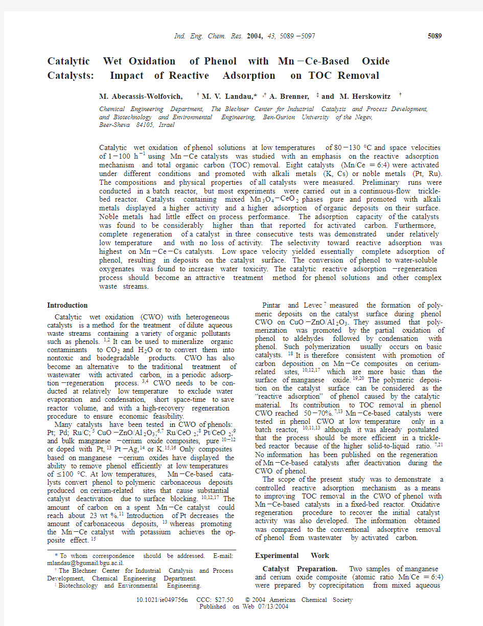
Catalyst Testing Procedures.The wet oxidation of phenol(Sigma Chemical Co.)was carried out in batch and fixed-bed reactors.The preliminarily tests were performed in a stirred autoclave reactor[steady state (SS),300mL,Bu¨chi]at100°C,under a10atm oxygen pressure,with a stirring speed of800rpm,a catalyst loading of2g/L,and a phenol concentration of0.2g/L. Catalyst(0.3g in a powder form to avoid any diffusion limitations)and110mL of distilled water were fed to the reactor,which was pressurized with oxygen to9 atm,and the mixture was then heated under agitation using an oil bath.After the desired reaction temperature had been attained,25mL of concentrated phenol solution(1.2g/L)was loaded into the reactor using an Eldex piston pump.One-milliliter samples were taken periodically for HPLC analysis(GBC,LC1205instru-ment,Zorbax ODS-5C18reverse-phase column,mobile phase acetonitrile/distilled water mixture(8:2vol ratio), 1cm3/min flow rate,UV spectrophotometer for detec-tion,λ)260nm)to determine the phenol concentration. Selected catalysts were tested in a continuous mode using a fixed-bed reactor(SS,20-mm i.d.,24-cm length). CWO was performed at80-130°C with10bar of oxygen pressure and a liquid hourly space velocity (LHSV)of1-100h-1in a fixed-bed reactor rig(Figure 1).The reactor was heated with an electric coil con-trolled by a Eurotherm PID controller.A K-type ther-mocouple was positioned in the center of the catalyst bed.Two independently controlled heating zones kept the axial temperature gradient in the reactor to less than5°C.The oxygen was fed by a Brooks mass controller to a preheater at a rate of25-100mL min-1 (STP conditions)before entering the reactor at the selected temperature.The tested solution containing1 g/L phenol(doubly distilled water)was fed to the reactor by a high-pressure metering pump(SSI HPLC series II isocratic)at20-52mL/h and reaction pressure. Catalyst pellets(0.3-11g,0.4-0.5mm fraction)were diluted with quartz particles of the same size in order to keep a fixed volume of catalyst layer inside the isothermal zone.The liquid effluent was collected in periods of time and analyzed by HPLC to detect the residual phenol concentration.The liquid outlet stream was also analyzed for TOC(total organic carbon)using an Apollo9000HS model TOC combustion analyzer (Tekmar Dohmann)equipped with a nondispersive infrared(NDIR)detector.Testing of phenol oxidation at100°C in a reactor loaded only with glass Raching rings showed that the phenol conversion was below1%. The phenol conversion(X PhOH,%)and TOC conversion
l)
Kλ
[(B2- 2)0.5cos(2θ/2)]
Figure1.Fixed-bed reactor rig for phenol oxidation:1,oxygen
cylinder;2,flowmeter;3,preheater;4,fixed-bed reactor;5,
temperature controller;6,separator and liquid sampling cell;7,
gas sampling;8,nitrogen cylinder;9,liquid pump;10,feed tank.
5090Ind.Eng.Chem.Res.,Vol.43,No.17,
2004
(X TOC,%)were calculated as
and
where C PhOH is the phenol concentration,with the subscripts0and t representing the initial concentration for the batch reactor or the concentration at the inlet for the fixed-bed reactor(C PhOH,0)and the final concen-tration for a batch reactor or the concentration at the outlet for the fixed-bed reactor(C PhOH,t).C TOC is the TOC concentration measured at the fixed-bed reactor inlet or outlet.The reaction rate constants of phenol trans-formation in the batch reactor were calculated assuming first-order kinetics with respect to phenol
To examine the leaching of the metal ingredients,the effluent stream was also analyzed for the presence of Mn and Ce by an inductively coupled plasma(ICP) technique,using an Optima3000Perkin-Elmer ICPOES system.In addition,toxicity bioassays based on the relative inhibition of bioluminescence of marine bacteria were conducted.Toxicity was determined by the Vibrio fischeri bioluminescence assay method,using a model ToxAlert10luminometer(Merck K G a A,Darmstadt, Germany).The Vibrio fischeri bioluminescence assay has been successfully employed for the evaluation of toxicity in complex waste samples and has shown a high sensitivity to the presence of toxicants as well as a good correlation to other toxicity bioassays(Bulich et al.23).
A working solution of luminescent bacteria was pre-pared by reconstituting a vial of freeze-dried Vibrio fischeri cells,purchased from Merck,using1mL of2% (w/v)NaCl.Luminescence of a tested solution and a control having the same amounts of reconstituted bacteria at pH6-8were conducted simultaneously. Toxicity was calculated as the percent decrease in luminescence of the tested solution,compared to the control,and is termed here the percent inhibition. Catalyst Regeneration.The amount of the carbon-aceous material adsorbed on the catalyst surface in continuous runs was calculated according to the time profile of CO2formed during oxidative regenerative treatment.In this treatment the spent catalyst was heated in the reactor under a50mL/min flow rate of oxygen and heating rate of3°C/min up to the required temperature and kept at this temperature until no carbon dioxide was detected at the reactor outlet.A gas sample was taken every few minutes from the exit pipe of the system and analyzed by GC(Gow-Mac580 instrument equipped with a TCD detector and a Pora-pack Q packed column;L)6ft,o.d.)1/8in.,i.d.)3 mm).
Integration of the CO2concentration versus time data using Polymath5.1(Simpson method)yielded the total amount of CO2produced during oxidative regeneration. The corresponding mass of phenol on the surface (m PhOH,s)was calculated from this value and compared with the mass of reacted phenol(m PhOH,r).The ratio between those two values represents here the selectivity
toward reactive adsorption(SRA)and was calculated
as
The catalyst adsorption capacity(CAC)was calculated
as
where m cat is the catalyst mass.When the regeneration
was performed after a small decline in phenol conver-
sion(the start of visible deactivation),the ratio of phenol
amount on the surface to the amount of catalyst was
defined as the steady-state catalyst adsorption capacity
(SS-CAC).When the regeneration was performed after
full deactivation(X PhOH e30%),the ratio was defined as the total catalyst adsorption capacity(total CAC).
SRA and CAC measurements and calculations were
performed three times with an accuracy of5-10%. Results and Discussion
Catalyst Properties.Mn-Ce catalysts containing
different promoters(that affect polymeric deposition)
were tested in a batch reactor.The catalysts tested
included a mixed oxide with optimal CWO Mn/Ce
atomic ratio of6:4established in previous investiga-
tions.12,22This mixed oxide was modified with potas-
sium,cesium,and noble metals(i.e.,platinum or
ruthenium)to examine its ability to accumulate car-
bonaceous deposits during phenol CWO due to different
surface basicity(K,Cs)and oxidation activity(Pt,Ru).
The texture parameters of the different catalysts as well
as their phase compositions are listed in Table1.The
catalysts were treated(1)in air or(2)under vacuum
atmosphere,which caused a change in the structure of
manganese oxide component from Mn5O8to Mn3O4.
XRD diffractograms of samples Mn-Ce-1and Mn-Ce-2
(Figure2)shows sharper peaks for Mn-Ce-1,indicating
a lower dispersion of Mn3O4compared to Mn5O8(crystal
sizes of23-25and9-10nm,respectively)and similar
dispersion of the CeO2phase(4-5nm)(Table1).The
relatively high surface area of the mixed oxides(about
100m2.g-1)is determined mostly by the CeO2phase,
which displayed a much higher dispersion and com-
prised about60%of the catalyst by weight.Taking into
account the theoretical densities of Mn5O8and CeO2of
4.933and7.214g/cm3,respectively,the calculation of
corresponding surface areas according to formula
(where F is the density,d is the crystal diameter)gives 208m2/g for CeO2and122m2/g for Mn5O8.The weight ratio of these phases in the Mn-Ce catalyst treated in air is CeO2/Mn5O8≈1.5,and the measured surface area is128m2/g.This figure compared with the weighted contributions of the calculated surface areas of the oxide components,174m2/g,means that~75%of the oxide crystal surface in the composite is accessible for reacting molecules.Evacuated Mn-Ce-1catalyst had a lower surface area relative to the air-treated Mn-Ce-2be-cause of the lower dispersion of the manganese oxide
X
PhOH (%))(1-C PhOH,t C PhOH,0)×100
X TOC (%))(1-C TOC,outlet
C
TOC,inlet)×100
-ln(1-X PhOH100))kt
SRA)
m
PhOH,s
m
PhOH,r
CAC)
m
PhOH,s
m
cat
SA)
6000
F d
Ind.Eng.Chem.Res.,Vol.43,No.17,20045091
phase (23-25nm,Table 1).It is important to note that the final treatment affected only the manganese oxide phase and not the cerium oxide phase.Modification of Mn -Ce mixed oxide with alkaline and noble metals created substantial changes of its surface area and pore diameter,with no effect on the crystal dimensions of the main phases or appearance of novel phases in the case of alkaline metals (Table 1).Because the amount of inserted modifiers was relatively small (<5wt %),this could indicate a change of the manganese and cerium oxide crystal packing mode during metal addi-tion.
Batch Reactor Experiments.The rate constants and phenol conversions of the different catalysts in batch reactor experiments are presented in Table 2.The manganese oxide component in the form of Mn 3O 4phase yielded a higher catalyst activity relative to that in the form of Mn 5O 8,which was obtained according to a known preparation procedure.22The increase of specific activity by 40%measured for Mn -Ce-1catalyst (vacuum treated)compared with Mn -Ce-2(air treated)corre-
sponds to a decrease of the oxidation state of the Mn ions from 3.2(Mn 5O 8)to 2.6(Mn 3O 4).The same trend was observed for Mn -Ce catalysts modified with alka-line metals.To examine the effect of the different phases on the redox cycle,TPO and TPR experiments were performed (Figure 3a,b).According to the TPO spectra (Figure 3a),treatment in a vacuum shifts the oxygen consumption peak to higher temperature as a result of
Table 1.Textural and Structural Properties of Manganese -Ceria-Based Catalysts
crystal size (nm)catalyst surface area (m 2?g -1)
pore diameter
(nm)
pore volume (cm 3?g -1)
phase composition MnO x CeO 2Mn -Ce-19814.80.36Mn 3O 4,CeO 2254Mn -Ce-212811.50.37Mn 5O 8,CeO 2104Mn -Ce -K-17420.00.37Mn 3O 4,CeO 2244Mn -Ce -K-25422.80.25Mn 5O 8,CeO 210 4.5Mn -Ce -Cs-111114.60.40Mn 3O 4,CeO 223 4.5Mn -Ce -Cs-25319.30.25Mn 5O 8,CeO 210 4.5Mn -Ce -Pt 8314.00.32Mn 5O 8,CeO 225 5.0Mn -Ce -Ru
77
13.3
0.31
Mn 5O 8,CeO 2
24
4.5
Figure 2.X-ray diffractograms of Mn -Ce catalysts:(a)Mn -Ce-1,(b)Mn -Ce-2.
Table 2.Phenol Conversions and Rate Constants
Measured with Mn -Ce-Based Catalysts in Batch Reactor after 60min a
catalyst phenol conversion (%)rate
constant,k
(10-3L ?g -1?min -1)specific rate constant,k ′(10-6L ?m -2?min -1)
Mn -Ce-1808.990Mn -Ce-2707.765Mn -Ce -K-18713.2178Mn -Ce -K-2728.4155Mn -Ce -Cs-19317.8160Mn -Ce -Cs-2607.8147Mn -Ce -Pt 829.0108Mn -Ce -Ru
83
10.2
130
a
[C PhO ]0)0.2g ?L -1,T )100°C,P O 2)10bar,[C cat ])2g ?L -1.
Figure 3.(a)TPO and (b)TPR spectra of Mn -Ce-based catalysts.
5092Ind.Eng.Chem.Res.,Vol.43,No.17,
2004
the lower manganese oxidation state (2.6).In the TPR spectra (Figure 3b),the lack of the low-temperature peak that is assigned to the high-oxidation-state man-ganese species 15corresponded to the formation of the Mn 3O 4phase with a lower oxidation state of Mn ions and a lower dispersion.Most oxygen consumption during O 2treatment and removal during H 2treatment of the evacuated Mn -Ce-1catalyst proceeded at higher temperature (300-350°C)relative to that of air-calcined Mn -Ce-2(150-300°C).This could result in lower efficiency of evacuated Mn -Ce catalyst in phenol con-version to deep oxidation products,facilitating the reactive adsorption of phenol at the catalyst surface.The diminishing redox ability was further observed after addition of alkaline metals.This addition substantially decreased the amount of oxygen adsorbed in TPO experiments by evacuated Mn -Ce catalysts without changing the shape of the TPO (Figure 3a)and TPR (Figure 3b)spectra.
Introduction of K and especially of the more basic Cs strongly increased the rate of phenol conversion (Table 2).Treatment in a vacuum along with the addition of alkaline metals increased the rate of phenol oxidative conversion by a factor of 1.6(K)and 2.2(Cs).Introduc-tion of Pt to the more active evacuated Mn -Ce catalyst had no substantial effect on phenol conversion in agreement with the results of Hamoudi et al.13The same result was measured with Ru promoter.Both noble metals increased the specific rate of phenol conversion (normalized per unit of catalyst surface)by a factor of 1.7-2.
Contribution of Reactive Adsorption to TOC Removal.The evacuated Mn -Ce-based catalysts that displayed higher activities relative to the air-calcined samples were tested in a fixed-bed reactor.The phenol and TOC conversions and product distributions between solid (due to reactive adsorption)and liquid (due to partial oxidation to low-molecular-weight oxygenates)6,7are shown in Table 3.The parameters were measured in a steady-state https://www.360docs.net/doc/0018100154.html,parison of the phenol conversions in Tables 2and 3shows that,in both systems (batch and continuous mode),the same ranking of the samples according to their activities was obtained.In all of the continuous-mode experiments,70-94%of the converted phenol was removed through reactive adsorption and CO 2formation.The carbon mass balance based on the amount of carbon detected in the treated water and on that accumulated on the spent catalyst was 96-100%(Table 3).This indicates that negligible CO 2was formed at the selected testing conditions {T )100°C,WHSV (weight hourly space velocity))0.1g of phenol/[(g of catalyst)?h],LHSV )100h -1},so almost all of the organics removed from the water remained on the catalyst surface,as shown in Table 3.This obser-
vation is different from the results reported by Hussain et al.15for phenol CWO in a batch reactor,where the mineralization selectivity toward CO 2formation reached 33%with Mn -Ce and 95%with K -Mn -Ce catalysts even at lower contact times.This difference in product distributions is a result of the different catalyst activa-tion procedure applied,as,in the present study,an evacuation procedure was used instead of air calcina-tion.This yielded a Mn phase with a lower oxidation state of the metal ions and a lower dispersion.Testing of the Mn -Ce-2catalyst that was calcined in air yielded a lower phenol conversion and a reduction of the deposits on the solids surface.In this case,only 68%of the removed organics remained in the catalyst (Table 3).The remaining 32%was converted to CO 2in agree-ment with the data reported previously.13,15Testing of the evacuated Mn -Ce catalysts showed that the alka-line metals increased the phenol conversion and the contribution of reactive adsorption to phenol conversion (Table 3).It was also found that Pt decreased this contribution (in agreement with the results of Hamoudi et al.13),whereas Ru had no effect.
Figure 4shows phenol conversions obtained with the evacuated Mn -Ce-1catalyst as a function of phenol load for various LHSVs.Two periods can be identified:(i)a steady-state period at a fixed phenol conversion and (ii)a deactivation period displaying a decline of phenol conversions to e 30%.The deactivation is a result of surface blocking with carbonaceous deposits formed in the catalyst pores by copolymerization of phenol with products of its partial oxidation.7Figure 5and Table 4compare the textural properties of fresh and spent Mn -Ce-1catalysts.After deactivation (phenol conversion e 30%),the wide pore size distribution of the fresh Mn -Ce-1catalyst with a maximum in range of 10-20nm was narrowed,and its maximum was shifted to 4nm because of the formation of a thick carbonaceous depos-its layer on the walls of catalyst pores.This is also confirmed by the decreasing values of the surface area,pore diameter,and pore volume (Table 4).
Effects of Additives,LHSV,and Temperature.The steady-state catalyst adsorption capacity (SS-CAC)and the total CAC (measured after X PhOH e 30%)depend on modifiers (K,Cs,Pt,Ru),contact time (LHSV),and temperature,as shown in Tables 5-7.
The effect of the addition of alkaline and noble metals on the catalyst operation time,SRA,SS-CAC,and total CAC is shown in Table 5.Addition of basic additives
Table 3.Phenol and TOC Conversions and Product Distributions Measured with Mn -Ce-Based Catalysts before Visible Deactivation a
conversion (%)
product distribution (%)catalyst phenol TOC liquid solid Mn -Ce-160462377Mn -Ce -K-173621284Mn -Ce -Cs-18275691Mn -Ce -Pt 70493070Mn -Ce -Ru 66522278Mn -Ce-2
52
37
29
50
a
Reaction conditions:[C PhOH ]0)1g ?L -1,T )100°C,P O 2)10bar,LHSV )100h -1.
Figure 4.Phenol conversion as a function of amount of phenol flow through catalyst at different LHSV (T )100°C,P O 2)10bar,[C PhOH ]0)1g ?L -1,Mn -Ce-1catalyst).
Ind.Eng.Chem.Res.,Vol.43,No.17,2004
5093
(K,Cs)reduced both steady-state and deactivation periods,hence reducing catalyst stability.18These find-ings and the steady-state conversions and product distribution presented in Table3indicate that decreased stability is caused by polymer accumulation.The de-crease of the steady-state period and SS-CAC seems to be a result of blocking of the basic sites related to K and especially Cs,being highly reactive in polymeriza-tion reactions.The results for unpromoted Mn-Ce catalyst and that promoted with noble metals,which are shown in Table5,were similar for the steady-state region(duration of operation period and SS-CAC). However,both the deactivation period and the total CAC were smaller with the promoters.This is in agreement with the results of Hamoudi et al.,13who found that Pt-promoted Mn-Ce catalyst is sensitive to deactivation.
The effect of increasing LHSV on phenol and TOC conversions,CAC,and SRA are presented in Table6 for the Mn-Ce-1catalyst.The increase in LHSV had little effect on SS-CAC and total CAC.It substantially affected the period of steady-state operation,phenol conversion,and SRA,as shown in Table6.In addition, as the space time increased,the phenol transformation gradually shifted to reactive adsorption.The increase of space time(lower LHSV)also decreased the specific load(grams of phenol on stream per gram of catalyst) as shown in Figure4,allowing longer operation time and higher phenol conversion.On the basis of the TOC balance,it can be concluded that the higher phenol conversion caused by higher amounts of carbonaceous solids deposited on the catalyst surface(Table6)also results in a higher SRA.It is important to mention that the Mn-Ce-1catalyst at100°C removed95-100% phenol from contaminated water at LHSVs of10-1h-1 with SS-CACs of120-130mg of phenol/g of catalyst (Table6).
The effect of temperature on the phenol and TOC conversions and on the CAC and SRA are presented in Table7for the Mn-Ce-1catalyst.Decreasing the reaction temperature from130to80°C for a steady LHSV gradually enhanced the SRA,SS-CAC,and total CAC.The same trend was obtained when the LHSV was decreased for a steady temperature.Although the phenol conversion decreased with temperature,the selectivity toward reactive adsorption(SRA)increased, due to the fact that there is a higher amount of unreacted phenol that is free to be adsorbed on the catalyst surface(which has a high affinity to adsorb carbonaceous deposits).In this process,more polymeric deposits are adsorbed with lower deactivation ability yielding an increase of SS-CAC and total CAC to170 and420mg of phenol/g of catalyst,respectively(Table 7).Decreasing SS-CAC,total CAC,and SRA with increasing temperature,in the absence of CO2emission, corresponded to production of more liquid products and not to oxidation of carbonaceous deposits.
For a deeper understanding of the observed effects of additives,LHSV,and temperature on the performance of the Mn-Ce catalysts and the reactive-adsorption phenomena,it will be helpful to collect direct informa-tion about the nature of carbonaceous deposits as a
Figure5.Pore size distributions of fresh,spent,and regenerated Mn-Ce-1catalyst.
Table4.Textural Properties of Mn-Ce-1Catalyst
sample surface area
(m2?g-1)
pore diameter
(nm)
pore volume
(mL?g-1)
fresh9814.80.36 spent56 3.80.05 regenerated11511.20.30 Table5.Steady-State and Deactivation Periods,Phenol Adsorption Capacities,and Selectivities toward Reactive Adsorption as a Function of Catalyst Composition a
catalyst steady-
state
period
(h)
deacti-
vation
period
(h)
SS-CAC
(mg of
phenol/g of
catalyst)
total CAC
(mg of
phenol/g of
catalyst)
SRA
(mg of
phenol/
g of reacted
phenol)
Mn-Ce-1 2.514.4120300500
Mn-Ce-K-10.610.540310670
Mn-Ce-Cs-10.6550320810
Mn-Ce-Pt 2.56130270550
Mn-Ce-Ru 2.5 4.2150240660
a Reaction conditions:LHSV)100h-1,[C PhO]0)1g L-1,T) 100°C,P O
2
)10bar.
Table6.Phenol Adsorption Capacity and Reactive Adsorption Selectivity of Mn-Ce-1Catalyst as a
Function of Catalyst Composition a
LHSV(h-1):11050100 phenol conversion b(%)100957560 TOC conversion b(%)100886246 SS-CAC(mg of phenol/g of catalyst)120130130120 total CAC(mg of phenol/g of catalyst)300300290300 SRA(mg of phenol/g of reacted phenol)1000690500500 steady-state period(h)7876 2.5 deactivation period(h)340402514.4 product distribution b(%)
liquid071723 solid100938377
a Reaction conditions:[C PhO]0)1g?L-1,T)100°C,P O
2)10
bar.b Before visible deactivation.Table7.Phenol Adsorption Capacity and Reactive Adsorption Selectivity of Mn-Ce-1Catalyst as a
Function of Reaction Temperature a
temperature(°C):
LHSV(h-1):
80
10
100
10
80
100
100
100
130
100 phenol conversion b(%)8995526075 TOC conversion b(%)8488474647 SS-CAC(mg of phenol/g of catalyst)160130170120110 total CAC(mg of phenol/g of catalyst)420300320300280 SRA(mg of phenol/g of reacted phenol)790690530500410 product distribution b(%)
liquid57102337 solid9593907763
a Reaction conditions:[C PhO]0)1g?L-1,P O
2
)10bar.b Before visible deactivation.
5094Ind.Eng.Chem.Res.,Vol.43,No.17,
2004
function of those parameters,as well as of oxygen pressure.This investigation is now in progress.
A comparison with data on activated carbon3,4,24 shows the advantage of using Mn-Ce catalysts for phenol treatment by CWO.CWO could remove95-100%of the phenol at100°C and LHSV1-10h-1 (Tables6and7),which corresponds to a treatment
capacity up to12L?(kg of catalyst)-1?h-1.This is higher than the typical treatment capacity with activated carbon reported to be4.6-5.5L?(kg of carbon)-1?h-1at the same degree of organics removal.4In addition,the SS-CAC obtained was120-170mg of phenol/g of catalyst,compared with the50-100mg/g capacity of activated carbons.24,25There is,therefore,a great po-tential for further improvement of SS-CAC and treat-ment capacity of Mn-Ce-based mixed oxide catalysts by increasing their surface area,which was relatively low in the samples used because of the low dispersion of the manganese oxide phase.This should yield an economical alternative to the conventional carbon ad-sorption process,compensating for the need to work at elevated temperature and pressure that should be optimized.
Oxidative Regeneration of Mn-Ce-Based Cata-lysts.The concentration profiles of CO2evolved during the oxidative treatment of spent Mn-Ce-1and Mn-Ce-Pt catalysts in oxygen flow are shown in Figure6. The burning off of coke deposits from Mn-Ce-1catalyst starts at~100°C,but the burning rate was relatively low.Increasing the temperature to270°C yielded the highest rate of carbon removal,so that the regeneration process was completed in5h.In the presence of platinum,which is known as an efficient combustion catalyst,the regeneration was completed in about the same period of time but at a much lower temperature (180°C).As shown in Figure6,this regeneration included a short-term temperature jump to~210°C, caused by fast heat evolution that could not be compen-sated by heat exchange.The regeneration treatment fully restored the catalyst textural parameters by complete removal of the coke deposits,as shown for Mn-Ce-1material in Figure5and Table4.The burning of the carbonaceous deposits at less than300°C had no effect on the catalyst structure or the dispersion of the metal oxide phases(XRD).It yielded a complete recovery of the catalyst performance in consecutive CWO-regeneration cycles,as demonstrated for the Mn-Ce-1catalyst in Figure7.The SS-CAC and steady-state operation period for CWO with fresh and regener-ated catalyst in three consecutive runs conducted at100°C and an LHSV of100h-1were in the range of118-122mg of phenol/g of catalyst and2.4-2.6h,respec-tively.This indicates strongly a full recovery of the catalysts.In activated carbon regeneration treatments, the spent activated carbon is regenerated at elevated temperatures(700-1000°C)in steam flow,3,4which leads to degradation of the carbon structure and loss of adsorption capacity.The regeneration temperature of activated carbon could be decreased to240-300°C24by its promotion with transition metal oxides as oxidation catalyst.However,the insertion of such metal oxides decreases the breakthrough adsorption capacity.The breakthrough capacities for the promoted carbon mea-sured in ref24were88-56and62-45mg of phenol/g of carbon,respectively,for the fresh and regenerated carbon.
Leaching of Catalysts and Toxicity Impact.Sev-eral samples of the outlet stream were analyzed for the presence of metal ions that could leach during the process.The extent of leaching was found to be insig-nificant(Mn,0.1mg/L;Ce,0.26mg/L),summing up to less than0.2%of the catalyst amount.Because several experiments resulted in partial conversion of phenol and TOC,the toxicity of the intermediates was also ana-lyzed.This was done for water collected after oxidative treatment with Mn-Ce-1catalyst at100%and60% phenol conversions and for the inlet stream(1000mg/L phenol).The results are presented in Table8,where the toxicity is expressed as percent inhibition of biolumi-nescence.The toxicity of the inlet stream is in agree-ment with reported values for phenol solutions.26The outlet samples for the different conversions show that, at a phenol conversion of60%,the TOC conversion was only46%,which is evident for formation of water-soluble oxygenates as a result of partial phenol oxidation(as no CO2was detected).This might result in intermedi-ates that are more toxic than the parent compounds.27 The outlet stream with the full phenol conversion showed a decrease in the inhibition percentage,which is in agreement with the full TOC conversion.However, the outlet stream with60%phenol conversion showed
Figure6.CO2concentration profiles and temperature variations
during oxidative regeneration of spent Mn-Ce-1and Mn-Ce-Pt catalysts.Figure7.Performance of Mn-Ce-1catalyst after oxidative regeneration cycles.
Table8.Toxicities of the Inlet and Outlet Streams
conversion(%)
sample phenol TOC
inhibition
(%) inlet0041
outlet11001006
outlet2604689 Ind.Eng.Chem.Res.,Vol.43,No.17,2004
5095
a high inhibition,indicating an increase of water toxicity caused by the partial phenol conversion to water-soluble oxygenates.This phenomenon was also observed by Santos et al.,28who found that the products of phenol transformation (hydroquinone and p -benzoquinine)caused an increase in toxicity and also had a synergistic toxicity effect.This indicates that catalytic reactive adsorption -regeneration or complete combustion might be the preferred conversion routes in Mn -Ce-based CWO treatment of phenol solutions.Conclusions
Catalytic wet oxidation of phenol solutions using Mn -Ce-based catalysts can result in three different routes:partial oxidation to soluble oxygenates,deposition (reac-tive adsorption)on the catalyst surface,and full com-bustion to CO 2.Partial conversion of phenol to water-soluble oxygenates is undesirable because it might increase water toxicity and thus limit further applica-tion of a biological process.Evacuation of freshly preci-pitated Mn -Ce composite at 350°C reduces its redox ability.This suppresses the partial oxidation of phenol,makes the contribution of the full combustion route insignificant,and substantially increases the efficiency of reactive adsorption.At space velocities lower than 10h -1at a temperature of 100°C,complete adsorption of phenol was achieved as a result of deposition on the catalyst surface.The reactive adsorption capacity was found to be substantially higher than that reported for conventional activated carbon treatments.Low-temper-ature oxidative regeneration of Mn -Ce-based catalysts showed full recovery of its activity and adsorption capacity in consecutive runs,superior to activated carbon regeneration,which is usually conducted at higher temperatures and result in partial loss of ad-sorption ability.Because of its advantageous adsorption characteristics,low temperature,and efficient regenera-tion,a controlled reactive adsorption -regeneration process using improved Mn -Ce-based catalysts could become an economical and efficient alternative to con-ventional carbon adsorption for the treatment of phenol solutions and other waste streams.Acknowledgment
The authors gratefully acknowledge Dr.A.I.Eren-burg for conducting the XRD measurements.Notation
C )concentration,g ?(L of solution)-1d )crystal diameter,nm
k )reaction rate constant,L ?g -1?min -1
k ′)specific reaction rate constant,L ?m -2?min -1LHSV )liquid hourly space velocity,h -1m )mass,g or mg
P O 2)oxygen pressure,bar
SRA )selectivity to reactive adsorption of phenol,mg of adsorbed phenol/g of reacted phenol
SS-CAC )catalyst capacity to reactive adsorption during steady-state period,mg of adsorbed phenol/g of catalyst T )reaction temperature,°C
total CAC )total catalyst capacity to reactive adsorption,mg of adsorbed phenol/g of catalyst t )reaction time,min
WHSV )weight hourly space velocity,g of phenol ?(g of catalyst)-1?h -1X )conversion (%)
F )crystal density,g/cm 3Sub-and Superscripts
0)initial time at t )0or inlet cat )catalyst PhOH )phenol r )reacted
s )on the surface t )reaction time
TOC )total organic carbon
Literature Cited
(1)Matatov-Meytal,Y.I.;Sheintuch,M.Catalytic Abatement of Water Pollutants.Ind.Eng.Chem.Res.1998,37,309.
(2)Pintar,A.Catalytic Processes for the Purificution of Drink-ing Water and Industrial Effluents.Catal.Today 2003,77,451.
(3)Sonyheimer,J.;Crittenden,J.C.;Summers,R.S.Activated Carbon for Water Treatment ;DVGV -Forschungsstelle:Karlsruhe,Germany,1988.
(4)Wastewater Technology Fact Sheet.Granular Activated Carbon Adsorption and Regeneration ;Report EPA 832-F-00-017;U.S.Environmental Protection Agency,https://www.360docs.net/doc/0018100154.html,ernment Printing Office:Washington,DC,2000.(5)Trawczyn ?ski,J.Noble metals supported on carbon black composites as catalysts for the wet-air oxidation of phenol.Carbon 2003,41,1515.
(6)Pintar,A.;Levec,J.Catalytic Liquid-Phase Oxidation of Refractory Organics in Waste Water.Chem.Eng.Sci.1992,47,2395.
(7)Pintar,A.;Levec,J.Catalytic Oxidation of Organics in Aqueous Solutions:Kinetics of Phenol Oxidation.J.Catal.1992,135,345.
(8)Imamura,S.;Fukuda,I.;Ishida,S.Wet Oxidation Catalyzed by Ruthenium Supported on Cerium(IV)Oxides.Ind.Eng.Chem.Res.1988,27,718.
(9)Duprez,D.;Delanoe,F.;Barbier,J.,Jr.;Isnard,P.;Blan-chard,G.Catalytic Oxidation of Organic Compounds in Aqueous Media.Catal.Today 1996,29,317.
(10)Hamoudi,S.;Larachi,F.;Sayari,A.Wet Oxidation of Phenolic Solutions over Heterogeneous Catalysts:Degradation Profile and Catalyst Behavior.J.Catal.1998,177,247.
(11)Hamoudi,S.;Belkacemi,K.;Larachi,F.Catalytic Oxida-tion of Aqueous Phenolic Solutions Catalyst Deactivation and Kinetics.Chem.Eng.Sci.1999,54,3569.
(12)Chen,H.;Sayari,A.;Adnot,A.;Larachi,https://www.360docs.net/doc/0018100154.html,position -Activity Effects on Mn -Ce -O Composites on Phenol Catalytic Wet Oxidation.Appl.Catal.B 2001,32,195.
(13)Hamoudi,S.;Larachi,F.;Cerrella,G.;Cassanello,M.Wet Oxidation of Phenol Catalyzed by Unpromoted and Platinium Promoted Manganese/Cerium Oxide.Ind.Eng.Chem.Res.1998,37,3561.
(14)Hamoudi,S.;Sayari,A.;Belkacemi,K.;Bonneviot,L.;Larachi,F.Catalytic Wet Oxidation of Phenol over Pt x Ag 1-x MnO 2/CeO 2Catalysts.Catal.Today 2000,62,379.
(15)Hussain,S.;Sayari,A.;Larachi,F.Enhancing the Stability of Mn -Ce -O WETOX Catalysts Using Potassium.Appl.Catal.B 2001,34,1.
(16)Hussain,S.;Sayari,A.;Larachi,F.Novel K-doped Mn -Ce -O Wet Oxidation Catalysts with Enhanced Stability.J.Catal.2001,201,153.
(17)Hamoudi,S.;Larachi,F.;Adnot,A.;Sayari,A.Charac-terization of Spent MnO 2/CeO 2Wet Oxidation Catalyst by TPO-MS,XPS,and S -SIMS.1999,185,333.
(18)Knop,A.;Pilato,L.A.Phenolic Resins ;Springer-Verlag:Berlin,1985.
(19)Tanabe,K.;Misono,M.;Ono,H.;Hattori,Y.New Solid Acids and Bases.Their Catalytic Properties ;Delmon,B.,Yates,J.T.,Eds.;Studies in Surface Science and Catalysis;Elsevier:Amsterdam,1989;Vol.51.
(20)Sugunan,S.;Jalaja,J.M.Electron Donating and Acid -Base Properties of Cerium Oxide and Its Mixed Oxides with Alumina.Collect.Czech.Chem.1994,59,2604.
(21)Iliutaa,I.;Larachi,F.Wet Air Oxidation Solid Catalysis Analysis of Fixed and Sparged Three-Phase Reactors.Chem.Eng.Process.2001,40,175.
5096Ind.Eng.Chem.Res.,Vol.43,No.17,2004
(22)Imamura,S.;Doi,A.;Ishida,S.Wet Oxidation of Ammonia Catalyzed by Cerium-Based Composite Oxides.Ind.Eng.Chem. Prod.Res.Dev.1985,24,75.
(23)Bulich,A.A.;Greene,M.W.;Isenberg,D.L.Reliability of the Bacterial Luminescence Assay for Determination of the Toxicity of Pure Compounds and Complex Effluents.In Aquatic Toxicity and Hazard Assessment;Branson,D.R.,Dickson,K.L., Eds.;American Society for Testing and Materials:Philadelphia, PA,1981;pp338-347.
(24)Matatov-Meytal,Y.I.;Sheintuch,M.Abatement of Pol-lutants by Adsorption and Oxidative Catalytic Regeneration.Ind. Eng.Chem.Res.1997,36,4374.
(25)Ania,C.O.;Parra,J.B.;Pis,J.J.Effect of Texture and Surface Chemistry on Adsorptive Capacities of Activated Carbons for Phenolic Compounds Removal.Fuel Process.Technol.2002, 77-78,337.
(26)Kahru,A.;Maloverjan,A.;Sillak,H.;Pollumaa,L.The Toxicity and Fate of Phenolic Pollutants in the Contaminated Soils Associated with the Oil-Shale Industry.Environ.Sci.Pollut.Res. 2002,1,27.
(27)Brenner,A.New Concept in Industrial Wastewater Man-agement.Environ.Eng.Policy1999,1,217.
(28)Santos,A.;Yustus P.;Quintanilla A.;Garcia-Ochoa F.; Casas J.A.;Rodriguez J.J.Evaluation of Toxicity upon Wet Oxidation of Phenol.Environ.Sci.Technol.2004,38,133.
Received for review March28,2004
Revised manuscript received May17,2004
Accepted June3,2004
IE049756N Ind.Eng.Chem.Res.,Vol.43,No.17,20045097
热轧工艺流程电子教案
热轧工艺流程 热轧工艺流程----初学必看 1.主轧线工艺流程简述 板坯由炼钢连铸车间的连铸机出坯辊道直接送到热轧车间板坯库,直接热装的钢坯送至加热炉的装炉辊道装炉加热,不能直接热装的钢坯由吊车吊入保温坑,保温后由吊车吊运至上料台架,然后经加热炉装炉辊道装炉加热,并留有直接轧制的可能。 连铸板坯由连铸车间通过板坯上料辊道或板坯卸料辊道运入板坯库,当板坯到达入口点前,有关该板坯的技术数据已由连铸车间的计算机系统送到了热轧厂的计算机系统,并在监视器上显示板坯有关数据,以便工作人员进行无缺陷合格板坯的核对和接收。另外,通过过跨台车运来的人工检查清理后的板坯也需核对和验收,并输入计算机。进入板坯库的板坯,由板坯库计算机管理系统根据轧制计划确定其流向。 常规板坯装炉轧制:板坯进入板坯库后,按照板坯库控制系统的统一指令,由板坯夹钳吊车将板坯堆放到板坯库中指定的垛位。轧制时,根据轧制计划,由板坯夹钳吊车逐块将板坯从垛位上吊出,吊到板坯上料台架上上料,板坯经称量辊道称重、核对,然后送往加热炉装炉辊道,板坯经测长、定位后,由装钢机装入加热炉进行加热。 碳钢保温坑热装轧制:板坯进入板坯库后,按照板坯库控制系统的统一指令,由板坯夹钳吊车将板坯堆放到保温坑中指定的垛位。轧制时,根据轧制计划,由板坯夹钳吊车逐块将板坯从保温坑取出,吊到板坯上料台架上上料,板坯经称量辊道称重、核对,然后送往加热炉装炉辊道,板坯经测长、定位后,由装钢机装入加热炉进行加热。 直接热装轧制:当连铸和热轧的生产计划相匹配时,合格的高温连铸板坯通过加热炉上料辊道运到称量辊道,经称重、核对,进入加热炉的装炉辊道,板坯在指定的加热炉前测长、定位后,由装钢机装入加热炉进行加热。其中一部分通过卸料辊道运输的直接热装板坯需通过吊车吊运一次放到上料辊道后直接送至加热炉区。如果炼钢厂可以实现直接热装板坯由上料辊道运送,则可减少部分吊车吊运作业。 板坯经加热炉的上料辊道送到加热炉后由托入机装到加热炉内,加热到设定温度后,按轧制节奏要求由出钢机托出,放在加热炉出炉辊道上。 加热好的板坯出炉后通过输送辊道输送,经过高压水除鳞装置除鳞后,将板坯送入定宽压力机根据需要进行侧压定宽。定宽压力机一次最大减宽量为350 mm。然后由辊道运送进入第一架二辊可逆粗轧机轧制及第二架四辊可逆粗轧机进轧制,根据工艺要求将板坯轧制成厚度约为30-60mm的中间坯。在各粗轧机前的立辊轧机可对中间坯的宽度进行控制。
水工艺设备基础
水工艺设备基础 一、填空题(每空1分,共20分) 1、在水处理工艺中,搅拌器的形式多种多样,应根据工艺要求来选用,常用的搅拌器有:浆式搅拌器、推进式搅拌器、涡轮搅拌器等。 2、Ni-Mo合金是耐盐酸腐蚀的优异材料。最有名的哈氏合金(0Cr16Ni57Mo16Fe6W4)能耐室温下所有浓度的盐酸和氢氟酸。 3、热量传递有三种基本方式:热传导、热对流和热辐射。 4、改变介质的腐蚀特性一般有两种途径:一种是去除介质中有害成分;另一种是加缓蚀剂。 5、从使用角度看,法兰连接可分为两大类,即压力容器法兰和管法兰。 6、按换热设备的换热方式可分为直接式、蓄热式和间壁式换热设备 7、水处理工艺中,最常用的三种膜分离设备为电渗析设备、反渗透设备和超滤设备。 8、吸泥机排泥方式有虹吸、泵吸和空气提升。 二、单选题(每题1分,共10分) 1、陶瓷最大的缺点是( A )。 A.脆性 B.易腐蚀 C.韧性差 D.熔点低 2、水处理工艺设备发生的腐蚀多属于( B )。 A.局部腐蚀 B.全面腐蚀 C.应力腐蚀 D.微生物腐蚀 3、渗透压与溶液的,和有关,而与无关。( B ) A.膜、浓度、温度、溶液性质 B.浓度、温度、溶液性质、膜 C.温度、膜、浓度、溶液性质 D.溶液性质、浓度、膜、温度 4、法兰连接的失效主要表现为( A )。 A.发生泄漏 B.出现缝隙 C.螺栓松动 D.以上皆是 5搅拌式设备有多种形式,哪个不是按功能分的( A )。 A.水利搅拌设备 B.混合搅拌设备 C.搅动设备 D.分散搅拌设备 6、传统的容积式换热器的优点不包括( D )。 A.兼具换热、贮热功能 B.阻力损失小 C.结构简单、管理方便 D.节能 7、曝气的主要作用有( D )。 A.充氧 B.搅拌 C.混合 D.以上都是 8、下列气浮分离设备应用做广泛的是( B )。 A.微孔布气气浮设备 B.压力溶气气浮设备 C.电解气浮设备 D.射流气浮设备 9、下列不是排泥设备种类的是( C )。 A.行车式 B.螺旋输送式 C.平板式 D.中心传动式 10、下列设备不属于计量设备的是( D )。 A.转子流量计 B.电磁流量计 C.超声流量计 D.电动流量计 三、多选题(每题2分,共20分) 1、高分子材料主要包括哪几种?( ACD ) A.树脂 B.塑料 C.合成纤维 D 合成橡胶 2、发生应力腐蚀的三个必要条件( BCD )。 A.一定空气湿度 B.敏感的合金 C.特定的介质 D.一定的静应力 3、卧式容器的支座主要有、和三种。( BCD ) A.耳式支座 B.鞍座 C.圈座 D.支承式支座 4、水工艺中常用的机械搅拌设备主要有哪几种?( ABD ) A.溶液搅拌设备 B.混合搅拌设备 C.分散搅拌设备 D.絮凝搅拌设备。 5、水处理中常用的曝气设备有( ABCDE ) A.表面曝气设备 B.鼓风曝气 C.水下曝气 D.纯氧曝气 E.深井曝气 6、换热器的选型需综合考虑的因素有( ABCE )
【精品】热轧工艺流程
热轧工艺流程 热轧工艺流程——--初学必看1.主轧线工艺流程简述板坯由炼钢连铸车间的连铸机出坯辊道直接送到热轧车间板坯库,直接热装的钢坯送至加热炉的装炉辊道装炉加热,不能直接热装的钢坯由吊车吊入保温坑,保温后由吊车吊运至上料台架,然后经加热炉装炉辊道装炉加热,并留有直接轧制的可能。连铸板坯由连铸车间通过板坯上料辊道或板坯卸料辊道运入板坯库,当板坯到达入口点前,有关该板坯的技术数据已由连铸车间的计算机系统送到了热轧厂的计算机系统,并在监视器上显示板坯有关数据,以便工作人员进行无缺陷合格板坯的核对和接收。另外,通过过跨台车运来的人工检查清理后的板坯也需核对和验收,并输入计算机.进入板坯库的板坯,由板坯库计算机管理系统根据轧制计划确定其流向。
常规板坯装炉轧制:板坯进入板坯库后,按照板坯库控制系统的统一指令,由板坯夹钳吊车将板坯堆放到板坯库中指定的垛位。轧制时,根据轧制计划,由板坯夹钳吊车逐块将板坯从垛位上吊出,吊到板坯上料台架上上料,板坯经称量辊道称重、核对,然后送往加热炉装炉辊道,板坯经测长、定位后,由装钢机装入加热炉进行加热。碳钢保温坑热装轧制:板坯进入板坯库后,按照板坯库控制系统的统一指令,由板坯夹钳吊车将板坯堆放到保温坑中指定的垛位。轧制时,根据轧制计划,由板坯夹钳吊车逐块将板坯从保温坑取出,吊到板坯上料台架上上料,板坯经称量辊道称重、核对,然后送往加热炉装炉辊道,板坯经测长、定位后,由装钢机装入加热炉进行加热。直接热装轧制:当连铸和热轧的生产计划相匹配时,合格的高温连铸板坯通过加热炉上料辊道运到称量辊道,经称重、核对,进入加热炉的装炉辊道,板坯在指定的加热炉前测长、定位后,由装钢机装入加热炉进行加热。其中一部分通过卸料辊道运输的直接热装板坯需通过吊车吊运一次放到上料辊道后直接送至加热炉区。如果炼钢厂可以实现直接热装板坯由上料辊道运送,则可减少部分吊车吊运作业。
南通宝钢热轧产线工艺设备基本情况
南通宝钢热轧产线工艺设备 基本情况 1 总体情况说明 1.1 生产规模 热轧产线为生产规模年产50万t低合金钢棒材,考虑控制冷却技术及小规格切分轧制技术。φ10为三切分工艺,φ12、φ14为两切分工艺,φ16为两切分和单线两种工艺,其余规格为单线轧制工艺。 1.2产品方案 序号品种钢种代表规格年产量比例钢号(mm)(万吨) (%) 1 螺纹钢低合金钢 HRB335、 HRB335E、 HRB400、 HRB400E、 HRB500、 HRB500E φ10~φ14 11.25 22.5 2 φ16~φ18 12 24 3 φ20~φ25 19.5 39 4 φ28~φ36 5 10 5 φ40 2.25 4.5 合计50 100.00 注:连铸坯规格为:150mm×150mm×8000mm,加热炉能力要 求不低于100t/h。
1.3生产工艺流程 1.3.1 车间生产工艺流程框图
连铸 吊运至上料台 辊道输送 推钢入炉 加热 出炉 (不合格坯剔除) 粗轧 切头 中轧 控制冷却 切头 倍尺分段 冷床冷却 冷剪剪切定尺 移送、检查、计数 打捆 称重标志 收集 入库 精轧 1.3.2 生产工艺过程简述
合格的连铸钢坯由炼钢连铸车间用电动平车运输至本车间,然后用吊车吊运至上料台架,坯料由上料台架推入坯料输送辊道,并输送到加热炉入炉端后由推钢机将其从加热炉的端部推到推钢式加热炉中加热。 根据钢种的要求,钢坯在加热炉内加热到1030~1130℃后,按轧制节奏由出钢机从加热炉侧面单根推出炉。如果钢坯有缺陷,由剔除装置从出炉辊道上剔除。 出炉后的热坯,经辊道输送,钢坯开始进入连轧机组轧制。钢坯首先在粗轧机组轧制6个道次,然后轧件由1#飞剪切头后,进入中轧机组轧制,轧成工艺规程要求的断面。 出中轧机组的轧件,再由2#飞剪切去头尾,继续进入精轧机组轧成最终要求的成品断面尺寸。 当轧制过程出现事故时,1#、2#飞剪手动启动,进行连续剪切,将轧件碎断,防止事故进一步扩大。 φ10~φ40mm低合金钢在轧制后立即进入水冷装置进行余热淬火回火处理。 在水冷装置之后设有分段飞剪用来将轧件切成冷床长度(成品倍尺),倍尺飞剪采用优化剪切,随后倍尺轧件沿冷床输入辊道输送,并由升降裙板制动后进入冷床冷却。轧件齐头后由链式移送机按一定间距和数量形成棒材层,然后由托出小车成层移入冷床输出辊道。
水工艺设备基础考试复习要点
水工艺设备基础考试复 习要点 内部编号:(YUUT-TBBY-MMUT-URRUY-UOOY-DBUYI-0128)
《水工艺设备基础》复习要点一考 试类型及题型 1)闭卷; 2)单项选择题;填空题;简答题;计算题;论述题(分值有变化,单选和填空分值有所减少) 二知识点 第一章.水工艺设备常用材料 1)掌握水工艺设备常用材料有哪些 2)了解钢的分类,如按用途分为:结构钢、工具钢和特殊性能钢。 ①按化学成份分类:碳钢和合金钢;A.碳钢按含碳量又可分为:低碳 钢、中碳钢和高碳钢;B.合金钢按含合金元素的含量又可分为:低合金钢、中合金钢和高合金钢;②按照钢中硫和磷的含量又可分为:普通钢、优质钢、高级优质钢;③根据钢的用途又可分为:结构钢、工具钢和特殊性能钢 3)掌握钢的编号的意义:如合金工具钢9SiCr 钢(%);碳素工具钢T8表示什么含义(%) 第二章. 材料设备的腐蚀﹑防护与保温 1. 材料设备的腐蚀与防护 1)了解什么叫腐蚀及其危害 2)掌握设备防蚀技术中关于防蚀结构设计需要遵循的基本原则 3)掌握:a.什么是应力腐蚀及其发生的条件 b.设备防蚀技术中关于改变介质腐蚀特性的途径是什么 4)重点掌握:a.微生物腐蚀产生的原因及其最常见的微生物腐蚀类型;b.水处理工艺设备常用材料的选择原则(可能出简答题) 2. 设备的保温 了解设备保温的目的 第三章水工艺设备理论基础 1. 容器应力理论 1)掌握什么是薄壁容器判断标准 2)了解容器设计的基本要求 1)工艺要求:容器的总体尺寸、接口管的数目与位置、介质的工作压力、填料种类、规格、厚度等一般都要根据工艺生产的要求通过工艺设计计算及生产经验决定。2)机械设计的要求:(1)容器要有足够的强度(2)要有足够的刚度(3)要具有足够的稳定(4)容器必须有足够的严密性(5)抗腐蚀性和抗冲刷性要好(6)在保证工艺要求、和机械设计要求的基础上,应选择较为便宜的材料,以降低制作成本。(7)确保制作、安转、运输及维护方便。 3)重点掌握圆柱壳薄壁容器的应力计算方法(记公式、弄懂每个参数的意义,会用)会出个计算题(课本 P98页) 1
热轧轧制原理及工艺
热轧轧制基本原理及基本工艺 一.概论 铝是目前仅次于钢铁的第二类金属,其板带材具有质轻、比强度高、耐蚀、可焊、易加工、表面美观等特点被广泛的应用于国民经济的各个行业,特别是航空航天、包装印刷、建筑装饰、电子家电、交通运输等领域。比如,航空航天方面,前几天发射的“神八”飞船,上面好多铝及铝合金用品都是西南铝和东轻公司加工制造的,不过这些产品一般都是军工产品,我们目前还没有生产的权利,我们厂也没有参与加工,但是也是铝加工行业的骄傲。 包装印刷方面,大家都熟知的PS版,虽然现在我们已经退出了这个产品的生产竞争行列,但是我们曾经生产过,曾经取得过比较好的生产成绩。建筑装饰方面,我们生产过的主要有铝塑底板带,大批量的各系合金的氧化带等。 电子家电方面较多,前段时间大批量生产的液晶电视背板,键盘料等。交通运输方面,大家熟知的5754声屏障。虽然有些产品我们已经不再生产,但是这些产品我们不再陌生,到超市里面逛街的时候看看电饭煲盖子里的铝板,看看各种大型的液晶电视,可能某些产品所用的铝及铝合金配件就是我们厂生产的呢! 二.热轧的简单概念及特点 热轧是指在金属再结晶温度以上进行的轧制。 再结晶就是当退火温度足够高,时间足够长时,在变形金属或合金的纤维组织中产生无应变的新晶粒(再结晶核心),新晶粒不断的长大,直至原来的变形组织完全消失,金属或合金的性能也发生显著变化,这一过程称为再结晶,其中开始生成新晶粒的温度称为开始再结晶温度,显微组织全部被新晶粒所占据的温度称为终了再结晶温度,一般我们所称的再结晶温度就是开始再结晶温度和终了再结晶温度的算术平均值,一般再结晶温度主要受合金成分、形变程度、原始晶粒度、退火温度等因素的影响 以上就是理论上的热轧的简单原理,在我们铝加工行业的实际生产中主要的体现是,当铸锭在加热炉内加热到一定的温度,也就是再结晶温度以上时,进行的轧制,而这一个温度的确定主要依据是铝合金的相图,也就是最理想化的情况下,加热温度的确定为该合金在多元相图中固相线80%处的温度为依据,这就牵扯到了不同合金多元相图的问题,比较深奥,所以我们只要知道,加热温度的确定是以该合金固相线的80%为依据,在制度的执行中,根据实际的生产情况,根据设备的运行情况,多加修改所得到的适合该合金生产的温度 热轧的特点: 1、能耗低,塑性加工良好,变形抗力低,加工硬化不明显,易进 行轧制,减少了金属变形所需的能耗 2、热轧通常采用大铸锭、大压下量轧制,生产节奏快,产量大, 这样为规模化大生产创造了条件 3、通过热轧将铸态组织转变为加工组织,通过组织的转变使材料 的塑性大幅度的提高 4、轧制方式的特性决定了轧后板材性能存在着各向异性,一是材
水工艺设备基础知识点
1、水工艺设备常用的金属材料主要有碳钢、铸铁、合金钢、不锈钢以及部分有色金属材料等。 2、按照钢中硫和磷的含量可分为普通钢、优质钢和高级优质钢。普通钢 S<=0.055%,P<=0.045%;优质钢S、P均应<=0.040%;高级优质钢S<=0.030%,P<=0.035%。 3、根据钢的用途可分为结构钢、工具钢、特殊性能钢。 4、Q275表示屈服强度为275MPa的碳素结构钢。 5、含碳0.45%(万分之四十五)左右的优质碳素结构钢编号为45钢。 6、碳素工具钢的含碳量一般介于0.65%~1.35%之间。 7、30CrMnSi钢,其平均含碳量为0.3%,铬、锰、硅三种合金元素的含量均小于1.5% 8、金属材料的基本性能是指它的物理性能、机械性能、化学性能、和工艺性能。 9、化学成分的变化对钢材的基本力学性能如强度及塑韧性等有较大的影响。 10、屈服极限是金属材料开始产生屈服现象时的应力,以σs表示,单位为MPa。对于没有明显屈服点的材料,规定以产生0.2%塑性变形时的应力作为屈服强度,表示。 以σ 0.2 11、疲劳强度是指材料在经受N次应力循环而不断裂时的最大应力,以σ-1(纯 (扭转疲劳)表示,单位为MPa。N为102~105次发生破坏的为低弯曲疲劳)τ -1 循环疲劳破坏,多发生在容器构件上,N超过105次的为高循环疲劳破坏,多用于一般机械零件,钢铁材料N为107,有色金属和某些超高强度钢N为108。12、材料在加工方面的物理、化学和机械性能的综合表现构成了材料的工艺性能,又叫加工性能。 13、水工艺设备主要零部件的制造工艺过程主要是焊接、锻造、切削、冲压、弯曲和热处理 14、在铸铁中加入某些合金元素可以大大提高它在一些介质中的耐蚀性。如硅、铬、铝,可使铸铁表面形成连续、致密、牢固的表面膜;镍能获得耐碱性介质腐蚀性能优良的奥氏体铸铁;稀土元素、镁,能使石墨球化,从而大大改善高硅铸铁的力学性能和工艺性能 15、耐蚀低合金钢通常是指在碳钢中加入合金元素的总量低于3%左右的合金。加入少量的铜、铬、铝等元素能使钢表面形成稳定的保护膜,从而提高钢在海水、大气等介质中的耐蚀性。 16、耐蚀低合金钢有:耐大气腐蚀钢种:铜系列有16MnCu、09MnCuPTi、 15MnVCu、10PCuRe等;磷钒系列有10MnPV等,磷稀土系列有08MnPRe、12MnPRe等;磷铌稀土系列有10MnPNbRe等;耐海水腐蚀钢种:10CrMoAl、09CuWSn、08PV、10MnPNbRe等;耐硫化氢腐蚀钢种:12AlV、12MoAlV、15Al3MoWTi、12Cr2MoAlV、40B。 17、不锈钢是铬、镍含量较高的合金钢。 18、不锈钢按显微组织可分为马氏不锈钢、铁素体不锈钢和奥氏体不锈钢。 19、不锈钢按化学成分可分为铬不锈钢和铬镍不锈钢。 20、奥氏体不锈钢可用于制作在腐蚀性介质中使用的设备。 21、工业上钢铁称为黑色金属。除钢铁以外的金属称为有色金属 22、在水处理工程、化工机械与设备制造中应用较多的有色金属,主要有铜、铝、钛、铅、镍及其合金 23、黄铜:铜与锌组成的合金称为黄铜。
1780热轧生产工艺与设备
1780热轧生产工艺与设备 6.1 1780热轧的产品、规格及生产能力 宝钢股份不锈钢分公司1780mm热轧以热轧不锈钢钢卷为主导产品,同时发挥轧机能力大、控制水平高的特点,兼顾生产薄规格、高强度、高附加值的优质碳素结构钢、低合金钢等。不锈钢包括200、300、400系列,其中奥氏体不锈钢约占总量的70%,铁素体不锈钢占25~27%,马氏体不锈钢占3~5%;碳素钢中包括双相、多相微合金钢,高强度钢及特殊用途钢等品种,且碳钢产品中以薄规格为主,厚度1.2~3.5mm约占80%,以生产热轧酸洗、热轧镀锌及以热代冷用钢卷。 一期的设计产量为年产热轧钢卷282.2万吨,其中不锈钢69.8万吨,碳钢212.4万吨。由于二期项目中炼钢扩建了炼钢和连铸生产线,热轧增加了3号加热炉,从而增加了近70万吨的不锈钢生产能力。 成品规格如下表所示:
代表钢种 成品厚度 (mm) 成品宽度(mm) 碳钢 低合金 钢 SPHC,SPHD,SPHE,10P CuRE, SPA-H,SM400A -C SM490A - C,15MnV,09MnNb 1.2~1 2.75 750~1630 不锈钢 304,304L,316,316L, 410,420,409,430 2.0~10.0 750~1600 6.2 1780热轧的生产设备及工艺流程 6.2.1热轧生产线的主要工艺设备: 1 10 3 4 5 6 7 8 9 11 12 3 2 1 2
1-三座加热炉;2-高压水除鳞箱(HSB );3-粗轧除鳞;4-粗轧前大立辊(VE );5-粗轧机(RM );6-热卷箱(CB );7-飞剪(CS );8-精轧前除鳞装置;9-精轧前立辊(F1E );10-7机架的精轧机;11-层流冷却;12-两台地下卷取机(DC )。 6.2.2 生产工艺流程 板坯加热 高压水除鳞 粗轧 飞剪 热卷箱 热卷箱炉 精轧前除鳞 精轧机 层流冷却 卷取 钢卷运输 入库 检查取样 打包、验收 发货 平整分卷 发货、打包、验收
水工艺设备基础课后习题解答-12页精选文档
第1章水工艺设备常用材料 1. 金属材料的基本性能包括哪几个方面的内容?你认为水工艺设备对金属材料的哪些性能要求更高?怎样才能满足这些要求? 答:使用性能:1 化学性能:抗氧化性和耐腐蚀性。2 物理性能:密度,熔点,热膨胀系数,导热性以及弹性模量等。3 机械性能:弹性,塑性,强度和韧性。工艺性能:可焊性,可锻性,切削加工性,成型工艺性,热处理性能。 我觉得水工艺设备对金属材料的强度,刚度和抗腐蚀性的性能要求更高。 按照实际的工程需要,通过不同材料间的比较,从中选出较优的材料。 2.钢的分类与编号如何? 答:分类:按化学成分分类:碳钢和合金钢。分别又分为低中高。 按质量分类:普通钢,优质钢,高级优质钢(硫磷的含量区分) 用途分类:结构钢,工具钢和特殊性能钢。 编号:(1)普通碳素结构钢:Q+数字表示。Q275表示屈服强度为275MPa的碳素结构钢。 (2)优质碳素结构钢:采用两位数字表示钢中平均含碳量为万分之几。含碳为0.45%的编号为45钢。 (3)碳素工具钢:以“T”开头,后面标以数字表示含碳量的千分之几。高级就在最后加以“A”。 (4)合金结构钢:两位数字+元素符号+数字来表示。两位数字表示含碳量的万分之几,元素符号表示所含的合金元素,数字表示该元素的百分之几。 (5)合金工具钢:和合金结构钢类似。含碳量大于或等于1%时不予标出,小于的话用千分之几表示。 3. 影响钢材性能的因素主要有哪些? 答:碳是决定钢材的主要元素,随含碳量增加,钢的强度和硬度将不断提高,而塑性和韧性则会随之下降。硫是一种有害元素,产生“热脆”现象。 磷也是一种有害元素,产生“冷脆”现象。锰是一种有益元素,作为脱氧剂和合金元素,减轻硫的有害作用,提高钢的强度和硬度。硅是一种有益元素,作为脱氧剂和合金元素,提高强度,硬度,弹性,降低塑性和韧性。氧,氮:未除尽的氧氮大部分以化合物形式存在,降低强度,冷弯性能和焊接性能。氧增加热脆,氮增加冷脆。钛,钒,铌:钢的强脱氧剂和合金元素,改善韧性,提高强度。4. 合金钢有哪些类型?何谓耐蚀低合金钢?耐大气腐蚀、海水腐蚀的低合金钢中各含哪些主要合金元素? 答:按合金元素分为低中高合金钢。按用途分为合金结构钢,合金工具钢和特殊性能钢。特殊性能刚又分为不锈钢和耐热钢。 耐蚀低合金钢:在碳钢中加入合金元素的总量低于3%左右的合金,根据合金种类和含量不同起到不同的耐蚀性能。 耐大气腐蚀:铜,铬,铝耐海水腐蚀:铜,铬,铝,镍。 5. 不锈钢有哪些类型?在酸性介质、碱性介质及中性水溶液中是否可以选用同一种不锈钢?简述理由。 答:按显微组织为马氏体不锈钢,铁素体不锈钢和奥氏体不锈钢。按化学成分为铬不锈钢和铬镍不锈钢。不可以,因为不同介质溶液中PH值不同,对不锈钢的化学反应都不一样,所以不能用同一种不锈钢,应该有所针对的选择。 6. 铝、铜及其合金的主要性能特点是什么?主要用于什么场合? 答:铜及其合金具有高的导电性,导热性,塑性和冷韧性,并且在许多介质中具
水工艺设备基础 期末复习
第一章水工艺设备常用材料 1.水工艺设备常用的金属材料主要有:碳钢、铸铁、合金钢、不锈钢及部分有色金属材料等。 2.钢的分类:按化学成分分为碳钢和合金钢,按硫磷含量分为普通钢、优质钢、高级优质钢,按用途分为结构钢、工具钢、特殊性能钢。 3.钢的编号:Q+数字表示屈服强度值;标注A、B、C、D,表示钢材质量等级,A级最低,D级最高;标注F为沸腾钢,未标注为镇静钢:如q235—A·F,表示屈服强度为235MPa的A级沸腾钢。 4.合金结构钢编号:利用“两位数字+元素符号+数字”来表示,两位数字代表钢种平均含碳量的万分之几,元素符号表示钢中所含的合金元素,数字代表该元素的平均含量的百分之几,若平均含量低于1.5%,则不标明含量,若平均含量大于1.5%、2.5%、3.5%……,则相应地以2、3、4……表示。如12CrNi3钢,其平均含碳量为0.12%,平均含铬量小于1.5%,平均含镍量为3%。 5.合金工具钢:当其平均含碳量大于或等于1.00%时,含碳量不予标出,小于1.00%时,以千分之几表示,其余表示方法与合金结构钢相似,如9SiCr,其平均含碳量为0.9%,硅和铬的平均含量均小于1.5%。 6.金属的基本性能是指它的物理性能、机械性能、化学性能和工艺性能。 7.钢中的有益元素包括锰和硅,有害元素包括硫(热脆、断裂韧性降低)和磷(冷脆、但提高在大气中耐蚀性)。 8.材料的机械性能主要指材料的弹性、塑性、强度和韧性(冲击韧性、断裂韧性、无塑性转变温度)。 9.材料的工艺性能主要指材料的可焊性、可锻性、切削加工性、成型工艺性和热处理性能。 10.有色金属:工业上钢铁称为黑色金属,除钢铁以外的金属称为有色金属。 11.铜合金及其编号:铜与锌组成的合金称为黄铜,HSn70—1表示含铜70%,含锡1%的锡黄铜;铜合金中的主加元素不是锌而是锡、铝、硅等其他元素,称为青铜,QSn4—3,表示平均含锡量4%,含锌量3%的锡青铜。 12.无机非金属材料包括天然岩石、铸石、陶瓷、搪瓷、玻璃、水泥等。 13.陶瓷以黏土为主要原料,其刚度、硬度是各类材料中最高的,在室温下几乎没有塑性,具有很好的耐火性能和不可燃烧性,最大的缺点是脆性和热稳定性低,大多数陶瓷是良好的绝热体和绝缘体。 14.陶瓷和搪瓷的区别:搪瓷是金属和瓷釉的复合材料,兼有金属设备的力学性能和瓷釉的耐腐蚀性能。 15.高分子化合物的合成:加聚反应(无副产物)、缩聚反应(析出低分子物质)。 16.高分子材料性能:重量轻、高弹性、滞弹性、塑性和受迫弹性、强度(比金属低)与断裂(脆性断裂、韧性 断裂)、韧性(好)、减摩、耐磨性(好)、绝缘性(好)、耐热性(差)、耐蚀性(只化学腐蚀)、老化。 17.高分子材料主要包括合成树脂、合成橡胶和合成纤维三大类。 18.塑料的组成:塑料是指以有机合成树脂为主要组成材料,与其他配料混合,通过加热、加压塑造成一定形状的产品。塑料的性能主要取决于树脂,但在合成树脂中加入添加剂可对塑料进行改性。组成塑料的物质主要包括:合成树脂、填料(或增强材料)、固化剂、增塑剂、稳定剂、润滑剂、着色剂、阻燃剂。 19.塑料按受热性能分为热塑性塑料(加热时软化,可塑造成型,冷却后变硬,此过程可反复进行),热固性塑料(初加热时软化,可塑造成型,但固化后再加热,将不再软化,也不溶于溶剂)。 20.复合材料:为多相或多组成体系,全部相可分为两类,一类为基本相,主要起胶粘剂作用;另一类为增强相,起提高强度或韧性的作用。 21.复合材料性能特点:比强度和比刚度高、抗疲劳性能好、减振能力强、高温性能好、断裂安全性高。 第二章材料设备的腐蚀、防护与保温 1.腐蚀:是材料与它所处环境介质之间发生作用而引起材料的变质和破坏。 2.金属氧化的条件:金属氧化物的分解压低于0.022MPa,该金属就有可能在空气中氧化。 3.金属氧化膜起保护作用的条件: ①生成的金属膜必须致密、完整,能把金属表面全部遮盖住; ②金属氧化物本身是稳定、难溶和不挥发的,且不易于介质作用而被破坏; ③氧化膜与基体结合良好,有相近的热胀系数,不会自行或受外界作用而剥离脱落; ④氧化膜有足够的强度、塑性,足以经受一定的应力、应变的作用。 4.钢铁的气体腐蚀:钢铁在高温气体环境中很容易受到腐蚀,常见类型有:高温氧化、脱碳、氢蚀和铸铁肿胀;防止措施:合金化、改善介质、应用保护性覆盖层。
最新作业-给排水设备工艺黄廷林-主编-课后答案
精品文档 第一章水工艺设备常用材料 1. 金属材料的基本性能包括哪几个方面的内容?你认为水工艺设备对金属材 料的哪些性能要求更高?怎样才能满足这些要求?答:使用性能:1 化学性能:抗氧化性和耐腐蚀性。2 物理性能:密度,熔点,热膨胀系数,导热性以及弹性模量等。3 机械性能:弹性,塑性,强度和韧性。工艺性能:可焊性,可锻性,切削加工性,成型工艺性,热处理性能。我觉得水工艺设备对金属材料的强度,刚度和抗腐蚀性的性能要求更高。按照实际的工程需要,通过不同材料间的比较,从中选出较优的材料。 2. 影响钢材性能的因素主要有哪些?答:碳是决定钢材的主要元素,随含碳量增加,钢的强度和硬度将不断提高,而塑性和韧性则会随之下降。硫是一种有害元素,产生“热脆”现象。磷也是一种有害元素,产生“冷脆”现象。锰是一种有益元素,作为脱氧剂和合金元素,减轻硫的有害作用,提高钢的强度和硬度。硅是一种有益元素,作为脱氧剂和合金元素,提高强度,硬度,弹性,降低塑性和韧性。氧,氮:未除尽的氧氮大部分以化合物形式存在,降低强度,冷弯性能和焊接性能。氧增加热脆,氮增加冷脆。钛,钒,铌:钢的强脱氧剂和合金元素,改善韧性,提高强度。 3. 不锈钢有哪些类型?在酸性介质、碱性介质及中性水溶液中是否可以选用同一种不锈钢?简述理由。答:按显微组织为马氏体不锈钢,铁素体不锈钢和奥氏体不锈钢。按化学成分为铬不锈钢和铬镍不锈钢。不可以,因为不同介质溶液中PH值不同,对不锈钢的化学反应都不一样,所以不能用同一种不锈钢,应该有 所针对的选择。 4、高分子材料主要有哪些类型?耐蚀有机高分子有哪些类型?各有什么特点?答:按照化学组分分:碳链有机聚合物、杂链有机聚合物、元素有机聚合物、无机聚合物。常用于水工程及水工艺设备中的高分子材料有:塑料、橡胶、纤维和胶粘剂等。耐蚀有机高分子类型有:热塑性树脂、工程塑料类、热固性树脂等。热塑性树脂中聚乙烯、聚丙烯的应用占主流。工程塑料类虽然有优异的耐腐性能,但因其价格的原因, 在中等的腐蚀环境中首选的仍是价廉易得、加工容易的材料。热固性树脂大多制成复合材料使用。 5.复合材料主要有哪些性能特点? 答:比强度和比刚度高,抗疲劳性能好,减振能力强,高温性能好,断裂安全性高。 精品文档. 精品文档第二章、材料设备的腐蚀、防护与保温 答:氢蚀是指在高温高压环境下,1. 什么叫氢蚀?它对钢的性能有什么影响?氢蚀后使钢材力学性氢进入金属内与一种组分或元素产生化学反应使金属破坏。能下降,强度、塑性下降,呈脆断性破坏、氢蚀一旦发生,便无法消除,是不可逆的。随着腐蚀过程的进行,在多数情什么叫极化?极化对金属腐蚀有什么影响? 2. 金属的腐蚀随极这个现象称为极化,况下,阴极或阳极过程会受到阻滞而变慢,
轧钢工艺过程介绍(介绍的比较详细)
一、钢铁的冶炼流程和主要设备 一般来说,钢铁的冶炼大致分为四个过程:炼铁、炼钢、热轧、冷轧。 其中我们着重介绍热轧、冷轧的流程和主要设备。 1.热轧 热轧是在钢的再结晶温度以上进行的轧制,轧制过程就是在旋转的轧辊间改变钢坯形状的压力加工过程。热轧时金属塑性高,变形抗力低,大大减少了金属变形的能量消耗。所以热轧能显著降低能耗,降低成本。此外热轧能改善金属及合金的加工工艺性能,即将铸造状态的粗大晶粒破碎,显著裂纹愈合,减少或消除铸造缺陷,将铸态组织转变为变形组织,提高合金的加工性能。 热轧通常采用大铸锭,大压下量轧制,不仅提高了生产效率,而且为提高轧制速度、实现轧制过程的连续化和自动化创造了条件。一般可在带钢热轧机上生产厚度为1.2~8mm 成卷热轧带钢。热轧工艺一般是将连铸的钢板板坯进过加热炉加热到一定温度,经过传送辊道到轧机处进行轧制成带钢、型钢或钢管。带钢还需要经过卷取机卷成钢卷
以便运输。 热轧厂主要设备:加热炉、传送辊道、轧机 (1)加热炉 现在一般采用步进加热炉来加热板坯,以提高自动化程度和生产率。 涉及到的传动产品:链条、轴承、联轴器、电机、减速箱、密封、液压胶管、工业胶管等等。 (2)传送辊道 热轧基本是靠辊道来运输钢坯或带钢。一般有链条传送和棍子传送两种。
涉及到的传动产品:链条、轴承、联轴器、电机、减速箱、密封等等。 (3)轧机 轧机是热轧的关键设备,直接决定了产品质量的好坏。为减少轧辊弹变而影响带钢厚度精度,国内使用的热轧机以四棍或六棍轧机为主。 轧机模型:
涉及到的传动产品:轴承、联轴器、电机、减速箱、密封、液压胶管、工业胶管等等。 (4)冷轧 冷轧是利用热轧钢卷为原料,经酸洗去除氧化皮后进行轧制。冷轧通常采用纵轧(轧辊轴线相平行,旋转方向相反,轧件作直线运动的轧制方法)的方式。冷轧生产的工序一般包括开卷、轧制、脱脂(酸洗)、退火(热处理)、卷取等,生产汽车板还需要镀锌等工艺。 酸洗工艺流程图: 镀锌工艺流程图:
水工艺设备基础考试复习要点完整版
水工艺设备基础考试复 习要点
《水工艺设备基础》复习要 点一考试类型及题型 1)闭卷; 2)单项选择题;填空题;简答题;计算题;论述题(分值有变化,单选和填空分值有所减少) 二知识点 第一章.水工艺设备常用材料 1)掌握水工艺设备常用材料有哪些? 2)了解钢的分类,如按用途分为:结构钢、工具钢和特殊性能钢。 ①按化学成份分类:碳钢和合金钢;A.碳钢按含碳量又可分为:低 碳钢、中碳钢和高碳钢;B.合金钢按含合金元素的含量又可分为:低合金钢、中合金钢和高合金钢;②按照钢中硫和磷的含量又可分为:普通钢、优质钢、高级优质钢;③根据钢的用途又可分为:结构钢、工具钢和特殊性能钢 3)掌握钢的编号的意义:如合金工具钢9SiCr 钢(%);碳素 工具钢 T8表示什么含义?(%) 第二章. 材料设备的腐蚀﹑防护与保 温 1. 材料设备的腐蚀与防护 1)了解什么叫腐蚀及其危害? 2)掌握设备防蚀技术中关于防蚀结构设计需要遵循的基本原则? 3)掌握:a.什么是应力腐蚀及其发生的条件? b.设备防蚀技术中关于改变介质腐蚀特性的途径是什么? 4)重点掌握:a.微生物腐蚀产生的原因及其最常见的微生物腐蚀类型;b.水处理工艺设备常用材料的选择原则? (可能出简答题) 2. 设备的保温 了解设备保温的目的? 第三章水工艺设备理论基 础 1. 容器应力理论 1)掌握什么是薄壁容器?判断标准? 2)了解容器设计的基本要求? 1)工艺要求:容器的总体尺寸、接口管的数目与位置、介质的工作压力、填料种类、规格、厚度等一般都要根据工艺生产的要求通过工艺设计计算及生产经验决定。2)机械设计的要求:(1)容器要有足够的强度(2)要有足够的刚度(3)要具有足够的稳定(4)容器必须有足够的严密性(5)抗腐蚀性和抗冲刷性要好(6)在保证工艺要求、和机械设计要求的基础上,应选择较为便宜的材料,以降低制作成本。(7)确保制作、安转、运输及维护方便。 3)重点掌握圆柱壳薄壁容器的应力计算方法?(记公式、弄懂
水实用工艺设备基础复习参考
实用文档 水工艺设备基础复习参考 一、填空题 1、在水处理工艺中,搅拌器的形式多种多样,应根据工艺要求来选用,常用的搅拌器有:浆式 搅拌器、推进式搅拌器、涡轮搅拌器等。 2、合金工具钢9SiCr钢表示:平均含碳量为0.9%,硅和铬的平均含量小于1.5% 。 3、陶瓷的最大缺点是脆性,它是阻碍陶瓷作为结构材料广泛应用的首要问题,是当前的 重要研究课题。 4、机械性能主要指材料的弹性、塑性、强度和韧性。 5、焊接的方法很多,大体可分为三大类:即熔化焊、压力焊和钎焊。 6、膜组件主要分为板式膜组件、管式膜组件、螺卷式膜组件和中空纤维膜组件。 7、Ni-Mo合金是耐盐酸腐蚀的优异材料。最有名的哈氏合金(0Cr16Ni57Mo16Fe6W4) 能耐室温下所有浓度的盐酸和氢氟酸。 8、机械传动的主要方式有齿轮传动、带传动和链传动。 9、离子交换膜的基本性能交换容量和含水率。 10、物质的导热系数值不仅因物质的种类、结构成分和密度而异,而且还和物质温度、 湿度和压力等因素有关。 11、HSn65-3表示的意义为: 含铜65%、含锡3%的锡黄铜。 12、金属发生应力腐蚀的三个必要条件是:敏感金属、特定介质和一定的静应力。 13、改变介质的腐蚀特性一般有两种途径:一种是去除介质中有害成分;另一种是加缓 蚀剂。
14、吸附装置分为固定床、移动床和流化床。 实用文档 15、通常可将极化的机理分为活化极化、浓差极化和电阻极化。 16、反渗透、超滤、微滤和纳滤设备都是依靠膜和压力来进行分离的。 17、按照化学成分钢主要可分为碳钢和低合金钢。 18、30CrMnSi的意义是:平均碳含量低于0.3%,铬锰硅三种合金元素均小于1.5% 19、金属材料的基本性能是指它的物理性质、化学性质、机械性能和工艺性能。 20、高分子化合物的合成中,最常见的聚合反应有加聚反应和缩聚反应。 21、腐蚀防护设计除正确选材外,具体还包括防蚀方法选择、防蚀结构设计、防蚀强度设 计以及满足防蚀要求的加工方法。 22、按照作用原理不同,电化学保护分为阴极保护和阳极保护。 23、根据缓蚀剂的不同作用特点,缓蚀机理共分为吸附理论、成膜理论、电极过程抑制理 论。 24、金属切削加工分为钳工和机械加工两个部分。 25、热量传递有三种基本方式:热传导、热对流和热辐射。 26、导热过程的单值条件一般有几何条件、物理条件、时间条件和边界条件。 27、凝结换热是蒸汽加热设备中最基本的换热过程。 28、按形状区分,封头分为凸形封头、锥形封头和平板形封头
热轧无纺布工艺设备概述
1.2工艺设备流程概述 1.进棉 人工将原料短纤按比例放在长帘上,由长帘输送到混棉机入口。 2.混棉 2-1 用光电控制进棉机送入的给棉量; 2-2 用光电控制混棉机内的存棉量并定量(厚度或重量)送到开松机入口。3.开松 3-1 喂入部分由给棉机的光电控制来控制喂入量; 3-2 将开松好的原料(短纤)用风机通过物料管道送到给棉机内。 4.给棉 4-1 用光电开关控制从开松机送入的原料(短纤); 4-2 通过斜钉帘上的光电仪来控制送到与梳理机入口的原料(短纤)给入量。 5.预梳理 5-1用变频控制进入量(厚度或重量); 5-2 方法:人工微调变频机速度送到铺网机。 6.铺网机 将进入铺网机的原料经横向纵向交叉折叠5层以上的已铺好的成片状的短纤送入主梳理机。 7.主梳理 7-1 变频控制由铺网机送来的片状短纤; 7-2 经锡林、工作辊、剥取辊将原料(短纤)进行分梳; 7-3 经道夫将原料(短纤)转移到杂乱辊上; 7-4 杂乱辊将纤维打乱增加横向强度 7-5 剥网辊将成型网从杂乱辊上剥离,送到纤网传送帘上(三层复合); 7-6 经切边机切边进入热轧(切下的边料通过风管送到给棉机内)。 8.热轧 将从主梳机进入热轧机上下热辊的片状原料(短纤)通过热辊温度、压力控制(调整对工艺所需要的温度、压力)进行热压成形。 *热辊温度:由加热油炉将热油(235~240℃)经热油泵送入上下热辊。 *热辊压力:由空压机提供的压缩风经调压装置(上压 1.2MPa 下压0.8~ 0.9MPa)进入调压气缸 9.卷绕 将从热轧机出来的产品经切边,计长进行卷绕成卷(成卷最大直径800mm)。 10.成品检验称重 10-1 按产品质量标准取样检测其物理指标; 10-2 每卷产品称重。 11.倒卷 对从卷绕机成卷产品在成卷过程中产生的断头数有要求的需重新进行倒卷并将断头做出标记。 12.包装、入库、出厂 12-1 根据不同产品进行不同的包装,贴标签; 12-2 包装好的产品入库; 12-3 销售出厂。
水工艺试题
西安建筑科技大学考试试卷(A)(共3 页) (全日制)班级:姓名:考试科目:水工艺设备基础学号: 评卷人填写 题号一二三四五总分分数 阅卷 人 一填空(共10 分,每空0.5 分) 1 .缓蚀剂必须具备的条件,,。 2 .通常可将极化的机理分为,,。 3 .影响氧去极化腐蚀的因素有,,,。 4 .吸附装置分为,,。 5 .水处理工艺常用的机械搅拌设备有,,。 6 .离子交换膜的基本性能,。 7 .一般认为反渗透膜的透过机理是和。 二选择(共10 分,每题1 分;多选、少选均不得分) 1 .水处理工艺设备发生的腐蚀多属于。 A 局部腐蚀 B 全面腐蚀 C 应力腐蚀 D 微生物腐蚀 2 .可引起循环水系统的金属构件和设备地下管道腐蚀的微生物有。 A 硫酸盐还原菌 B 铁细菌 C 霉菌 D 硫细菌 3 .防止细菌腐蚀可采取的措施。 A 使用杀菌剂或抑菌剂 B 改变环境条件 C 覆盖防护层 D 阴极保护
4 .非金属材料腐蚀主要由引起的。 A 应力作用 B 化学作用 C 微生物作用 D 物理作用 5 .从防腐角度考虑,下列哪种设计较为合理: 6 .下列气浮分离设备应用最广泛的是。 A 微孔布气气浮设备 B 压力溶气气浮设备 C 电解气浮设备 D 射流气浮设备 7 .渗透压与溶液的,和有关,而与无关。 A 膜、浓度、温度、溶液性质 B 浓度、温度、溶液性质、膜 C 、温度、膜、浓度、溶液性质 D 溶液性质、浓度、膜、温度 8 .计量泵流量为Q = F S n 其中S 表示。 A 柱塞断面积 B 冲程 C 时间 D 吸水管断面积 9 .离子交换膜按结构分为。 A 均相 B 半均相 C 复合膜 D 异相膜 10 .发生应力腐蚀的三个必要条件。 A 一定空气湿度 B 敏感的合金 C 特定的介质 D 一定的静应力 三名词解释(共30 分,每题5 分) 1 .老化 2.吸氧腐蚀 3.阴极极化 4.细菌腐蚀
水工艺设备重点总结
水工艺设备 金属材料是目前水工艺设备材料的主体。 金属材料的特点:良好的塑性和变形性能、导电性和导热性、对光具有良好的反射性能。金属材料的分类: 1.钢:碳钢和低合金刚(化学成分)普通钢和优质钢和高级优质钢(质量)结构钢和工具钢和特殊性能钢(用途) 2.铸铁3:有色金属及其合金 金属材料的基本性能: 1.物理性能:密度大熔点高,热膨胀系数(指材料在温度变化一度时单位长度的伸缩变化值)导热性,导电性和弹性模量(弹性极限内应力和应变的比值)。 机械性能:弹性,塑性,强度(金属材料在外力的作用下抵抗塑性变形和断裂的能力)和韧性(材料对缺口或裂纹敏感程度的反应,用来衡量材料的抗裂纹扩展能力) 工艺过程:可焊性,可锻性,切削加工性,成型工艺性,热处理性。 工艺性能:材料在加工方面的物理化学和机械性能的综合表现构成了材料的工艺性能。 化学性能:耐腐蚀性 不锈钢有哪些类型?在酸性介质、碱性介质及中性水溶液中是否可以选用同一种不锈钢?简述理由。 答:按显微组织为马氏体不锈钢,铁素体不锈钢和奥氏体不锈钢。按化学成分为铬不锈钢和铬镍不锈钢。不可以,因为不同介质溶液中PH值不同,对不锈钢的化学反应都不一样,所以不能用同一种不锈钢,应该有所针对的选择。 化学成分:C钢的主要元素之一,含量增加强度和硬度增加,塑性和韧性减小 S一种有害元素,热加工时容易开裂,“热脆” P一种有害元素,低温时容易变脆,“冷脆” Mn一种有益元素,可以提高钢的强度和硬度 Si一种有益元素,强硬弹增加,塑韧减小。耐蚀,热性增加。 金属材料的耐蚀性能:1.碳钢和铸铁在但水大气土壤海水等中性介质中都不耐腐蚀。 2.在各类干燥气体和有机溶剂等介质中耐蚀性良好。 3.在低浓度碱溶液剂及浓硫酸浓氢氟酸等介质中碳钢和普通铸铁表面能生成稳定的膜。 高分子材料主要有哪些类型?高分子材料主要有哪些性能? 答:按照化学组分分:碳链有机聚合物,杂链有机聚合物,元素有机聚合物,无机聚合物。主要性能有重量轻,高弹性,滞弹性,塑性与受迫弹性好。强度和断裂,韧性,减磨与耐磨性,绝缘性,耐热性,耐蚀性,老化。 10.塑料的组成如何?常用塑料的分类和特点如何? 答:组成:合成树脂,填料,固化剂,增塑剂,稳定剂,润滑剂,着色剂,阻燃剂,其他添加剂。按受热性能分为热塑性塑料:加热时软化,可塑造成型,冷却后则变硬,此过程可反复进行;热固性塑料:初加热时软化,可塑造成型,但固化之后再加热,将不再软化,也不溶于溶剂。按使用范围分通用塑料:应用范围广,生产量大的品种;工程塑料:综合工程性能良好;耐热塑料:能在较高温度下工作。 11. 复合材料主要有哪些性能特点? 答:比强度和比刚度高,抗疲劳性能好,减振能力强,高温性能好,断裂安全性高。