LXHL-PM01中文资料
Technical Datasheet DS25
Introduction
Luxeon ?
is a revolutionary, energy efficient and ultra compact new light
source, combining the lifetime and reliability advantages of Light Emitting Diodes with the brightness of conventional lighting.
Luxeon Emitters give you total design freedom and unmatched brightness,creating a new world of light.
Luxeon Emitters can be purchased in reels for high volume assembly. For more information, consult your local Lumileds representative.
For high volume applications, custom Luxeon power light source designs are available upon request, to meet your specific needs.
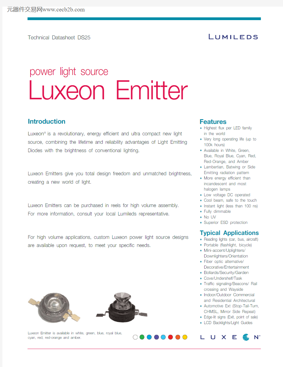
Luxeon Emitter
Features
Highest flux per LED family in the world
Very long operating life (up to 100k hours)
Available in White, Green,Blue, Royal Blue, Cyan, Red,Red Orange, and Amber Lambertian, Batwing or Side Emitting radiation pattern More energy efficient than incandescent and most halogen lamps
Low voltage DC operated Cool beam, safe to the touch Instant light (less than 100 ns) Fully dimmable No UV
Superior ESD protection
Typical Applications
Reading lights (car, bus, aircraft) Portable (flashlight, bicycle) Mini accent/Uplighters/Downlighters/Orientation Fiber optic alternative/Decorative/Entertainment Bollards/Security/Garden Cove/Undershelf/Task
Traffic signaling/Beacons/ Rail crossing and Wayside
Indoor/Outdoor Commercial and Residential Architectural Automotive Ext (Stop Tail Turn,CHMSL, Mirror Side Repeat) Edge lit signs (Exit, point of sale) LCD Backlights/Light Guides
power light source
Luxeon Emitter is available in white, green, blue, royal blue,
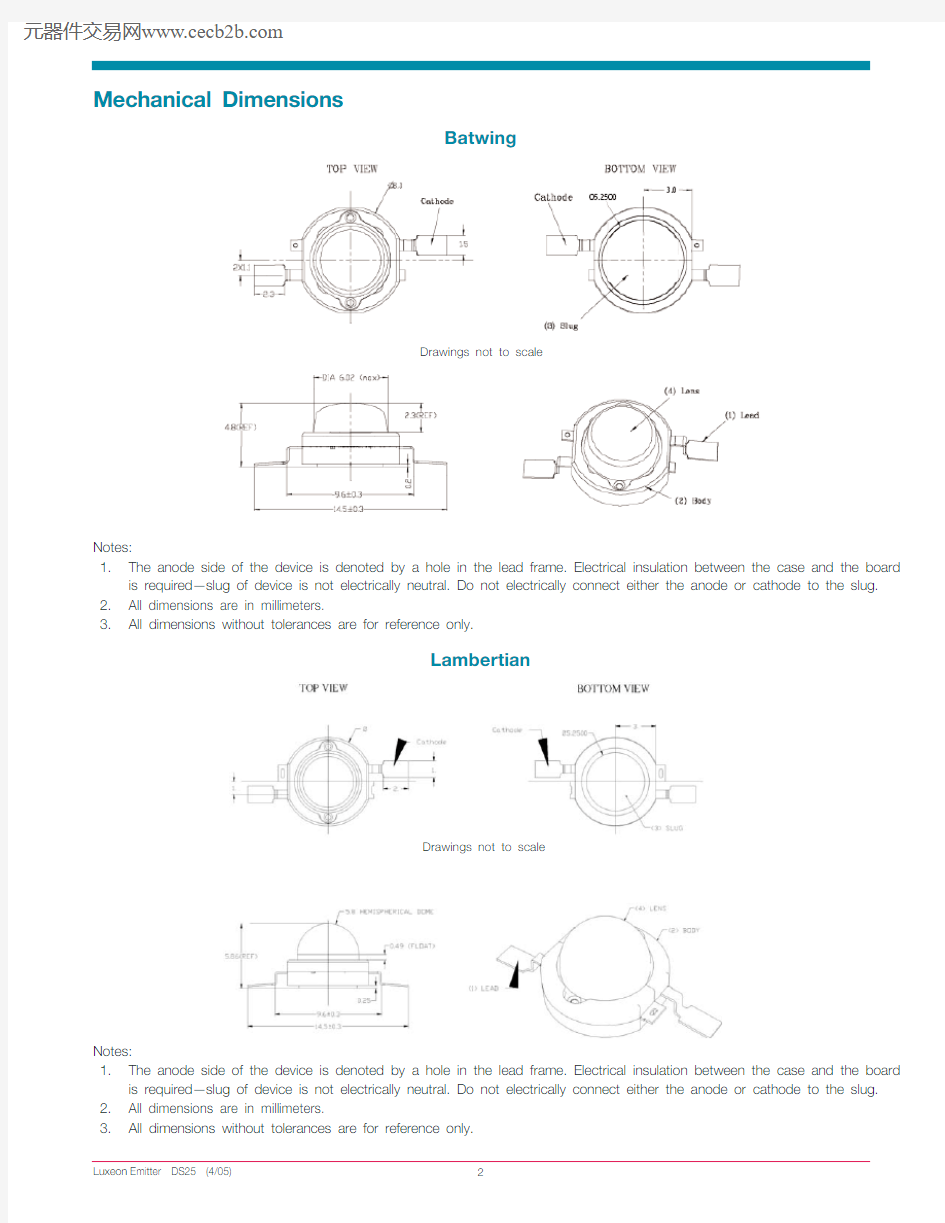
Mechanical Dimensions
Batwing
Drawings not to scale
Notes:
1.The anode side of the device is denoted by a hole in the lead frame. Electrical insulation between the case and the board
is required—slug of device is not electrically neutral. Do not electrically connect either the anode or cathode to the slug.
2.All dimensions are in millimeters.
3.All dimensions without tolerances are for reference only.
Lambertian
Drawings not to scale
Notes:
1.The anode side of the device is denoted by a hole in the lead frame. Electrical insulation between the case and the board
is required—slug of device is not electrically neutral. Do not electrically connect either the anode or cathode to the slug.
2.All dimensions are in millimeters.
Mechanical Dimensions, Continued
Side Emitting
Drawings not to scale
Notes:
1.The anode side of the device is denoted by a hole in the lead frame. Electrical insulation between the case and the board
is required—slug of device is not electrically neutral. Do not electrically connect either the anode or cathode to the slug.
2.Caution must be used in handling this device to avoid damage to the lens surfaces that will reduce optical efficiency.
3.All dimensions are in millimeters.
4.All dimensions without tolerances are for reference only.
Flux Characteristics at 350mA, Junction Temperature, T J= 25oC
Table 1.
M i n i m u m L u m i n o u s T y p i c a l L u m i n o u s
F l u x(l m)o r F l u x(l m)o r
R a d i o m e t r i c R a d i o m e t r i c
L u x e o n P o w e r(m W)P o w e r(m W)R a d i a t i o n
C o l o r E m i t t e rΦV[1,2]ΦV[2]P a t t e r n
White[5]LXHL BW0230.645
Warm White LXHL BW0313.920
Green LXHL BM0130.653
Cyan LXHL BE0130.645
Blue[3]LXHL BB018.216Batwing Royal blue[4]LXHL BR02145 mW220 mW
Red LXHL BD0113.927
Red LXHL BD0330.642
Red Orange LXHL BH0339.855
Amber LXHL BL0110.725
Amber LXHL BL0323.542
White LXHL PW0130.645
Green LXHL PM0130.653
Cyan LXHL PE0130.645
Blue[3]LXHL PB018.216Lambertian Royal Blue[4]LXHL PR03145 mW220 mW
Red LXHL PD0130.644
Red Orange LXHL PH0139.855
Amber LXHL PL0123.542
White LXHL DW0123.540.5
Green LXHL DM0123.548
Cyan LXHL DE0123.540.5
Blue[3]LXHL DB018.214.5Side Emitting Royal blue[4]LXHL DR01115 mW198 mW
Red LXHL DD0130.640
Red Orange LXHL DH0139.850
Amber LXHL DL0123.538
Notes for Table 1:
1.Minimum luminous flux or radiometric power performance guaranteed within published operating conditions. Lumileds
maintains a tolerance of ± 10% on flux and power measurements.
2.Luxeon types with even higher luminous flux levels will become available in the future. Please consult your Lumileds
Authorized Distributor or Lumileds sales representative for more information.
3.Minimum flux value for 470 nm devices. Due to the CIE eye response curve in the short blue wavelength range, the
minimum luminous flux will vary over the Lumileds' blue color range. Luminous flux will vary from a minimum of 6.3 lm at 460 nm to a typical of 20 lm at 480 nm due to this effect. Although the luminous power efficiency is lower in the short blue wavelength range, radiometric power efficiency increases as wavelength decreases. For more information, consult the Luxeon Design Guide, available upon request.
4.Royal Blue product is binned by radiometric power and peak wavelength rather than photometric lumens and
dominant wavelength.
5.In July 2003 Lumileds announced a second generation white batwing product using a new phosphor deposition process
resulting in improved color uniformity, LXHL BW02.
Optical Characteristics at 350mA, Junction Temperature, T J= 25oC
Table 2.
T e m p e r a t u r e
D o m i n a n t W a v e l e n g t h[1]λD,C o e f f i c i e n t o f T o t a l
P e a k W a v e l e n g t h[2]λP,S p e c t r a l D o m i n a n t I n c l u d e d V i e w i n g
o r C o l o r T e m p e r a t u r e[3]H a l f w i d t h[4]W a v e l e n g t h A n g l e[5]A n g l e[6]
R a d i a t i o n C C T(n m)(n m/o C)(d e g r e e s)(d e g r e e s) P a t t e r n C o l o r M i n.T y p.M a x.?λ1/2?λD/?T Jθ0.90V2θ1/2 White 4500K5500 K10000 K 110110 Warm White2850K3300K3800K 110110 Green520 nm530 nm550 nm350.04110110
Cyan490 nm505 nm520 nm300.04110110 Batwing Blue460 nm470 nm490 nm250.04110110 Royal Blue[2]440 nm455 nm460 nm200.04110110 Red620.5 nm625 nm645 nm200.05110110 Red Orange613.5 nm617 nm620.5nm200.06110110 Amber584.5 nm590 nm597 nm140.09110110
White4500 K5500 K10000 K 160140
Green520 nm530 nm550 nm350.04160140
Cyan490 nm505 nm520 nm300.04160140 Lambertian Blue460 nm470 nm490 nm250.04160140 Royal Blue[2]440 nm455 nm460 nm200.04160140 Red620.5 nm627 nm645 nm200.05160140 Red Orange613.5 nm617 nm620.5 nm200.06160140 Amber584.5 nm590 nm597 nm140.09160140
Optical Characteristics at 350mA, Junction Temperature, T J= 25oC, Cont.
Table 3.
T e m p e r a t u r e T y p i c a l
D o m i n a n t W a v e l e n g t h[1]λD,C o e f f i c i e n t o f T o t a l F l u x T y p i c a l
P e a k W a v e l e n g t h[2]λP,S p e c t r a l D o m i n a n t P e r c e n t A n g l e
o r C o l o r T e m p e r a t u r e[3]H a l f w i d t h[4]W a v e l e n g t h w i t h i n o f P e a k
R a d i a t i o n C C T(n m)(n m/o C)f i r s t45°[7]I n t e n s i t y[8] P a t t e r n C o l o r M i n.T y p.M a x.?λ1/2?λD/?T J C u mΦ45°θP e a k White4500 K5500 K10000 K <15%75° 85°
Green520 nm530 nm550 nm350.04<15%75° 85°
Cyan490 nm505 nm520 nm300.04<15%75° 85°Side Emitting Blue460 nm470 nm490 nm250.04<15%75° 85°Royal Blue[2]440 nm455 nm460 nm200.04<15%75° 85°Red620.5 nm627 nm645 nm200.05<15%75° 85°Red Orange 613.5 nm617 nm620.5 nm200.06<15%75° 85°Amber584.5 nm590 nm597 nm140.09<15%75° 85°
Notes: (for Tables 2 & 3)
1.Dominant wavelength is derived from the CIE 1931 Chromaticity diagram and represents the perceived color. Lumileds
maintains a tolerance of ± 0.5nm for dominant wavelength measurements.
2.Royal Blue product is binned by radiometric power and peak wavelength rather than photometric lumens and dominant
wavelength. Lumileds maintains a tolerance of ± 2nm for peak wavelength measurements.
https://www.360docs.net/doc/1f2064040.html,T ±5% tester tolerance.
4.Spectral width at ? of the peak intensity.
5.Total angle at which 90% of total luminous flux is captured.
6.θ? is the off axis angle from lamp centerline where the luminous intensity is ? of the peak value.
7.Cumulative flux percent within ± 45° from optical axis.
Notes: (for Tables 2 & 3) Continued
9.CRI (Color Rendering Index) for White product types is 70. CRI for Warm White product type is 90 with typical R9value
of 70.
10.All red, red orange and amber products built with Aluminum Indium Gallium Phosphide (AlInGaP).
11.All white, warm white, green, cyan, blue and royal blue products built with Indium Gallium Nitride (InGaN).
12.Blue and Royal Blue power light sources represented here are IEC825 Class 2 for eye safety.
Electrical Characteristics at 350mA, Junction Temperature, T J= 25oC
Table 4.
T e m p e r a t u r e
C o e f f i c i e n t o f T h e r m a l
F o r w a r d R e s i s t a n c e,
F o r w a r d V o l t a g e V F[1]D y n a m i c V o l t a g e[3]J u n c t i o n
R a d i a t i o n(V)R e s i s t a n c e[2](m V/o C)t o C a s e
P a t t e r n C o l o r M i n.T y p.M a x.(?)R D?V F/?T J(o C/W)RθJ C White 2.79 3.42 3.99 1.0 2.015 Warm White 2.79 3.42 3.99 1.0 2.015 Green 2.79 3.42 3.99 1.0 2.015
Cyan 2.79 3.42 3.99 1.0 2.015
Blue 2.79 3.42 3.99 1.0 2.015 Batwing Royal Blue 2.79 3.42 3.99 1.0 2.015 Red (BD01) 2.31 2.85 3.27 2.4 2.015
Red (BD03) 2.31 2.95 3.51 2.4 2.018
Red Orange 2.31 2.95 3.51 2.4 2.018
Amber (BL01) 2.31 2.85 3.27 2.4 2.015
Amber (BL03) 2.31 2.95 3.51 2.4 2.018 White 2.79 3.42 3.99 1.0 2.015
Green 2.79 3.42 3.99 1.0 2.015
Cyan 2.79 3.42 3.99 1.0 2.015 Lambertian Blue 2.79 3.42 3.99 1.0 2.015 Royal Blue 2.79 3.42 3.99 1.0 2.015 Red 2.31 2.95 3.51 2.4 2.018 Red Orange 2.31 2.95 3.51 2.4 2.018 Amber 2.31 2.95 3.51 2.4 2.018
White 2.79 3.42 3.99 1.0 2.015
Green 2.79 3.42 3.99 1.0 2.015
Cyan 2.79 3.42 3.99 1.0 2.015
Side Emitting Blue 2.79 3.42 3.99 1.0 2.015 Royal Blue 2.79 3.42 3.99 1.0 2.015 Red 2.31 2.95 3.51 2.4 2.018 Red Orange 2.31 2.95 3.51 2.4 2.018 Amber 2.31 2.95 3.51 2.4 2.018
Notes for Table 4:
1.Lumileds maintains a tolerance of ± 0.06V on forward voltage measurements.
2.Dynamic resistance is the inverse of the slope in linear forward voltage model for LEDs. See Figures 3a and 3b. Measured
between 25°C ≤T J≤110°C at I F= 350mA.
Absolute Maximum Ratings
Table 5.
W h i t e/G r e e n/R e d/
C y a n/B l u e/W a r m R e d O r a n g e/
P a r a m e t e r R o y a l B l u e W h i t e A m b e r DC Forward Current (mA) [1]350350385 Peak Pulsed Forward Current (mA)500500550
Average Forward Current (mA)350350350 ESD Sensitivity [2]± 16,000V HBM
LED Junction Temperature (°C)135120120 Storage Temperature (°C) 40 to +120 40 to +120 40 to +120
Soldering Temperature (°C) [3]260 for 5260 for 5260 for 5
seconds max seconds max seconds max
Notes for Table 5:
1.Proper current derating must be observed to maintain junction temperature below the maximum. For more information,
consult the Luxeon Design Guide, available upon request.
2.LEDs are not designed to be driven in reverse bias. Please consult Lumileds' Application Brief AB11 for further information.
3.Measured at leads, during lead soldering and slug attach, body temperature must not exceed 120°C. Luxeon emitters
cannot be soldered by general IR or Vapor phase reflow, nor by wave soldering. Lead soldering is limited to selective heating of the leads, such as by hot bar reflow, fiber focussed IR, or hand soldering. The package back plane (slug) may not be attached by soldering, but rather with a thermally conductive adhesive. Electrical insulation between the slug and the board is required. Please consult Lumileds' Application Brief AB10 on Luxeon Emitter Assembly Information for further details on assembly methods.
Wavelength Characteristics, T J = 25oC
Figure 1b. White Color Spectrum of Typical CCT Part, Integrated Measurement. Applicable for LXHL BW02.
0.00.20.40.60.81.0
350
400450500550600650700750800
Wavelength (nm)
R e l a t i v e S p e c r t a l P o w e r D i s t r i b u t i o n
0.00.20.40.60.81.0350
400450500
550600650700750800
Wavelength (nm)
R e l a t i v e S p e c t r a l P o w e r D i s t r i b u t i o
n
Figure 1a. Relative Intensity vs. Wavelength
Light Output Characteristics
5060708090100110120130140150-20
020406080100120
Junction T em perature, T J (o C )
R e l a t i v e L i g h t O u t p u t (%)
Figure 2a. Relative Light Output vs. Junction Temperature for White, Warm White, Green, Cyan, Blue and Royal Blue.
Figure 2b. Relative Light Output vs. Junction Temperature
for Red, Red Orange and Amber.
-20
020406080100120
Junction Tem perature, T J (o C )
R e l a t i v e L i g h t O u t p u t (%
Forward Current Characteristics, T J = 25oC
Note:
Driving these high power devices at currents less than the test conditions may produce unpredictable results and may be subject to variation in performance. Pulse width modulation (PWM) is recommended for dimming effects.
501001502002503003504000.00.5 1.0 1.5 2.0 2.5 3.0 3.5
V F - Forw ard Voltage (Volts)
I F - A v e r a g e F o r w a r d C u r r e n t (m A )
Figure 3b. Forward Current vs. Forward Voltage
for Red, Red Orange and Amber.
050100 150 200 250 300 350 400
0.00.5 1.0 1.5 2.0 2.5 3.0 3.5 4.0
V F
- Forward Voltage (Volts)
I F
- A v e r a g e F o r w a r d C u r r e n t (m A )
Figure 3a. Forward Current vs. Forward Voltage for White,
Warm White, Green, Cyan, Blue, and Royal Blue.
Forward Current Characteristics, T J = 25oC, Continued
Note:
Driving these high power devices at currents less than the test conditions may produce unpredictable results and may be subject
to variation in performance. Pulse width modulation (PWM) is recommended for dimming effects.
0.0
0.20.40.60.81.01.20100200300400I F - Average Forw ard C urrent (m A)
N o r m a l i z e d R e l a t i v e L u m i n o u s F l u x
Figure 4b. Relative Luminous Flux vs. Forward Current for Red, Red Orange and Amber at T J = 25oC maintained.
00.20.40.60.811.20
100
200
300
400
I F - Average Forw ard C urrent (mA)
N o r m a l i z e d R e l a t i v e L u m i n o u s F l u x
Figure 4a. Relative Luminous Flux vs. Forward Current for White, Warm White, Green, Cyan, Blue, and Royal Blue at T J = 25oC maintained.
Current Derating Curves
Derating based on T JMAX= 135oC for White, Green, Cyan, Blue, and Royal Blue.
Derating based on T JMAX= 120oC for Red, Red Orange and Amber.
Figure 5c. Maximum Forward Current vs. Ambient Temperature.
Typical Batwing Representative Spatial Radiation Pattern
Note:
For more detailed technical information regarding Luxeon radiation patterns, please consult your Lumileds Authorized Distributor
or Lumileds sales representative.
102030405060708090100-100-80-60-40-20
020*********
Angular D isplacem ent (D egrees)
R e l a t i v e I n t e n s i t y (%)
Figure 6a. Typical Representative Spatial Radiation Pattern
for Luxeon Emitter Warm White (LXHL BW03).
Figure 6b. Typical Representative Spatial Radiation Pattern for Luxeon Emitter Green, Cyan, Blue and Royal Blue.
Figure 6c. Typical Representative Spatial Radiation Pattern
Typical Batwing Representative Spatial Radiation Pattern, Continued
Note:
For more detailed technical information regarding Luxeon radiation patterns, please consult your Lumileds Authorized Distributor or Lumileds sales representative.
Figure 6d. Typical Representative Spatial Radiation Pattern
for Luxeon Emitter Red (LXHL BD01) and Amber (LXHL BL01).
Figure 6e. Typical Representative Spatial Radiation Pattern
for Luxeon Emitter Red (LXHL BD03), Red Orange (LXHL BH03) and Amber (LXHL BL03).
Typical Lambertian Representative Spatial Radiation Pattern
Note:
For more detailed technical information regarding Luxeon radiation patterns, please consult your Lumileds Authorized Distributor or Lumileds sales representative.
Typical Side Emitting Representative Spatial Radiation Pattern
Figure 7a. Typical Representative Spatial Radiation Pattern
for Luxeon Emitter Red, Red Orange and Amber.
102030405060708090100-100-80-60-40-200204060
80100
Angular Displacem ent (Degrees)
R e l a t i v e I n t e n s i t y (%)
Figure 8a. Typical Representative Spatial Radiation Pattern
102030405060708090
100-120-100-80
-60
-40
-20
20
40
60
80
100120
Angular Displacement (Degrees)
R e l a t i v e I n t e n s i t y (%)
Figure 7b. Typical Representative Spatial Radiation Pattern for Luxeon Emitter White, Green, Cyan, Blue and Royal Blue.
-100-80-60-40-20020406080100Angular Displacment (Degrees)
R e l a t i v e I n t e n s i t y (%)
Typical Side Emitting Representative Spatial Radiation Pattern, Continued
Average Lumen Maintenance Characteristics
Lifetime for solid state lighting devices (LEDs) is typically defined in terms of lumen maintenance—the percentage of initial light output remaining after a specified period of time. Lumileds projects that Luxeon products will deliver on average 70% lumen maintenance at 50,000 hours of operation. This performance is based on independent test data, Lumileds historical data from tests run on similar material systems, and internal Luxeon reliability testing. This projection is based on constant current 350 mA operation with junction temperature maintained at or below 90°C. Observation of design limits included in this data sheet is required in order to achieve this projected lumen maintenance.
Figure 8b. Typical Representative Spatial Radiation Pattern
for Luxeon Emitter White, Green, Cyan, Blue and Royal Blue.
102030405060708090
100-120-100-80
-60
-40
-20
20
40
60
80
100120
Angular Displacement (Degrees)
R e l a t i v e I n t e n s i t y (%)
Figure 9. Reel dimensions and orientation.
Batwing
Figure 10. Tape dimensions for Batwing radiation pattern.
Notes:
1.Luxeon emitters should be picked up by the body (not the lens) during placement. The inner diameter of the pick up collet
should be greater than or equal to 6.5 mm. Please consult Lumileds Application Brief AB10 on Luxeon Emitter assembly information for further details on assembly methods.
2.Drawings not to scale.
3.All dimensions are in millimeters.
Notes:
1.Luxeon emitters should be picked up by the body (not the lens) during placement. The inner diameter of the pick up collet
should be greater than or equal to 6.5 mm. Please consult Lumileds Application Brief AB10 on Luxeon Emitter assembly information for further details on assembly methods.2.Drawings not to scale.
3.All dimensions are in millimeters.
Figure 11. Reel dimensions and orientation.
Lambertian Side Emitting
Figure 12. Tape dimensions for Lambertian and
Side Emitting radiation patterns.