fe-safe success brief - Volvo Trucks 2010
Innovation in power
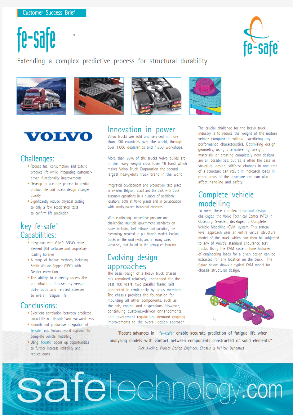
Volvo trucks are sold and serviced in more than 130 countries over the world, through over 1,000 dealerships and 1,800 workshops.More than 95% of the trucks Volvo builds are in the heavy weight class (over 16 tons) which makes Volvo Truck Corporation the second largest heavy-duty truck brand in the world.Integrated development and production take place in Sweden, Belgium, Brazil and the USA, with truck assembly operations in a number of additional locations, both at Volvo plants and in collaboration with locally-owned industrial concerns. With continuing competitive pressure and challenging multiple government standards on issues including fuel mileage and pollution, the technology required to put Volvo’s market leading trucks on the road rivals, and in many cases surpasses, that found in the aerospace industry.
Evolving design approaches
The basic design of a heavy truck chassis has remained relatively unchanged for the past 100 years: two parallel frame rails connected intermittently by cross members.The chassis provides the foundation for mounting all other components, such as the cab, engine, and suspensions. However,continuing customer-driven enhancements and government regulations demand ongoing improvements to the overall design approach.
The crucial challenge for the heavy truck
industry is to reduce the weight of the mature vehicle components without sacrificing any performance characteristics. Optimising design geometry, using alternative lightweight
materials, or creating completely new designs are all possibilities; but as is often the case in structural design, stiffness changes in one area of a structure can result in increased loads in other areas of the structure and can also affect handling and safety.
Complete vehicle modelling
To meet these complex structural design
challenges, the Volvo Technical Center (VTC) in G?teborg, Sweden, developed a Complete Vehicle Modelling (CVM) system. This system level approach uses an entire virtual structural model of the truck which can then be subjected to any of Volvo’s standard endurance test tracks. Using the CVM system, time histories of engineering loads for a given design can be extracted for any location on the truck. The figure below shows a typical CVM model for chassis structural design.
Challenges:
?Reduce fuel consumption and extend product life while integrating customer-driven functionality improvements ?Develop an accurate process to predict product life and assess design changes quickly
?Significantly reduce physical testing to only a few accelerated tests to confirm life prediction
k ey fe-safe
?
Capabilities:
?Integration with Volvo’s ANSYS Finite Element (FE) software and proprietary loading libraries
?A range of fatigue methods, including Smith-Watson-Topper (SWT) with Neuber correction
?The ability to correctly assess the contribution of assembly versus duty-loads and related stresses to overall fatigue life
Conclusions:
?E xcellent correlation between predicted product life in fe-safe ?and real-world tests ?Smooth and productive integration of fe-safe ?into Volvo’s hybrid approach to complete vehicle modelling
?Using fe-safe ? opens up opportunities to further increase reliability and reduce costs
Customer Success Brief
“Recent advances in fe-safe ?enable accurate prediction of fatigue life when analysing models with contact between components constructed of solid elements.”
Rick Aveline, Project Design Engineer, Chassis & Vehicle Dynamics
fe-safe
?
Extending a complex predictive process for structural durability
Extending CVM for durability:
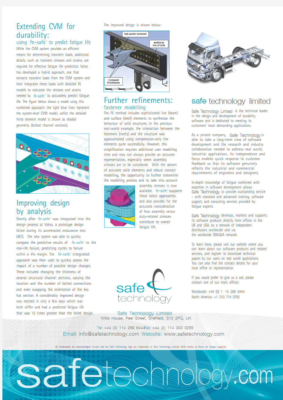
using fe-safe?to predict fatigue life While the CVM system provides an efficient means for determining transient loads, additional details, such as transient stresses and strains, are required for effective fatigue life prediction. Volvo has developed a hybrid approach, one that extracts transient loads from the CVM system and then integrates these loads with detailed FE models to calculate the stresses and strains needed by fe-safe?to accurately predict fatigue life. The figure below shows a model using this combined approach: the light blue lines represent the system-level CVM model, whilst the detailed finite element model is shown as shaded geometry (bolted channel sections).
Improving design
by analysis
Shortly after fe-safe?was integrated into the design process at Volvo, a prototype design failed during its accelerated endurance test (AET). The new system was able to quickly compare the predictive results of fe-safe?to the real-life failure, predicting cycles to failure within a 4% margin. The fe-safe?integrated approach was then used to quickly assess the impact of a number of possible design changes. These included changing the thickness of several structural channel sections, varying the location and the number of bolted connections and even swapping the orientation of the key hat section. A considerably improved design was realised in only a few days which was both stiffer and had a predicted fatigue life
that was 12 times greater than the failed design.Safe Technology Limited
Willis House, Peel Street, Sheffield, S10 2PQ, UK
Tel:+44 (0) 114 268 6444Fax:+44 (0) 114 303 0055
Email:info@https://www.360docs.net/doc/1d4728244.html, Website: https://www.360docs.net/doc/1d4728244.html,
All trademarks are acknowledged. fe-safe and the Safe Technology logo are trademarks of Safe Technology Limited. With thanks to Volvo for images supplied.
The improved design is shown below:
Further refinements:
fastener modelling
The FE method includes sophisticated line (beam)
and surface (shell) elements to synthesize the
behaviour of solid structures. In the previous
real-world example, the interaction between the
fasteners (rivets) and the structure was
approximated using compression-only line
elements quite successfully. However, this
simplification requires additional user modelling
time and may not always provide an accurate
representation, especially when assembly
stresses are to be considered. With the advent
of accurate solid elements and robust contact
modelling, the opportunity to further streamline
the modelling process and to take into account
assembly stresses is now
available. fe-safe? supports
these latest approaches
and also provides for the
accurate consideration
of how assembly versus
duty-related stresses
contribute to overall
fatigue life.
safe technology limited
Safe T echnology Limited is the technical leader
in the design and development of durability
software and is dedicated to meeting its
customers' most demanding applications.
As a private company, Safe Technology is
able to take a long-term view of software
development and the research and industry
collaboration needed to address real world,
industrial applications. Its independence and
focus enables quick response to customer
feedback so that its software genuinely
reflects the industrial and commercial
requirements of engineers and designers.
In-depth knowledge of fatigue combined with
expertise in software development allows
Safe T echnology to provide outstanding service
- with standard and advanced training, software
support, and consulting services provided by
fatigue experts.
Safe T echnology develops, markets and supports
its software products directly from offices in the
UK and USA, by a network of independent
distributors worldwide and via
the worldwide SIMULIA network.
To learn more, please visit our website where you
can learn about our software products and related
services, and register to download technical
papers by our users on real world applications.
You can also find the contact details for your
local office or representative.
If you would prefer to give us a call, please
contact one of our main offices:
Worldwide: +44 (0) 114 268 6444
North America: +1 310 714 0792