DCSFY-37S-K87-F204中文资料
IDC contacts
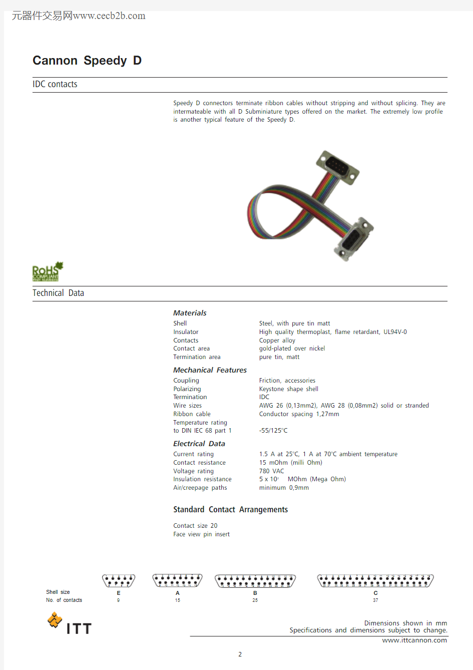
Speedy D connectors terminate ribbon cables without stripping and without splicing. They are
intermateable with all D Subminiature types offered on the market. The extremely low profile
is another typical feature of the Speedy D.
Technical Data
Materials
Shell Steel, with pure tin matt
Insulator High quality thermoplast, flame retardant, UL94V-0
Contacts Copper alloy
Contact area gold-plated over nickel
Termination area pure tin, matt
Mechanical Features
Coupling Friction, accessories
Polarizing Keystone shape shell
T ermination IDC
Wire sizes AWG 26 (0,13mm2), AWG 28 (0,08mm2) solid or stranded
Ribbon cable Conductor spacing 1,27mm
Temperature rating
to DIN IEC 68 part 1-55/125°C
Electrical Data
Current rating 1.5 A at 25°C, 1 A at 70°C ambient temperature
Contact resistance15 mOhm (milli Ohm)
Voltage rating780 VAC
Insulation resistance5x103MOhm (Mega Ohm)
Air/creepage paths minimum 0,9mm
Standard Contact Arrangements
Contact size 20
Face view pin insert
Shell size No. of contacts E
9
A
15
B
25
C
37
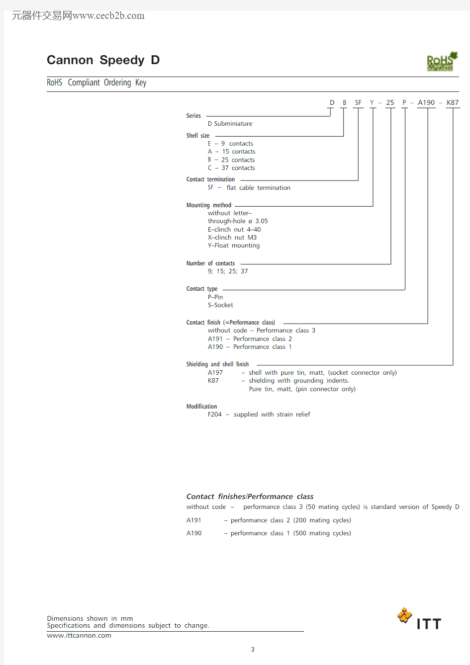
RoHS Compliant Ordering Key
D B SF Y–25P–A190–K87
Series
D Subminiature
Shell size
E– 9 contacts
A–15 contacts
B–25 contacts
C–37 contacts
Contact termination
SF–flat cable termination
Mounting method
without letter–
through-hole ? 3.05
E–clinch nut 4–40
X–clinch nut M3
Y–Float mounting
Number of contacts
9; 15; 25; 37
Contact type
P–Pin
S–Socket
Contact finish (=Performance class)
without code – Performance class 3
A191–Performance class 2
A190–Performance class 1
Shielding and shell finish
A197–shell with pure tin, matt, (socket connector only)
K87–shielding with grounding indents.
Pure tin, matt, (pin connector only)
Modification
F204–supplied with strain relief
Contact finishes/Performance class
without code–performance class 3 (50 mating cycles) is standard version of Speedy D
A191–performance class 2 (200 mating cycles)
A190–performance class 1 (500 mating cycles)
Pin connector / Socket connector
A B C
D E
No. of contacts ±0,3±0,3±0,159P 30,825,016,819,48x 1,27 = 10,18S 30,825,016,2519,415P 39,133,325,127,714 x 1,27 = 17,78S 39,133,324,5527,725P 53,047,038,8541,424 x 1,27 = 30,48S 53,047,038,341,437
P 69,363,555,357,936 x 1,27 = 45,72
S
69,3
63,5
54,75
57,9
P–Pin S–Socket
Mounting methods
Dimensions
Standard Through-hole
E
Clinch nut 4-40UNC
X
Clinch nut M3
Y
dual float mount
?2,26 ±
IDC contacts
Receptacle
No. of
contacts Through-hole Float mount Clinch nut 4–40*
9DESF-9S-A197DESFY-9S-A197DESFE-9S-A197
15DASF-15S-A197DASFY-15S-A197DASFE-15S-A197
25DBSF-25S-A197DBSFY-25S-A197DBSFE-25S-A197
37DCSF-37S-1A97DCSFY-37S-A197DCSFE-37S-A197
or metric thread replace E by X
Plugs
(pin connector only)
No. of
contacts with grounding indents Float mount Clinch nut 4–40*
9DESF-9P-K87DESFY-9P-K87DESFE-9P-K87
15DASF-15P-K87DASFY-15P-K87DASFE-15P-K87
25DBSF-25P-K87DBSFY-25P-K87DBSFE-25P-K87
37DCSF-37P-K87DCSFY-37P-K87DCSFE-37P-K87
or metric thread replace E by X
Performance class
Performance class 1: A190 into order ref.
Performance class 2: A191 into order ref.
e.g.DESF—9P-A190-K87 or
DESF—9S-A191-A197
Cable strain relief
No. of contact Order No.
9029-8757-009
15029-8757-015
25029-8758-025
37029-8757-037
Mounting combinations
A
B
C
H
Fig.Size Pin Socket +0,76+0,76+0,76_0,76/-01A A,E Standard Standard 6,357,636,996,991B B, C, D Standard Standard 6,047,717,066,682A, E Standard float 5,53–6,18–2B, C, D Standard float 5,23–6,25–2A,E float Standard 5,53–6,18–2B, C, D float Standard 5,23–5,87–3A, E Standard float –8,597,95–3B, C, D Standard float –8,667,64–3A, E float Standard –8,597,95–3
B, C, D
float
Standard
–
8,51
7,87
–
Remark:
A,B, C and H are dimensions between panels and represent the recommended limit to be used in the design of the connector mounting method.Standard pin assemblies contain 0,38 mm thick front shells on E and A sizes and 0,61 mm thick
shells on B, C and D sizes.
Pin Socket
front mount
rear mount
front mount
rear mount
Pin
Socket
front mount
rear mount
front mount
rear mount
Pin Socket
front mount
rear mount
front float mount
rear float mount Pin
Socket
front mount
rear mount
front float mount
front float mount
Figure 1A
Figure 1B
Figure 2
Figure 3
Panel cut-outs
A
B
Front Mounting Cutout Rear Mounting Cutout
Standard R
F
Panel
Standard
float mount
Code Y
R
F
F–front mounting
R–rear mounting
mounting A B C D rad. E no. of contacts±0,2±0,2±0,2+0,1±0,2 9front22,225,013,03,02,1
rear20,525,011,43,03,4
15front30,533,313,03,03,4
rear28,833,311,43,03,4
25front44,347,013,03,02,1
rear42,547,011,43,03,4
37front60,763,513,03,02,1
rear59,163,511,43,03,4
50front58,361,115,83,02,1
rear56,361,114,93,03,4
float A B C D rad. E No. of contacts mounting±0,2±0,2±0,2+0,1±0,2 9front23,025,013,82,22,1
rear21,325,012,22,23,4
15front31,333,313,82,22,1
rear29,633,312,22,23,4
25front45,147,013,82,22,1
rear43,347,012,22,23,4
37front61,563,513,82,22,1
rear59,863,512,22,23,4
50front59,261,116,62,22,1
rear57,161,114,92,23,4 Mounting