three-dimensional crack propagation

Acta Mechanica Solida Sinica,Vol.23,No.3,June,2010ISSN0894-9166 Pu b l ish e d by A M S S Press,Wu h a n,Ch i n a
FINITE ELEMENT MODELLING OF COMPLEX3D STATIC AND DYNAMIC CRACK PROPAGATION BY EMBEDDING COHESIVE ELEMENTS IN ABAQUS??
X i ang t ing Su1,2Z h e n jun Yang2?Guohua Liu1
(1College of Civil Engineering and Architecture,Zhejiang University,Hangzhou310027,China) (2Department of Engineering,the University of Liverpool,L693GQ,UK)
Received23November2009;revision received25May2010
ABSTRACT This study proposes an algorithm of embedding cohesive elements in Abaqus and
develops the computer code to model3D complex crack propagation in quasi-brittle materials in
a relatively easy and e?cient manner.The cohesive elements with softening traction-separation
relations and damage initiation and evolution laws are embedded between solid elements in re-
gions of interest in the initial mesh to model potential cracks.The initial mesh can consist of
tetrahedrons,wedges,bricks or a mixture of these elements.Neither remeshing nor objective
crack propagation criteria are needed.Four examples of concrete specimens,including a wedge-
splitting test,a notched beam under torsion,a pull-out test of an anchored cylinder and a notched
beam under impact,were modelled and analysed.The simulated crack propagation processes and
load-displacement curves agreed well with test results or other numerical simulations for all the
examples using initial meshes with reasonable densities.Making use of Abaqus’s rich pre/post-
processing functionalities and powerful standard/explicit solvers,the developed method o?ers a
practical tool for engineering analysts to model complex3D fracture problems.
KEY WORDS?nite element method,cohesive elements,three-dimensional crack propagation,
discrete crack model,concrete structures,Abaqus
I.INTRODUCTION
Crack propagation is an inherent feature in quasi-brittle materials such as concrete due to the low material tensile strength,and it is a predominant source of nonlinearity and a main culprit for ultimate failure of structures made from these materials.Accurate understanding of the crack propagation behaviour so as to assess the structural load-carrying capacity,by either experimental studies or numerical modelling,remains a worldwide challenge,especially for three-dimensional(3D)problems with complex geometries and loading conditions.
Numerical modelling of crack propagation has been an active research?eld since1960s[1,2].Nowadays there exist a large number of numerical models.In terms of how the cracks are modelled geometrically, there are discrete crack models explicitly separating crack surfaces and modelling discontinuity,smeared crack models based on continuum mechanics,and more indirectly,lattice models.In terms of numerical methods,both the traditional?nite element methods(FEM)and boundary element methods(BEM)
·272·ACTA MECHANICA SOLIDA SINICA2010 have been widely applied to crack propagation modelling.Extensive literature review of these models and methods in2D problems has been given elsewhere[3–6].
It appears now that the discrete crack models,mostly based on the cohesive crack model(CCM)devel-oped in ductile materials by Barenblatt[7]and Dugdale[8]and in quasi-brittle materials by Hillerborg[9], are becoming more and more popular,because of their ability to model macroscopic cracks with strong discontinuity,the CCM’s capability of realistically representing the energy dissipation during fracture processes,and the ease of its implementation as cohesive interface elements(CIE)in the FEM and the BEM.In general,two types of approaches are used to model discrete cohesive crack propagation. The?rst type of approaches is based on sophisticated remeshing procedures that constantly change the meshes as cracks propagate[3,10–12].For problems with crack paths unknown a priori,objective crack propagation criteria are needed to judge when and in which direction a crack propagates.This usually involves calculation of stress intensity factors(SIFs)and stresses at crack tips,whose accuracy can only be ensured by?ne crack-tip meshes or using singular elements.This in turn exacerbates the complexity of the remeshing procedure.It is also very di?cult for the remeshing-based approaches to deal with complex crack propagation situations,such as multiple cracking and3D problems.Indeed,the success of the remeshing-based approaches has been largely limited to2D static fracture problems with single or a few cracks,although they are computationally e?cient because a relatively small number of nonlinear CIEs are inserted into the meshes.Another type of approaches pre-insert or pre-embed CIEs between the?nite elements in the initial meshes[6,13–15].Crack propagation is modelled by automatic opening and merging of the CIEs under applied loadings.Neither remeshing procedures nor crack prop-agation criteria are needed so complex crack propagation can be modelled.However,these approaches restrict the cracks to the?nite element edges or surfaces and the predicted crack patterns may thus be mesh-dependent.Another disadvantage is the high computational cost due to the use of a large number of nonlinear CIEs.The CIEs can also be dynamically inserted when certain crack initiation criterion is satis?ed[16,17]so that the number of CIEs changes with the loading and the total number of CIEs remains relatively low.These procedures of dynamically inserting CIEs need objective crack initiation criteria and change meshes although the remeshing operation is relatively straightforward.
In the last two decades,the partition of unity?nite element method(PUFEM)[18,19]and the extended ?nite element method(XFEM)[20–22]are becoming popular in modelling crack propagation.These methods introduce discontinuity into the?nite elements.The crack growth is described independently of the mesh,so that remeshing is not needed.Meshless methods are also receiving much attention[23,24]. These innovative methods,showing high potential in crack propagation modelling,generally need?ne crack tip meshes like the traditional FEM to calculate accurate stresses or SIFs used in evaluating the crack propagation criterion.In this sense,?ne initial meshes are needed if the crack paths are unknown in priori,which means high computational cost.The newly-developed semi-analytical scaled boundary ?nite element[25]is able to compute accurate SIFs without using?ne meshes or singular elements.It has recently been applied to model discrete cohesive crack propagation[4,5,26],but so far only2D problems were modelled.
In summary,all the above crack models and numerical methods have their own advantages and disadvantages in terms of e?ectiveness,e?ciency and applicability,and the selection largely depends upon the problems analysed and the preference and experience of the analysts.Most of the existing studies have modelled2D crack propagation.3D modelling of complex cohesive crack propagation has been sporadically conducted,and there is a long way to go before it becomes a routine exercise in research and practical design due to the inherent di?culties.In addition,most of the studies have used specialised in-house computer programs(e.g.,Cornell University’s FRANC)that may be di?cult for practical engineers to use.Most of the general-purpose commercial FEA packages,such as Ansys and Abaqus,are unable to model complicated crack propagation without user intervention or second development.
This study aims at developing a practical?nite element method for modelling complex3D crack propagation in quasi-brittle materials under static and dynamic loadings.The method makes use of a special type of CIEs called‘cohesive elements’,designed for modelling bonded interfaces in Abaqus V6.5or higher[27],to model potential cracks.An e?cient algorithm was devised to insert these CIEs into concerned regions in FE meshes consisting of various types of solid elements.The method is simple to implement.The rich pre/post-processing functionalities and powerful implicit and explicit solvers
(a)Ameshwithoutcohesiveelements(b)Ameshwithcohesive
elementsinserted5
2
6
(C)Cohesiveelements
(COH3D8andCOH3D6)
2
5
Vol.23,No.3Xiangting Su et al.:Complex3D Static and Dynamic Crack Propagation·273·of Abaqus can be fully exploited.Its e?ectiveness is validated by modelling various fracture problems of concrete structures.
II.THE MODELLING METHOD
The proposed method involves the following steps:
(1)Meshing the domain using Abaqus/CAE and generating an input?le.
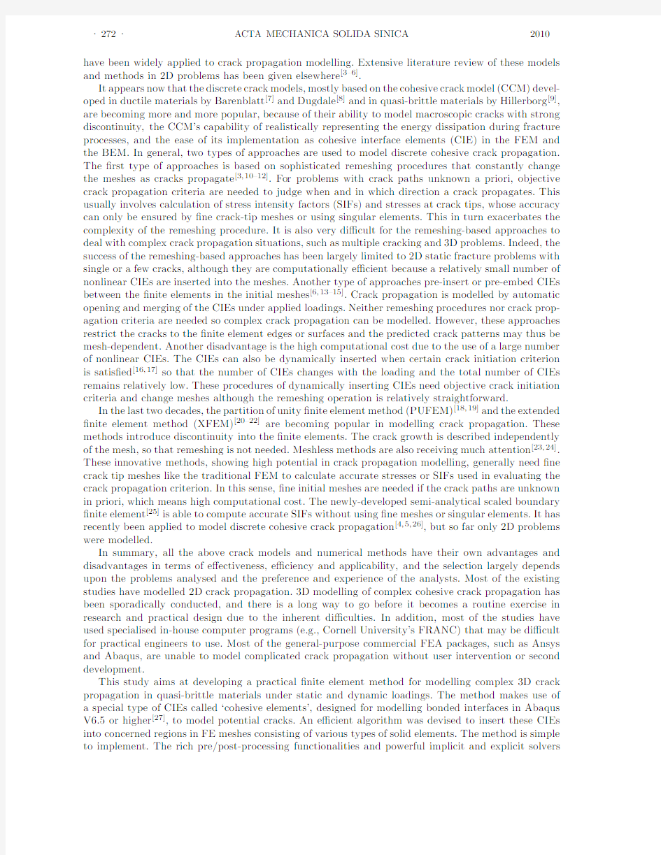
(2)Inserting cohesive elements into the regions of interest in the initial FE mesh using an in-house computer program and generating another input?le.The initial mesh may consist of solid elements such as4-noded tetrahedrons(C3D4),6-noded wedges(C3D6)and8-noded bricks(C3D8),or a mixture of these elements.Both6-noded and8-noded cohesive elements(COH3D6and COH3D8)can be inserted. Figure1shows a mesh with solid elements only,the mesh after CIEs are inserted and the3D CIEs, respectively.
(3)Solving the problem using Abaqus standard or explicit solvers.
This procedure can be readily automated by running a batch?le.The following brie?y discusses the key elements in the method.
Fig.1.FE meshes before and after cohesive elements are inserted and3D cohesive elements.
2.1.Cohesive Elements with Damage in Abaqus
The cohesive crack model[7–9]assumes the ex-
istence of a fracture process zone(FPZ)in front
of the real crack tip,in which energy dissipa-
tion occurs during fracture.In the FPZ,there
exist tractions in the normal direction(t n)and
the two tangential or shear directions(t s and t t)
across the crack surfaces,resulting from mech-
anisms such as material bonding,aggregate in-
terlocking and surface friction.Figure2shows a
curve relating the normal traction t n and the crack
opening displacementδn as an example.Similar
traction-separation curves can be de?ned for shear
tractions(t s and t t)-crack sliding displacements (δs andδt)relations.Before the crack initiates,a Fig.2An example of traction-separation curve with softening for cohesive elements.
linear elastic ascending phase is assumed to model the initially un-cracked material.After the crack initiates,the traction decreases monotonically as functions of the corresponding separation,which is often termed tension or strain softening.The initial tensile sti?ness k n0and the initial shear sti?ness k s0and k t0should be high enough to represent the un-cracked material,but not too high to cause numerical ill-conditioning.These initial sti?ness values are determined by a trial and error approach. Ifδn is negative during loading increments or iterations,a compressive sti?ness of magnitude equal to k n0is assigned in order to prevent penetration of crack surfaces.
·274·ACTA MECHANICA SOLIDA SINICA2010 The cohesive elements in Abaqus[27]are based on the cohesive crack model.The constitutive response of cohesive elements,de?ned in terms of traction-separation laws,assumes initially linear elastic behav-iour followed by the initiation and evolution of damage.Several damage initiation criteria are available in Abaqus.This study used the quadratic nominal stress criterion in all the examples.The damage evolution criteria can be classi?ed into three categories according to the relation between traction and separation:linear damage evolution,exponential damage evolution,and tabular damage evolution.All these criteria were used in this study.
2.2.Inserting Cohesive Elements into3D FE Meshes
Although inserting cohesive elements into2D FE meshes is relatively straightforward[6],it is not a trivial task for3D problems,especially if the FE mesh is not regular and consists of di?erent types of solid elements.One challenge is how to robustly deal with the changes in the complicated3D nodal and elemental connectivity due to the insertion of CIEs.This is tackled by an e?ective embedding algorithm implemented in a MATLAB[28]program with carefully designed data structures listed in Table1.It has the following steps:
Table1.Data structures used in the algorithm of inserting cohesive elements in3D meshes
index index index POINT elemindex
elemconn faceconn nodeconn isInDe?nedArea xcord
faceconn nodeconn elemconn ycord Members xcord type isBound zcord
ycord isInDe?nedArea newnodeindex
zcord
isInDe?nedArea
Vol.23,No.3Xiangting Su et al.:Complex 3D Static and Dynamic Crack Propagation ·275·
and CIEs are https://www.360docs.net/doc/1418636372.html,puter implementation of the above inserting algorithm must be carried out
with care,or the time spent on inserting CIEs may be unduly long.As an example,for an initial mesh
with 46800C3D8elements and 52140nodes,it takes about 30minutes for the developed MATLAB
program to insert 135,200CIEs using a PC with an Intel Xeon CPU@3.16GHz and 3GB physical
memory.
III.NUMERICAL EXAMPLES
Four 3D concrete structures subjected to static and dynamic loadings were modelled using the
developed method as examples.A PC with two Intel Xeon CPUs @3.16GHz and 3GB physical memory
was used.Both Abaqus/standard and explicit solvers were used to solve the nonlinear equation systems.
When the quasi-static explicit solver was used to model static problems,the analysis time was carefully
chosen to avoid dynamic e?ects.Because the failure mode of all the examples is mainly tensile fracture
and there is no experimental data about shear fracture resistance,the strength and the initial sti?ness
in shear are assumed as 10times those in tension for the cohesive elements so that shear fracture failure
does not occur.
3.1.Wedge-Splitting Test
The ?rst example is the wedge-splitting test of a concrete specimen CP250carried out by Trunk [29].
The test was modelled in 2D by Trunk [29]and Feist [30],and in 3D by Areias and Belytschko [22].The
geometry and the loading condition are shown in Fig.3.The concrete has a Young’s modulus E =28300
MPa,the Poisson ratio ν=0.2and mass density ρ=2.5×10?6kg/mm 3.A bilinear softening curve
shown in Fig.4with parameters obtained from the experiment was used to model the normal traction-
separation relation of the CIEs.The area under the curve is the fracture energy G f =0.49N/mm.The
initial sti?ness k n 0was assumed as 1×10⁵MPa ·mm.The Abaqus/explicit quasi-static solver used an
analysis time of 0.1
s.
Fig.3.Wedge-splitting test specimen (unit:
mm).
Fig. 4.Bilinear softening law used for the wedge-
splitting test.
Figure 5shows a deformed FE mesh with 774C3D6and 1392C3D8R solid elements,1854CIEs
and 6852nodes in total.It can be seen that the crack path was vertical as expected because of the
symmetry of the mesh and loading conditions.Finer meshes were also modelled but they led to little
di?erence from the predicted crack path and the load-crack mouth opening displacement (CMOD)
curves.Figure 6compares the load-CMOD curves from the experiment and modelling using di?erent
solvers and solid elements.The standard solver always failed by divergence at the post-peak stage,e.g.,
it failed at CMOD=3.2mm for C3D8as shown in Fig.6.This also often occurred in 2D simulations [6].
In contrast,the explicit solver always managed to model the whole fracture process when small enough
time increments were used.The explicit solver using C3D8R with reduced integration and hourglass
control (HC)resulted in nearly the same pre-peak responses as the standard solver using C3D8,while
the explicit solver using C3D8R but without hourglass control led to too soft pre-peak responses.C3D8
was also tried with the explicit solver but the computational time nearly doubled when C3D8R was
Z
_
焉
oJCrackmouthopeningdisplacement(mm)
·276·ACTA MECHANICA SOLIDA SINICA 2010
used.Therefore,the explicit solver was used in all the following simulations and C3D8R elements with
hourglass control were chosen when 8-noded brick elements were
used.
Fig.5.Deformed mesh (CMOD=4mm,
scale=100).Fig.6.Load-CMOD curves:e?ect of solid element types
and solvers.
Figure 7compares the load-CMOD curves from 3D and 2D simulations.In the 2D simula-tion,a similar mesh to the in-plane mesh of the 3D mesh (Fig.5)was used assuming a plane stress condition.It can be seen that the peak load pre-dicted from the 3D simulation is higher than that from the 2D,which re?ects the constraining e?ect of the specimen thickness.A very similar mesh to Fig.5but with a non-symmetric distribution of elements along the vertical central line was also modelled.The deformed mesh is shown in Fig.8.The crack path deviated from the central line,indicating the e?ect of the initial mesh.The
load-Fig.7Load-CMOD curves from 2D and 3D.CMOD curves predicted from the two meshes are shown in
Fig.9.
Fig.8.Deformed mesh from a non-symmetric mesh
(CMOD=4mm,
scale=100).Fig.9.Load-CMOD curves:e?ect of mesh arrangement.
3.2.Torsion Fracture Test
The second example is a concrete bar under torsion tested by Brokenshire [31].The geometry and the
loading condition are illustrated in Fig.10.3D modelling was carried out by Je?erson et al.[32]and Gasser
and Holzapfel [33].The three support points were assumed as ?xed and the loading incremental procedure
was controlled by the vertical displacement at the point C .The concrete has E =35000MPa,ν=0.2and
Vol.23,No.3Xiangting Su et al.:Complex3D Static and Dynamic Crack Propagation·277·
Fig.10.A concrete bar under torsion(unit:mm).
ρ=2.5×10?6kg/mm3.The same linear soften-
ing curve(Fig.11)as used in Ref.[32]was adopted
to model the normal traction-separation relation
with G f=0.08N/mm.The initial sti?ness was
set as k n0=7.5×10⁶MPa·mm.An analysis time
of0.3s was used in the explicit quasi-static pro-
cedure.CMOD is de?ned as the relative displace-
ment between the points A and B normal to the
notch surface(ref.Fig.10).Fig.11Linear softening law used for the torsion test.
Two FE meshes with di?erent solid element types were modelled to investigate the e?ect on the prediction of crack surfaces.Mesh A in Fig.12(a)has10651C3D4solid elements and9606CIEs,and Mesh B in Fig.12(b)has7027C3D8R and C3D6elements and8055CIEs.The predicted crack surfaces are compared with the test result in Fig.13.It is clear that Mesh A with C3D4led to very realistic, tortuous fracture surfaces whereas Mesh B with C3D8R predicted an unrealistically?at and smooth crack path.The predicted load-CMOD curves are presented in Fig.14.It can be seen that both meshes led to curves close to the experimental data.Mesh A predicted a peak load slightly higher than Mesh B.This may be explained by the predicted crack surfaces in Fig.13,where the tortuous and unsmooth crack surfaces from Mesh A o?er higher fracture resistance than the?at and smooth ones from Mesh B. Je?erson et al.[32]also modelled the same test using a similar mesh to Mesh B and the‘Craft’concrete
Fig.12.Two FE meshes used for the torsion test.
1)n。mthetestbyBrokenshire[13](b)C3D4mesh(c)C3D8mesh
·278·ACTA MECHANICA SOLIDA SINICA
2010
Fig.13.Crack surfaces after failure for the torsion
test.
Fig.14.Load-CMOD curves for the torsion
test.Fig.15.Pull-out test of a steel bar embedded in concrete
(unit:mm).
model.The predicted load-CMOD curve is also shown in Fig.14and it is very close to that from Mesh
B in this study.
3.3.Pull-out Test of a Steel-Embedded Concrete Anchor
This example models the pull-out behaviour of a steel anchor embedded in concrete.The detailed
geometry,applied boundary and loading conditions of one-quarter specimen are illustrated in Fig.15.
This example was also modelled in Ref.[19,22,23]using other methods.The anchor bolt,excluded from
the FE model,was simulated by a boundary condition of vertical displacement imposed on the
top
Fig.16.Meshes used for the pull-out test.
f
J
II
/(a)F=330kN,d=o.1iilm
/‘(c)F=307kN,d=o.26mm
,
/。(b)F=503kN,d=o.21mm(d)F=227kN,d=o.5mm
Vol.23,No.3Xiangting Su et al.:Complex3D Static and Dynamic Crack Propagation·279·surface of the groove.The concrete properties are:E=30000MPa,ν=0.2andρ=2.5×10?6kg/mm3.
A linear softening curve with G f=0.1N/mm,tensile strength=3MPa and k n0=6×10⁴MPa·mm was used.An analysis time of0.1s was used in the explicit solver.
To investigate the mesh-dependence of results,two meshes were modelled.The coarse mesh in Fig.16(a)has31889C3D4solid elements and60164CIEs,and the numbers for the?ne mesh in Fig.16(b) are69798and138169,respectively.Figure17shows the load(F)-displacement(d)curves from the two meshes and other studies.It can be seen that the two meshes predicted very close responses,especially the same failure point when the load suddenly dropped at d=0.25mm.
Fig.17.Load-displacement curves for the pull-out test.
Similar crack propagation processes and?nal crack patterns were predicted from the two meshes. Figure18illustrates four stages of the predicted crack propagation using the?ne mesh,where the cracks are represented by grey areas consisting of highly-damaged cohesive elements(with the damage Fig.18.Predicted crack propagation process of the pull-out test.
Z_焉
o
J
·280·ACTA MECHANICA SOLIDA SINICA 2010
index D ≥0.99).At F =310kN (60%of the peak load F u =503kN),tensile cracks initiated at
the top edge of the groove,forming a cone around the groove (Fig.18(a)).As the load approached
the peak,a splitting-mode longitudinal crack initiated at the top surface and propagated in the radial
direction (Fig.18(b)).Beyond the peak load (Fig.18(c)),the longitudinal crack propagated rapidly,
leading to a drastic decline on the load-displacement curve (Fig.17).After the complete propagation
of the longitudinal crack (Fig.18(d)),the conical crack continued to advance with the load decreasing
slowly.The simultaneous propagation of the longitudinal crack and the conical crack,observed in the
experiments by Rots [34],was well reproduced.This may explain the di?erence between the predicted
load-displacement curves (Fig.17)by the present study and other studies [22,23]which only modelled
the conical crack.
3.4.Impact Test of a Concrete Beam
The fourth example is a concrete beam under
impact tested and modelled in 2D by Du et al.[35].
3D modelling was reported by Belytschko et al.[36].
The geometry and the boundary condition are
shown in Fig.19.The impact load history obtained
from the test (Fig.20)was input as the loading
condition.The concrete properties are:E =34480MPa,ν=0.2and ρ=2.5×10?6kg/mm 3.
An
Fig.19Impact test of a concrete beam (unit:mm).exponential softening curve (Fig.21)with the exponential law parameter α=1.5and the equivalent
dynamic fracture energy G f =0.152N/mm,suggested in Ref.[35],was adopted to model the CIEs.
The initial sti?ness k n 0=1×10⁵MPa ·mm was used.
Figure 22shows a deformed mesh at the post-peak stage when t =1ms.The mesh consists of
3645solid elements and 606cohesive elements.Figure 23compares favourably the predicted load-
de?ection curve with the test data.Figure 24compares the measured and computed strain histories
at three locations (SG01,SG02and SG03).The strain history computed for SG03agreed well with
the measured.For the other two locations,the strain histories were underestimated,probably due to Fig.20.Load history used for the impact
test.
Fig.21.Exponential softening law for the impact
test.
Fig.22.Deformed mesh for the impact
test.
Fig.23.Load-displacement curves for the impact test.
Time(HIS)
一【’一口。∞岛①两.
Vol.23,No.3Xiangting Su et al.:Complex 3D Static and Dynamic Crack Propagation ·281·
the negligence of shrinkage e?ects in the numerical modelling [37].The crack-tip extension histories are
compared in
Fig.25.
Fig.24.Strain history for the impact
test.Fig.25.Crack-tip extension history for the impact test.
IV.CONCLUSIONS
A simple yet e?ective ?nite element methodology has been developed to simulate 3D complex cohesive
crack propagation in quasi-brittle materials,using Abaqus’s cohesive elements.An e?cient algorithm
to insert the cohesive elements into initial ?nite element meshes was devised and implemented by an
in-house computer program.Several concrete examples were modelled to demonstrate the e?ectiveness
of the method.It is concluded that,making use of the rich pre/post-processing functionalities and
powerful standard/explicit solvers in Abaqus,the developed methodology seems promising to provide
a practical simulation tool for modelling realistic 3D fracture in various industries.
References
[1]Scordelis,A.C.and Ngo,D.,Finite element analysis of reinforced concrete beams.Journal of the American
Concrete Institute ,1967,64:152-163.
[2]Rashid,Y.R.,Ultimate strength analysis of prestressed concrete pressure vessels.Nuclear Engineering and
Design ,1968,7(4):334-344.
[3]Yang,Z.J.and Chen,J.F.,Fully automatic modelling of cohesive discrete crack propagation in concrete
beams using local arc-length methods.International Journal of Solids and Structures ,2004,41(3-4):801-
826.
[4]Yang,Z.J.,Fully automatic modelling of mixed-mode crack propagation using scaled boundary ?nite element
method.Engineering Fracture Mechanics ,2006,73(12):1711-1731.
[5]Yang,Z.J.and Deeks,A.J.,Fully-automatic modelling of cohesive crack growth using a ?nite element-scaled
boundary ?nite element coupled method.Engineering Fracture Mechanics ,2007,74(16):2547-2573.
[6]Yang,Z.J.,Su,X.T.,Chen,J.F.and Liu,G.H.,Monte Carlo simulation of complex cohesive fracture in random
heterogeneous quasi-brittle materials.International Journal of Solids and Structures ,2009,46(17):3222-
3234.
[7]Barenblatt,G.I.,The formation of equilibrium cracks during brittle fracture:general ideas and hypothesis,
axially symmetric cracks.Applied Mathematics and Mechanics ,1959,23:622-636.
[8]Dugdale,D.S.,Yielding of steel sheets containing slits.Journal of Mechanics of Physics and Solids ,1960,
8:100-104.
[9]Hillerborg,A.,Modeer,M.and Petersson,P.,Analysis of crack formation and crack growth in concrete by
means of fracture mechanics and ?nite elements.Cement and Concrete Research ,1976,6:773-782.
[10]Wawrzynek,P.A.and Ingra?ea,A.R.,An interactive approach to local remeshing around a propagating
crack.Finite Elements in Analysis and Design ,1989,5:87-96.
[11]Xie,M.and Gerstle,W.H.,Energy-Based Cohesive Crack Propagation Modeling.Journal of Engineering
Mechanics-ASCE ,1995,121(12):1349-1358.
[12]Yang,Z.J.and Xu,X.F.,A heterogeneous cohesive model for quasi-brittle materials considering spatially
varying random fracture https://www.360docs.net/doc/1418636372.html,puter Methods in Applied Mechanics and Engineering ,2008,197:
4027-4039.
·282·ACTA MECHANICA SOLIDA SINICA2010 [13]Xu,X.P.and Needleman,A.,Numerical simulations of fast crack growth in brittle solids.Journal of the
Mechanics and Physics of Solids,1994,42(9):1397-1434.
[14]L′o pez,C.,Carol,I.and Aguado,A.,Meso-structural study of concrete fracture using interface elements.I:
numerical model and tensile behavior.Materials and Structures,2008,41(3):583-599.
[15]L′o pez,C.,Carol,I.and Aguado,A.,Meso-structural study of concrete fracture using interface elements.II:
compression,biaxial and Brazilian test.Materials and Structures,2008,41(3):601-620.
[16]Camacho,G.T.and Ortiz,M.,Computational modelling of impact damage in brittle materials.International
Journal of Solids and Structures,1996,33:2899-2938.
[17]Pandol?,A.and Ortiz,M.,An e?cient adaptive procedure for three-dimensional fragmentation simulations.
Engineering with Computers,2002,18:148-159.
[18]Melenk,J.M.and Babuska,I.,The partition of unity?nite element method:Basic theory and applications.
Computer Methods in Applied Mechanics and Engineering,1996,139:289-314.
[19]Gasser,T.C.and Holzapfel,G.A.,Modeling3D crack propagation in unreinforced concrete using PUFEM.
Computer Methods in Applied Mechanics and Engineering,2005,194:2859-2896.
[20]Moes,N.,Dolbow,J.and Belytschko,T.,A?nite element method for crack growth without remeshing.In-
ternational Journal for Numerical Methods in Engineering,1999,46:131-150.
[21]Dolbow,J.E.,An Extended Finite Element Method with Discontinuous Enrichment for Applied Mechanics.
Ph.D.dissertation,Northwestern University,1999.
[22]Areias,P.M.A.and Belytschko,T.,Analysis of three-dimensional crack initiation and propagation using the
extended?nite element method.International Journal for Numerical Methods in Engineering,2005,63: 760-788.
[23]Bordas,S.P,Rabczuk,T.and Zi,G.,Three-dimensional crack initiation,propagation,branching and junc-
tion in non-linear materials by an extended meshfree method without asymptotic enrichment.Engineering Fracture Mechanics,2008,75:943-960.
[24]Sun,H.T.and Wang,Y.H.,The meshless virtual boundary method and its applications to2D elasticity
problems.Acta Mechanica Solida Sinica,2007,20(1):30-40.
[25]Wolf,J.P.and Song,C.M.,Finite-element Modelling of Unbounded Media,Wiley,Chichester,1996.
[26]Ooi,E.T.and Yang,Z.J.,Modelling multiple cohesive crack propagation using a?nite element-scaled bound-
ary?nite element coupled method.Engineering Analysis with Boundary Elements,2009,33:915-929.
[27]Abaqus6.7User Documentation,Dessault Systems,2007.
[28]Matlab R2008a User’s Guide,MathWorks,2008.
[29]Trunk,B.,Ein?uss der Bauteilgroesse auf die Bruchenergie von Beton.Aedi?catio Publishers,2000(in
German).
[30]Feist,C.,Numerical Simulations of Localization E?ects in Plain Concrete.Ph.D.dissertation,University
Innsbruck,2003.
[31]Brokenshire,D.R.,A Study of Torsion Fracture Tests.Ph.D.Dissertation,Cardi?University,1996.
[32]Je?erson,A.D.,Barr,B.,Bennett,T.and Hee,S.,Three dimensional?nite element simulations of fracture
tests using the Craft concrete https://www.360docs.net/doc/1418636372.html,puters and Concrete,2004,1:261-284.
[33]Gasser,T.C.and Holzapfel,G.A.,3D Crack propagation in unreinforced concrete:A two-step algorithm for
tracking3D crack https://www.360docs.net/doc/1418636372.html,puter Methods in Applied Mechanics and Engineering,2006,195:5198-5219.
[34]Rots,J.G.,Computational Modelling of Concrete Fracture.Ph.D.Dissertation,Delft University of Tech-
nology,1988.
[35]Du,J.,Yon,J.H.,Hawkins,N.M.,Arakawa,K.and Kobayashi,A.S.,Fracture process zone for concrete for
dynamic loading.ACI Materials Journal,1992,89:252-258.
[36]Belytschko,T.,Organ,D.and Gerlach,C.,Element-free galerkin methods for dynamic fracture in concrete.
Computer Methods in Applied Mechanics and Engineering,2000,187:385-399.
[37]Yon,J.H.,Hawkins,N.M.and Kobayashi,A.S.,Strain-rate sensitivity of concrete mechanical properties.ACI
Materials Journal,1992,89:146-153.
FINITE ELEMENT MODELLING OF COMPLEX 3D STATIC AND DYNAMIC CRACK
PROPAGATION BY EMBEDDING COHESIVE ELEMENTS IN ABAQUS
作者:Xiangting Su, Zhenjun Yang, Guohua Liu
作者单位:Xiangting Su(College of Civil Engineering and Architecture,Zhejiang University,Hangzhou
310027,China;Department of Engineering,the University of Liverpool,L69 3GQ,UK), Zhenjun
Yang(Department of Engineering,the University of Liverpool,L69 3GQ,UK), Guohua Liu(College of
Civil Engineering and Architecture,Zhejiang University,Hangzhou 310027,China)
刊名:
固体力学学报(英文版)
英文刊名:ACTA MECHANICA SOLIDA SINICA
年,卷(期):2010,23(3)
参考文献(37条)
1.Areias,P.M.A;Belytschko,T Analysis of three-dimensional crack initiation and propagation using the extended finite element method[外文期刊] 2005(5)
2.Yang,Z.J;Chen,J.F Fully automatic modelling of cohesive discrete crack propagation in concrete beams using local arc-length methods[外文期刊] 2004(3-4)
3.Yang,Z.J;Xu,X.F A heterogeneous cohesive model for quasi-brittle materials considering spatially varying random fracture properties 2008
4.Xie,M;Gerstle,W.H Energy-Based Cohesive Crack Propagation Modeling[外文期刊] 1995(12)
5.Wawrzynek,P.A;Ingraffea,A.R An interactive approach to local remeshing around a propagating crack 1989
6.Hillerborg,A;Modeer,M;Petersson,P Analysis of crack formation and crack growth in concrete by means of fracture mechanics and finite elements[外文期刊] 1976
7.Dugdale,D.S Yielding of steel sheets containing slits 1960
8.Barenblatt,G.I The formation of equilibrium cracks during brittle fracture:general ideas and hypothesis,axially symmetric cracks 1959
9.Yang,Z.J;Su,X.T;Chen,J.F;Liu,G.H Monte Carlo simulation of complex cohesive fracture in random heterogeneous quasi-brittle materials 2009(17)
10.Yang,Z.J;Deeks,A.J Fully-automatic modelling of cohesive crack growth using a finite element-scaled boundary finite element coupled method[外文期刊] 2007(16)
11.Yang,Z.J Fully automatic modelling of mixed-mode crack propagation using scaled boundary finite element method[外文期刊] 2006(12)
12.Yon,J.H;Hawkins,N.M;Kobayashi,A.S Strain-rate sensitivity of concrete mechanical properties 1992
13.Belytschko,T;Organ,D;Gerlach,C Element-free galerkin methods for dynamic fracture in concrete[外文期刊] 2000(3-4)
14.Du,J;Yon,J.H;Hawkins,N.M;Arakawa,K.and Kobayashi,A.S Fracture process zone for concrete for dynamic loading 1992
15.Rots,J.G Computational Modelling of Concrete Fracture 1988
16.Gasser,T.C;Holzapfel,G.A3D Crack propagation in unreinforced concrete:A two-step algorithm for tracking 3D crack paths 2006
17.Jefferson,A.D;Barr,B;Bennett,T;Hee,S Three dimensional finite element simulations of fracture tests using the Craft concrete model 2004
18.Brokenshire,D.R A Study of Torsion Fracture Tests 1996
19.Feist,C Numerical Simulations of Localization Effects in Plain Concrete 2003
20.Trunk,B Einfiuss der Bauteilgroesse auf die Bruchenergie von Beton 2000
21.Matlab R2008a User's Guide,MathWorks 2008
22.Abaqus 6.7 User Documentation,Dessault Systems 2007
23.Ooi,E.T;Yang,Z.J Modelling multiple cohesive crack propagation using a finite element-scaled boundary finite element coupled method 2009
24.Wolf,J.P;Song,C.M Finite-element Modelling of Unbounded Media 1996
25.Sun,H.T;Wang,Y.H The meshless virtual boundary method and its applications to 2D elasticity problems[期刊论文]-Acta Mechanica Solida Sinica 2007(01)
26.Bordas,S.P;Rabczuk,T;Zi,G Threo-dimensional crack initiation,propagation,branching and junction in non-linear materials by an extended meshfree method without asymptotic enrichment[外文期刊] 2008(5)
27.Rashid,Y.R Ultimate strength analysis of prestressed concrete pressure vessels[外文期刊] 1968(04)
28.Scordelis,A.C;Ngo,D Finite element analysis of reinforced concrete beams 1967
29.Dolbow,J.E An Extended Finite Element Method with Discontinuous Enrichment for Applied Mechanics 1999
30.Moes,N;Dolbow,J;Belytschko,T A finite element method for crack growth without remeshing 1999
31.Gasser,T.C;Holzapfel,G.A Modeling 3D crack propagation in unreinforced concrete using PUFEM[外文期刊] 2005(25/26)
32.Melenk,J.M;Babuska,I The partition of unity finite element method:Basic theory and applications[外文期刊] 1996
33.Pandolfi,A;Ortiz,M An efficient adaptive procedure for three-dimensional fragmentation simulations[外文期刊] 2002(2)
34.Camacho,G.T;Ortiz,M Computational modelling of impact damage in brittle materials[外文期刊] 1996(20/22)
35.Lopez,C;Carol,I;Aguado,A Meso-structural study of concrete fracture using interface elements.Ⅱ:compression,biaxial and Brazilian test 2008(03)
36.Lopez,C;Carol,I;Aguado,A Meso-structural study of concrete fracture using interface elements.Ⅰ:numerical model and tensile behavior 2008(03)
37.Xu,X.P;Needleman,A Numerical simulations of fast crack growth in brittle solids 1994(09)
本文链接:https://www.360docs.net/doc/1418636372.html,/Periodical_gtlxxb-e201003010.aspx
蹭网工具WinAirCrackPack工具包使用介绍
使用蹭网工具WinAirCrackPack工具包\BT3 (BackTrack 3)破解 首先通过NetStumbler确认客户端已在某AP的覆盖区内,并通过AP信号的参数进行‘踩点’(数据搜集)。 NetStumbler 下载地址https://www.360docs.net/doc/1418636372.html,/downloads/ 通过上图的红色框框部分内容确定该SSID名为demonalex的AP为802.11b类型设备,Encryption属性为‘已加密’,根据802.11b所支持的算法标准,该算法确定为WEP。有一点需要注意:NetStumbler对任何有使用加密算法的STA[802.11无线站点]都会在Encryption属性上标识为WEP算法,如上图中SSID为gzpia的AP使用的加密算法是WPA2-AES。 破解下载Win32版AirCrack程序集---WinAirCrackPack工具包(下载地址:https://www.360docs.net/doc/1418636372.html,/download/wireless/aircrack/WinAircrackPack.zip)。解压缩后得到一个大概4MB的目录,其中包括六个EXE文件:aircrack.exe 原WIN32版aircrack程序airdecap.exe WEP/WPA解码程序 airodump.exe 数据帧捕捉程序Updater.exe WIN32版aircrack的升级程序 WinAircrack.exe WIN32版aircrack图形前端wzcook.exe 本地无线网卡缓存中的WEPKEY记录程序我们本次实验的目的是通过捕捉适当的数据帧进行IV(初始化向量)暴力破解得到WEP KEY,因此只需要使用airodump.exe(捕捉数据帧用)与WinAircrack.exe(破解WEP KEY用)两个程序就可以了。 首先打开ariodump.exe程序,按照下述操作:
WinAircrackPack-破解无线密码使用教程
WinAircrackPack 破解你邻居家的无线WIFI密码 破解静态WEP KEY全过程 发现 首先通过NetStumbler确认客户端已在某AP的覆盖区内,并通过AP信号的参数进行…踩点?(数据搜集)。 NetStumbler 下载地址https://www.360docs.net/doc/1418636372.html,/downloads/ 通过上图的红色框框部分内容确定该SSID名为demonalex的AP为802.11b类型设备,Encryption属性为…已加密?,根据802.11b所支持的算法标准,该算法确定为WEP。有一点需要注意:NetStumbler对任何有使用加密算法的STA[802.11无线站点]都会在Encryption 属性上标识为WEP算法,如上图中SSID为gzpia的AP使用的加密算法是WPA2-AES。 破解 下载Win32版AirCrack程序集---WinAirCrackPack工具包(下载地址:https://www.360docs.net/doc/1418636372.html,/download/wireless/aircrack/WinAircrackPack.zip)。解压缩后得到一个大概4MB的目录,其中包括六个EXE文件: aircrack.exe 原WIN32版aircrack程序 airdecap.exe WEP/WPA解码程序 airodump.exe 数据帧捕捉程序 Updater.exe WIN32版aircrack的升级程序 WinAircrack.exe WIN32版aircrack图形前端 wzcook.exe 本地无线网卡缓存中的WEPKEY记录程序 我们本次实验的目的是通过捕捉适当的数据帧进行IV(初始化向量)暴力破解得到WEP KEY,因此只需要使用airodump.exe(捕捉数据帧用)与WinAircrack.exe(破解WEP KEY 用)两个程序就可以了。 首先打开ariodump.exe程序,按照下述操作:
Aircrack-ng for Windows
教你利用Aircrack-ng for Windows破解WPA 2011-11-25 13:13 佚名 https://www.360docs.net/doc/1418636372.html, 我要评论(0)字号:T | T 由于在Windows环境下不能如Linux环境般直接调用无线网卡,所以需要使用其他工具将 无线网卡载入,以便攻击工具能够正常使用。在无线攻击套装Aircrack-ng的Windows版 本下内置了这样的工具,就是airserv-ng。 AD:2013云计算架构师峰会超低价抢票中由于在Windows环境下不能如Linux环境般直接调用无线网卡,所以需要使用其他工 具将无线网卡载入,以便攻击工具能够正常使用。在无线攻击套装Aircrack-ng的Windows版本下内置了这样的工具,就是airserv-ng。 步骤1:打开CMD,通过cd命令进入到aircrack-ngforWindows版本所在目录,输入airserv-ng,可以看到如图5-29所示的内容。 图5-29在CMD下运行airserv-ng 参数解释: *-p,指定监听的端口,即提供连接服务的端口,默认为666; *-d,载入无线网卡设备,需要驱动支持; *-c,指定启动工作频道,一般设置为预攻击AP的工作频道,默认为1; *-v,调试级别设定。 作为Windows下的破解,第一步就是使用airserv-ng来载入我们当前使用的无线网卡,为后续破解做准备,命令如下(注意:在命令中出现的引号一律使用英文下的引号输入):airserv-ng-d"commview.dll|debug" 或者
airserv-ng-d"commview.dll|{myadapterid}" 输入完成后airserv-ng会自动搜寻现有无线网卡,会有提示,选择正确的无线网卡直接输入y,此时airserv-ng就在正常载入驱动后,同时开始监听本地的666端口。换句话说,airserv-ng提供的是该无线网卡的网络服务,其他计算机上的用户也可以连接到这个 端口来使用这块网卡,如图5-30所示。 图5-30airserv-ng工作中 步骤2:现在可以使用airodump-ng来搜索当前无线环境了。注意,要另开启一个CMD,再输入如下命令: airodump-ng127.0.0.1:666 这里在IP地址处输入为本机即127.0.0.1,端口采用的是默认的666。 图5-31在CMD下运行airodump-ng 如图5-31所示,当确定预攻击目标AP的频道后,使用组合键Ctrl+C中断,即可使用如下参数来精确定位目标: airodump-ng--channelnumber-wfilename127.0.0.1:666 这里输入“airodump-ng--channel7-wonewpa127.0.0.1:666”,回车后可看到如图5-32所示的内容。
教你怎么破解别人的无线网络密码 手把手跟我操作就可以啦 很管用
如何破解无线网络密码 随着社会的进步!WIFI上网日益普及,特别是大城市中随便在一个小区搜索一下就能找到好多热点,搜索到热点然后链接上去那么我们就可以尽情的享受免费上网服务了。 不过除了公共场所以及菜鸟用户之外几乎所有的WIFI信号都是加密的,很简单换作是你你也不愿意把自己的带宽免费拿出来给别人用,所以如果你搜索到你附近有热点想免费上网的话请仔细往下学习... 破解静态WEP KEY全过程 首先通过NetStumbler确认客户端已在某AP的覆盖区内,并通过AP信号的参数进行‘踩点’(数据搜集)。
通过上图的红色框框部分内容确定该SSID名为demonalex的AP为802.11b类型设备,Encryption属性为‘已加密’,根据802.11b所支持的算法标准,该算法确定为WEP。有一点需要注意:NetStumbler对任何有使用加密算法的STA[802.11无线站点]都会在Encryption属性上标识为WEP算法,如上图中SSID为gzpia的AP使用的加密算法是WPA2-AES。 我们本次实验的目的是通过捕捉适当的数据帧进行IV (初始化向量)暴力破解得到WEP KEY,因此只需要使用airodump.exe(捕捉数据帧用)与WinAircrack.exe(破解WEP KEY用)两个程序就可以了。 首先打开ariodump.exe程序,按照下述操作:
首先程序会提示本机目前存在的所有无线网卡接口,并要求你输入需要捕捉数据帧的无线网卡接口编号,在这里我选择使用支持通用驱动的BUFFALO WNIC---编号 ‘26’;然后程序要求你输入该WNIC的芯片类型,目前大多国际通用芯片都是使用‘HermesI/Realtek’子集的,因此选择‘o’;然后需要输入要捕捉的信号所处的频道,我们需要捕捉的AP所处的频道为‘6’;提示输入捕捉数据帧后存在的文件名及其位置,若不写绝对路径则文件默认存在在winaircrack的安装目录下,以.cap 结尾,我在上例中使用的是‘last’; 最后winaircrack提示:‘是否只写入/记录IV[初始化向量]到cap文件中去?’,我在这里选择‘否/n’;确定以上步骤后程序开始捕捉数据包。 下面的过程就是漫长的等待了,直至上表中‘Packets’列的总数为300000时即可满足实验要求。根据实验的经验所得:当该AP的通信数据流量极度频繁、数据流量极大时,‘Packets’所对应的数值增长的加速度越大。当程序运行至满足 ‘Packets’=300000的要求时按Ctrl+C结束该进程。 此时你会发现在winaircrack
蹭网工具WinAirCrackPack工具包BT3 (BackTrack 3)的使用介绍
蹭网工具WinAirCrackPack工具包\BT3 (BackTrack 3)的使用介绍 破解静态WEP KEY全过程 发现首先通过NetStumbler确认客户端已在某AP的覆盖区内,并通过AP信号的参数进行‘踩点’(数据搜集)。 NetStumbler 下载地址https://www.360docs.net/doc/1418636372.html,/downloads/ 通过上图的红色框框部分内容确定该SSID名为demonalex的AP为802.11b类型设备,Encryption属性为‘已加密’,根据802.11b所支持的算法标准,该算法确定为WEP。有一点需要注意:NetStumbler对任何有使用加密算法的STA[802.11无线站点]都会在Encryption属性上标识为WEP算法,如上图中SSID为gzpia的AP使用的加密算法是WPA2-AES。 破解下载Win32版AirCrack程序集---WinAirCrackPack工具包(下载地址:https://www.360docs.net/doc/1418636372.html,/download/wireless/aircrack/WinAircrackPack.zip)。解压缩后得到一个大概4MB的目录,其中包括六个EXE文件:aircrack.exe 原WIN32版aircrack程序airdecap.exe WEP/WPA解码程序 airodump.exe 数据帧捕捉程序Updater.exe WIN32版aircrack的升级程序 WinAircrack.exe WIN32版aircrack图形前端wzcook.exe 本地无线网卡缓存中的WEPKEY记录程序我们本次实验的目的是通过捕捉适当的数据帧进行IV(初始化向量)暴力破解得到WEP KEY,因此只需要使用airodump.exe(捕捉数据帧用)与WinAircrack.exe(破解WEP KEY用)两个程序就可以了。 首先打开ariodump.exe程序,按照下述操作:
Ubuntu下使用aircrack-ng破解无线密码(1144字)
实验平台:虚拟机Ubuntu 12.04 ,8187网卡(USB无线) 实验失败:注入时提示mon1 is on channel -1, but the AP uses channel 6之类的问题,很头疼。网络上搜索到的解决方法,说是ubuntu 系统的bug,这个问题在BT系统也出现了,不过得到了解决。 1.下载安装aircrack-ng 下面是我折腾的过程,具体的一些步骤我不知道为什么,抱着试一试的想法就执行了,没想到最后成功了。 (1)安装一些编译的环境: apt-get install build-essential apt-get install libssl-dev
(2)去https://www.360docs.net/doc/1418636372.html,下载tar包,我是在网上找的 (3)进入目录后,打开common.mak,修改下面的行: CFLAGS ?= -g -W -Wall -Werror –O3 修改后的结果: CFLAGS ?= -g -W -Wall -O3 (4)执行安装
make sudo make install 2.启动无线,开一个终端,ifconfig -a看看wlan是否开启,开启正常可进行下一步。这时还可以获得本机的mac地址。 现在开始破解,首先在终端中输入:sudo airmon-ng start wlan1这是启 动无线网卡的监听模式: 出现monitor mode enabled on mon0这种字样就说明无线网卡的监听模式已近成功打开,其中mon0会随着你你输入的次数而增加,依次出现mon1、mon2等。
如果未出现monitor mode enabled on mon0则说明无线网卡的监听模式未打开; 3.寻找要破解的网络,开启破解。开启终端1. a.使用命令 iwlist wlan0 scanning 有的无线在最后终止监控mon0后再使用这个命令会没有用,这是需要重启这个无线网卡。我测试中所使用的无线就出现了这种情况。 然后找到所选的网络,获得其mac地址,通道,essid等信息 b.使用命令 sudo airmon-ng start wlan0 sudo airodump-ng mon0 这时会看到无线的地址出现在屏幕上。
Aircrack-ng_for_Windows_教程
由于在Windows环境下不能如Linux环境般直接调用无线网卡,所以需要使用其他工具将无线网卡载入,以便攻击工具能够正常使用。在无线攻击套装Aircrack-ng的Windows版本下内置了这样的工具,就是airserv-ng。 步骤1:打开CMD,通过cd命令进入到aircrack-ng for Windows版本所在目录,输入airserv-ng,可以看到如图5-29所示的内容。 图5-29 在CMD下运行airserv-ng 参数解释: * -p,指定监听的端口,即提供连接服务的端口,默认为666; * -d,载入无线网卡设备,需要驱动支持; * -c,指定启动工作频道,一般设置为预攻击AP的工作频道,默认为1; * -v,调试级别设定。 作为Windows下的破解,第一步就是使用airserv-ng来载入我们当前使用的无线网卡,为后续破解做准备,命令如下(注意:在命令中出现的引号一律使用英文下的引号输入): airserv-ng -d "commview.dll|debug" 或者 airserv-ng -d "commview.dll| {my adapter id}" 输入完成后airserv-ng会自动搜寻现有无线网卡,会有提示,选择正确的无线网卡直接输入y,此时airserv-ng就在正常载入驱动后,同时开始监听本地的666端口。换句话说,airserv-ng提供的是该无线网卡的网络服务,其他计算机上的用户也可以连接到这个端口来使用这块网卡,如图5-30所示。 图5-30 airserv-ng工作中 步骤2:现在可以使用airodump-ng来搜索当前无线环境了。注意,要另开启一个CMD,再输入如下命令: airodump-ng 127.0.0.1:666
aircrack-ng详细教程
aircrack-ng详细教程 https://www.360docs.net/doc/1418636372.html,/download.php?id=529&ResourceID=313 教程:1、启动无线网卡的监控模式,在终端中输入:sudo airmon-ng start wlan0 (wlan0是无线网卡的端口,可在终端中输入ifconfig 查看) 2、查看无线AP在终端中输入: sudo airodump-ng mon0 (特别说明:启动监控模式后无线网的端口现在是mon0 !!!) 看看有哪些采用wep加密的AP在线,然后按ctrl+c 退出,保留终端 3、抓包 另开一个终端,输入: sudo airodump-ng -c 6 --bssid AP's MAC -w wep mon0 (-c 后面跟着的6是要破解的AP工作频道,--bissid后面跟着的AP'sMAC是要欲破解AP的MAC地址,-w后面跟着wep的是抓下来的数据包DATA保存的文件名,具体情况根据步骤2里面的在线AP更改频道和MAC地址,DATA保存的文件名可随便命名) 4、与AP建立虚拟连接 再另开一个终端,输入: sudo aireplay-ng -1 0 -a AP's MAC -h My MAC mon0 (-h后面跟着的My MAC是自己的无线网卡的MAC地址,命令: iwlist wlan0 scanning 可查看自己的MAC地址;自己的MAC 地址为ifconfig命令下wlan0对应的mac 地址) 5、进行注入 成功建立虚拟连接后输入: sudo aireplay-ng -2 -F -p 0841 -c ff:ff:ff:ff:ff:ff -b AP's MAC -h My MAC mon0 现在回头看下步骤3的终端是不是DATA在开始飞涨!(那串ff照抄就行)6、解密 收集有15000个以上的DATA之后,另开一个终端,输入: sudo aircrack-ng wep*.cap 进行解密 (如果没算出来的话,继续等,aircrack-ng 会在DATA每增加多15000个之后就自动再运行,直到算出密码为至,注意此处文件的名字要与步骤3里面设置的名字一样,且*号是必需的) 7、收工 破解出密码后在终端中输入 sudo airmon-ng stop mon0 关闭监控模式,不然无线网卡会一直向刚刚的AP进行注入的,用ctrl+c退出或者直接关闭终端都是不行的。现在可以冲浪去了,或者重复步聚1-7破解其它的AP
WinAirCrackPack-使用教程一(详细图文版)
【IT168 专稿】上期为各位介绍了将自己的网卡重新安装驱动,以便使用无线网络检测及WEP解密工具。当我们把网卡驱动更新完毕后,我们再来看看如何找出已经禁用了SSID号广播的无线网络以及进行WEP解密工作。 安全危机轻松破解无线网络WEP密码上篇 一、使用airodump抓取无线网络数据包并破解SSID名称: 不管是找出已经禁用了SSID号广播的无线网络还是进行WEP解密工作,我们首先要做的就是通过无线网络sniffer工具——airodump来监视无线网络中的数据包。 第一步:打开文章中下载的winaircrackpack压缩包解压缩的目录。 (点击看大图) 第二步:运行airodump.exe程序,这个就是我们的sniffer小工具,他的正常运行是建立在我们无线网卡已经更新驱动的基础上。 第三步:这时你会发现显示的信息和安装驱动前已经不同了,我们的TP-LINK网卡名称已经变为 13 atheros ar5005g cardbus wireless network adapter,也就是说他成功更新为与atheros兼容的硬件了。我们输入其前面的数字13即可。
(点击看大图) 第四步:接下来是选择无线网卡的类型,既然说了是与atheros相兼容的,所以直接输入“a”进行选择即可。 (点击看大图) 第五步:上篇文章中提到了笔者已经把无线网络的SSID广播功能取消了,这样我们假设还不知道该无线设备使用的哪个频段和SSID号。在这里输入0,这样将检测所有频段的无线数据包。
(点击看大图) 小提示: 实际上要想知道一个无线网络使用的频段是非常简单的,可以使用无线网卡管理配置工具,就像上文提到的那样,可以知道该无线网络使用的速度和频段,但是无法检测出SSID号来。 第六步:同样输入一个保存数据包信息的文件,例如笔者输入softer。这样可以把检测到的数据包以及统计信息一起写到这个文件中,并为使用其他工具提供基础保证。 (点击看大图) 第七步:是否只收集wep数据信息,我们点N”。这样将检测网络中的所有数据包不只WEP加密数据。
aircrack-ng
◆什么是Aircrack-ng Aircrack-ng是一款用于破解无线802.11WEP及WPA-PSK加密的工具,该工具在2005年11月之前名字是Aircrack,在其2.41版本之后才改名为Aircrack-ng。 Aircrack-ng主要使用了两种攻击方式进行WEP破解:一种是FMS攻击,该攻击方式是以发现该WEP漏洞的研究人员名字(Scott Fluhrer、Itsik Mantin及Adi Shamir)所命名;另一种是KoreK攻击,经统计,该攻击方式的攻击效率要远高于FMS攻击。当然,最新的版本又集成了更多种类型的攻击方式。对于无线黑客而言,Aircrack-ng是一款必不可缺的无线攻击工具,可以说很大一部分无线攻击都依赖于它来完成;而对于无线安全人员而言,Aircrack-ng也是一款必备的无线安全检测工具,它可以帮助管理员进行无线网络密码的脆弱性检查及了解无线网络信号的分布情况,非常适合对企业进行无线安全审计时使用。 Aircrack-ng(注意大小写)是一个包含了多款工具的无线攻击审计套装,这里面很多工具在后面的内容中都会用到,具体见下表1为Aircrack-ng包含的组件具体列表。 表1 组件名称描述 aircrack-ng 主要用于WEP及WPA-PSK密码的恢复,只要airodump-ng收集到足够数量的数据包,aircrack-ng就可以自动检测数据包并判断是否可以破解 airmon-ng用于改变无线网卡工作模式,以便其他工具的顺利使用airodump-ng用于捕获802.11数据报文,以便于aircrack-ng破解 aireplay-ng 在进行WEP及WPA-PSK密码恢复时,可以根据需要创建特殊的无线网络数据报文及流量 airserv-ng可以将无线网卡连接至某一特定端口,为攻击时灵活调用做准备 airolib-ng进行WPA Rainbow Table攻击时使用,用于建立特定数据库文件 airdecap-ng用于解开处于加密状态的数据包 tools其他用于辅助的工具,如airdriver-ng、packetforge-ng等 Aircrack-ng在BackTrack4 R2下已经内置(下载BackTrack4 R2),具体调用方法如下图2所示:通过依次选择菜单中“Backtrack”—“Radio Network Analysis”—“80211”—“Cracking”—“Aircrack-ng ”,即可打开Aircrack-ng 的主程序界面。也可以直接打开一个Shell,在里面直接输入aircrack-ng命令回车也能看到aircrack-ng的使用参数帮助。
Aircrack-ng使用简介
Aircrack-ng使用简介 使用Aircrack-ng破解WEP加密无线网络 首先讲述破解采用WEP加密内容,启用此类型加密的无线网络往往已被列出严重不安全的网络环境之一。而Aircrack-ng正是破解此类加密的强力武器中的首选,关于使用Aircrack-ng套装破解WEP加密的具体步骤如下。 步骤1:载入无线网卡 其实很多新人们老是在开始载入网卡的时候出现一些疑惑,所以我们就把这个基本的操作仔细看看。首先查看当前已经载入的网卡有哪些,输入命令如下: ifconfig 回车后可以看到如下图3所示内容,我们可以看到这里面除了eth0之外,并没有无线网卡。 确保已经正确插入USB或者PCMCIA型无线网卡,此时,为了查看无线网卡是否已经正确连接至系统,应输入: ifconfig -a 如下图4所示,我们可以看到和上图3相比,出现了名为wlan0的无线网卡,这说明无线网卡已经被BackTrack4 R2 Linux识别。
既然已经识别出来了,那么接下来就可以激活无线网卡了。说明一下,无论是有线还是无线网络适配器,都需要激活,否则是无法使用滴。这步就相当于Windows下将“本地连接”启用一样,不启用的连接是无法使用的。 在上图4中可以看到,出现了名为wlan0的无线网卡,OK,下面输入: ifconfig wlan0 up 参数解释: up 用于加载网卡的,这里我们来将已经插入到笔记本的无线网卡载入驱动。在载入完毕后,我们可以再次使用ifconfig进行确认。如下图5所示,此时,系统已经正确识别出无线网卡了。 当然,通过输入iwconfig查看也是可以滴。这个命令专用于查看无线网卡,不像ifconfig那样查看所有适配器。 iwconfig 该命令在Linux下用于查看有无无线网卡以及当前无线网卡状态。如下图6所示。 步骤2:激活无线网卡至monitor即监听模式 对于很多小黑来说,应该都用过各式各样的嗅探工具来抓取密码之类的数据报文。那么,大家也都知道,用于嗅探的网卡是一定要处于monitor 监听模式地。对于无线网络的嗅探也是一样。 在Linux下,我们使用Aircrack-ng套装里的airmon-ng工具来实现,具体命令如下: airmon-ng start wlan0 参数解释: start 后跟无线网卡设备名称,此处参考前面ifconfig显示的无线网卡名称; 如下图7所示,我们可以看到无线网卡的芯片及驱动类型,在Chipset芯片类型上标明是Ralink 2573芯片,默认驱动为rt73usb,显示为“monitor mode enabled on mon0”,即已启动监听模式,监听模式下适配器名称变更为mon0。
WinAircrackPack使用教程
随着社会的进步!WIFI上网日益普及,特别是大城市中随便在一个小区搜索一下就能找到好多热点,搜索到热点然后链接上去那么我们就可以尽情的享受免费上网服务了。 不过除了公共场所以及菜鸟用户之外几乎所有的WIFI信号都是加密的,很简单换作是你你也不愿意把自己的带宽免费拿出来给别人用,所以如果你搜索到你附近有热点想免费上网的话请仔细往下学习... 破解静态WEP KEY全过程 首先通过NetStumbler确认客户端已在某AP的覆盖区内,并通过AP信号的参数进行‘踩点’(数据搜集)。 通过上图的红色框框部分内容确定该SSID名为demonalex的AP为802.11b类型设备,Encryption 属性为‘已加密’,根据802.11b所支持的算法标准,该算法确定为WEP。有一点需要注意:NetStumbler 对任何有使用加密算法的STA[802.11无线站点]都会在Encryption属性上标识为WEP算法,如上图中SSID为gzpia的AP使用的加密算法是WPA2-AES。我们本次实验的目的是通过捕捉适当的数据帧进行IV(初始化向量)暴力破解得到WEP KEY,因此只需要使用airodump.exe(捕捉数据帧用)与WinAircrack.exe(破解WEP KEY用)两个程序就可以了。首先打开ariodump.exe程序,按照下述操作:
首先程序会提示本机目前存在的所有无线网卡接口,并要求你输入需要捕捉数据帧的无线网卡接口编号,在这里我选择使用支持通用驱动的BUFFALO WNIC---编号‘26’;然后程序要求你输入该WNIC的芯片类型,目前大多国际通用芯片都是使用‘HermesI/Realtek’子集的,因此选择‘o’;然后需要输入要捕捉的信号所处的频道,我们需要捕捉的AP所处的频道为‘6’;提示输入捕捉数据帧后存在的文件名及其位置,若不写绝对路径则文件默认存在在winaircrack的安装目录下,以.cap结尾,我在上例中使用的是‘last’;最后winaircrack提示:‘是否只写入/记录IV[初始化向量]到cap文件中去?’,我在这里选择‘否/n’;确定以上步骤后程序开始捕捉数据包。 下面的过程就是漫长的等待了,直至上表中‘Packets’列的总数为300000时即可满足实验要求。根据实验的经验所得:当该AP的通信数据流量极度频繁、数据流量极大时,‘Packets’所对应的数值增长的加速
WinAircrackPack破解wifi
WinAircrackPack--下载 第一步:下载WinAirCrack程序并解压缩,然后根据之前的文章下载自己无线网卡对应的驱动,将驱动升级为基于atheros芯片的无线网卡。具体方法需要我们到https://www.360docs.net/doc/1418636372.html,/support/downloads/drivers这个地址下载适合自己无线网卡品牌的驱动。 第二步:无线网卡准备工作完毕后打开WinAirCrack程序安装主目录,运行其中的airdump.exe。
第三步:首先选择监听网卡为自己的无线网卡,接下来选择自己无线网卡使用的芯片类型,“o”是hermesl/realtek,“a”是aironet/atheros,只有这两类。由于笔者的是以atheros为核心的产品,所以选择a即可。 第四步:选择要监听的信号,由于笔者知道无线网络使用的是10信道,所以直接选择10。如果日后各位读者要破解WPA又不知道其发射信道的话,可以选择0,这代表扫描所有信道。 第五步:设置扫描信息保存文件名称,自己随便起一个能够辨别的名字即可。 第六步:将所有信息填写完毕后就开始针对数据进行捕捉了,从窗口显示中我们可以看到airdump.exe扫描出的当前无线网络的SSID信息,信道以及速率等等信息,在ENC列处显示该无线网络使用的加密方式为WPA。
第七步:在这个时间段必须确保有正常登陆WLAN的WPA-PSK客户端存在,且此客户端必须正在进行登陆WLAN,换句话说就是airodump必须捕捉了客户端登陆WLAN的整个“请求/挑战/应答”过程。当然成功与否以及成功所需时间并不是用监听时间来衡量的,而是由通讯量所决定。 第八步:监听并捕捉足够长的时间后我们按Ctrl+C停止程序,之后运行WinAirCrack目录下的WinAirCrack.exe分析程序。 第九步:在“General”分页的“Encryption type”下拉菜单中选择“WPA-PSK”;在“Capture files”栏选中通过airodump捕捉生成的CAP文件。点击左边主菜单的“Wpa”按钮进入WPA设置分页。在“Dictionary file”输入栏输入lst
Windows下Aircrack-ng for windows工具包破解无线网络密码的使用说明及下载地址
Aircrack-ng for Windows 使用Aircrack-ng for Windows破解WPA(转) 下载地址:https://www.360docs.net/doc/1418636372.html,/tn/wp-content/uploads/2010/10/aircrack-ng-1.1-win.zip (打开迅雷,复制下载地址,然后新建下载任务,即可下载) 由于在Windows环境下不能如Linux环境般直接调用无线网卡,所以需要使用其他工具将无线网卡载入,以便攻击工具能够正常使用。在无线攻击套装Aircrack-ng的Windows版本下内置了这样的工具,就是airserv-ng。 步骤1:打开CMD,通过cd命令进入到aircrack-ng for Windows版本所在目录,输入airserv-ng,可以看到如图5-29所示的内容。 图5-29 在CMD下运行airserv-ng 参数解释: * -p,指定监听的端口,即提供连接服务的端口,默认为666; * -d,载入无线网卡设备,需要驱动支持; * -c,指定启动工作频道,一般设置为预攻击AP的工作频道,默认为1; * -v,调试级别设定。 作为Windows下的破解,第一步就是使用airserv-ng来载入我们当前使用的无线网卡,为后续破解做准备,命令如下(注意:在命令中出现的引号一律使用英文下的引号输入): airserv-ng -d “commview.dll|debug” 或者 airserv-ng -d “commview.dll| {my adapter id}” 输入完成后airserv-ng会自动搜寻现有无线网卡,会有提示,选择正确的无线网卡直接输入y,此时airserv- ng就在正常载入驱动后,同时开始监听本地的666端口。换句话说,airserv-ng 提供的是该无线网卡的网络服务,其他计算机上的用户也可以连接到这个端口来使用这块网卡,如图5-30所示。
aircrack-ng破解wpa2密码
shell 1:—————————————- 1.ifconfig -a
WinAircrackPack_破解你邻居家的无线WIFI密码
文章由情难枕精心整理,希望对大家的学习和工作带来帮助 WinAircrackPack 破解你邻居家的无线WIFI密码 破解静态WEP KEY全过程 发现 首先通过NetStumbler确认客户端已在某AP的覆盖区内,并通过AP信号的参数进行…踩点?(数据搜集)。 NetStumbler 下载地址https://www.360docs.net/doc/1418636372.html,/downloads/ 通过上图的红色框框部分内容确定该SSID名为demonalex的AP为802.11b类型设备,Encryption属性为…已加密?,根据802.11b所支持的算法标准,该算法确定为WEP。有一点需要注意:NetStumbler对任何有使用加密算法的STA[802.11无线站点]都会在Encryption 属性上标识为WEP算法,如上图中SSID为gzpia的AP使用的加密算法是WPA2-AES。 破解 下载Win32版AirCrack程序集---WinAirCrackPack工具包(下载地址:https://www.360docs.net/doc/1418636372.html,/download/wireless/aircrack/WinAircrackPack.zip)。解压缩后得到一个大概4MB的目录,其中包括六个EXE文件: aircrack.exe 原WIN32版aircrack程序 airdecap.exe WEP/WPA解码程序 airodump.exe 数据帧捕捉程序 Updater.exe WIN32版aircrack的升级程序 WinAircrack.exe WIN32版aircrack图形前端 wzcook.exe 本地无线网卡缓存中的WEPKEY记录程序 我们本次实验的目的是通过捕捉适当的数据帧进行IV(初始化向量)暴力破解得到WEP KEY,因此只需要使用airodump.exe(捕捉数据帧用)与WinAircrack.exe(破解WEP KEY 用)两个程序就可以了。 首先打开ariodump.exe程序,按照下述操作: