B12P-MQ中文资料
MQ CONNECTOR
Board-to-board connectors
Features––––––––––––––––––––––––
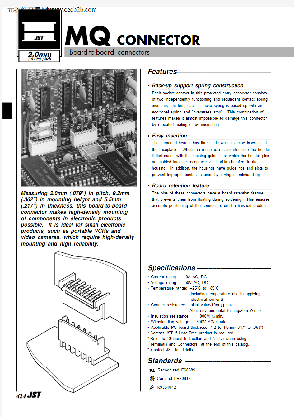
? Back-up support spring construction
Each socket contact in this protected entry connector consists of two independently functioning and redundant contact spring members. In turn, each of these spring is based up with an additional spring and "overstress stop". This combination of features makes it almost impossible to damage this connector by repeated mating or by mismating.
? Easy insertion
The shrouded header has three side walls to ease insertion of the receptacle. When the receptacle is inserted into the header,it first mates with the housing guide after which the header pins are guided into the receptacle via lead-in chamfers in the housing. In addition, the housings have guide ribs and slots to prevent improper contact caused by prying or mishandling.
? Board retention feature
The pins of these connectors have a board retention feature that prevents them from floating during soldering. This ensures accurate positioning of the connectors on the finished product.
Specifications –––––––––––––––––––
? Current rating: 1.0A AC, DC ? Voltage rating:250V AC, DC
? Temperature range:-25?C to +85?C
(including temperature rise in applying electrical current)
? Contact resistance:Initial value/10m ?max.
After environmental testing/20m ?max.
? Insulation resistance:1,000M ?min. ? Withstanding voltage:800V AC/minute
? Applicable PC board thickness: 1.2 to 1.6mm(.047" to .063")*Contact JST if Lead-Free product is required.
*Refer to "General Instruction and Notice when using Terminals and Connectors" at the end of this catalog.* Contact JST for details.
Standards ––––––––––––––––––––––0Recognized E60389
1Certified LR208122
R9351042
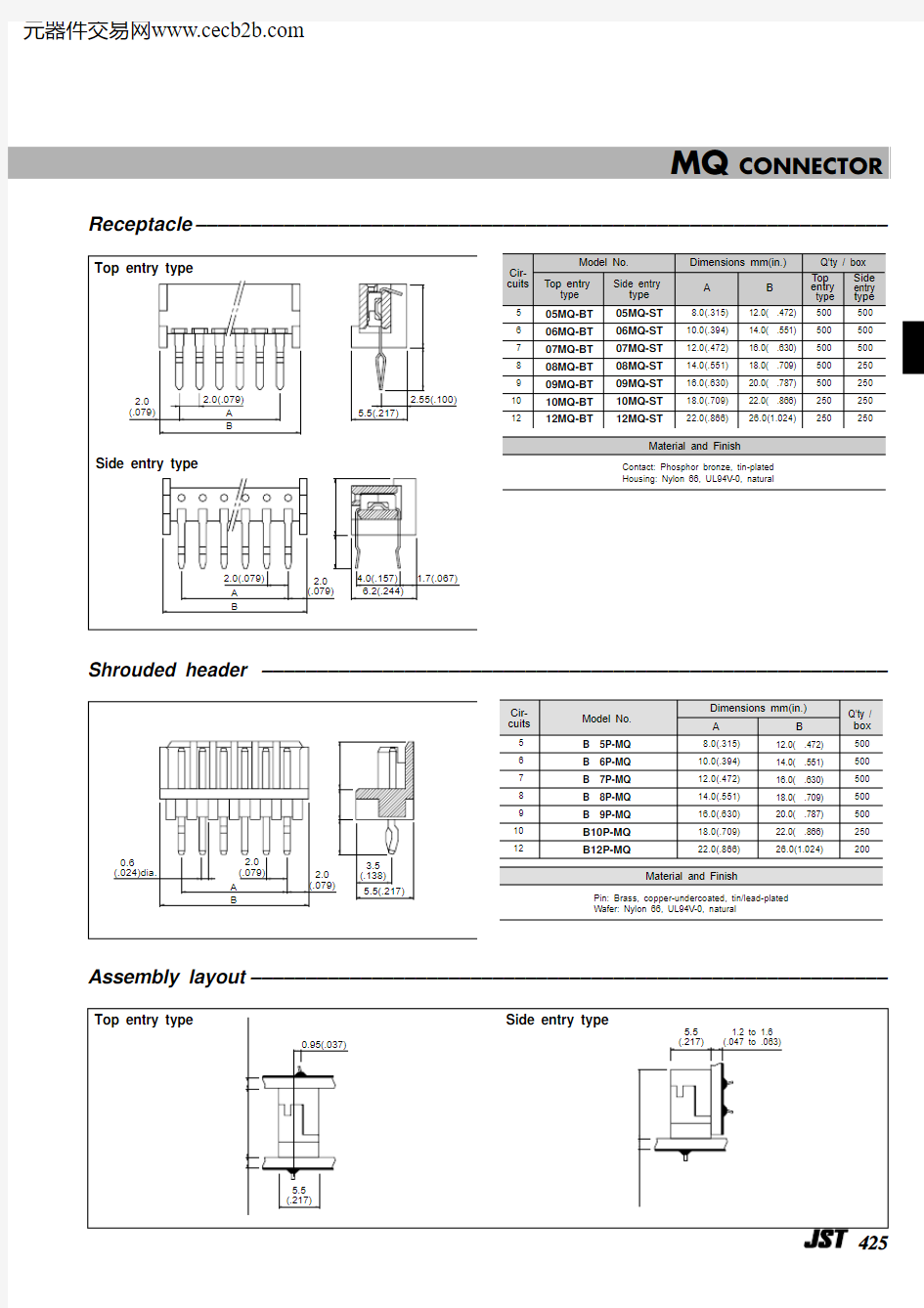
Receptacle–––––––––––––––––––––––––––––––––––––––––––––––––––––––––––––––Shrouded header –––––––––––––––––––––––––––––––––––––––––––––––––––––––––Assembly layout––––––––––––––––––––––––––––––––––––––––––––––––––––––––––
MQ CONNECTOR
MQ CONNECTOR
Low insertion force type Receptacle –––––––––––––––––––––––––––––––––––––––––
Low insertion force type Shrouded header ––––––––––––––––––––––––––––––––––––
Low insertion force type Assembly layout–––––––––––––––––––––––––––––––––––––
MQ CONNECTOR PC board layout (viewed from soldering side) –––––––––––––––––––––––––––––––––––––
1. The PC board layout of the header is identical to that of the top entry receptacle.
2. Tolerances are non-cumulative: ±0.05mm(±.002" ) for all centers.
3. Hole dimensions differ according to the kind of PC board and piercing method. The dimensions above should serve as a guideline.
Contact JST for details.
427