DIZ232-1
ALSPA C80-HPCi
Modular High-Performance Control, Monitoring and Computing System
Rev.: 00 / 09.02
473 (LUE) EN
Page 1/4
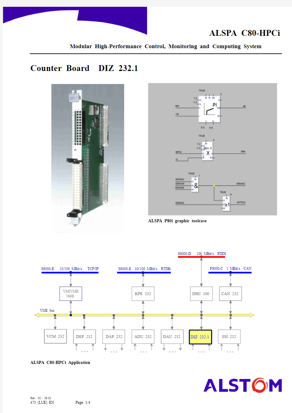
Counter Board DIZ 232.1
ALSPA P80i graphic toolcase
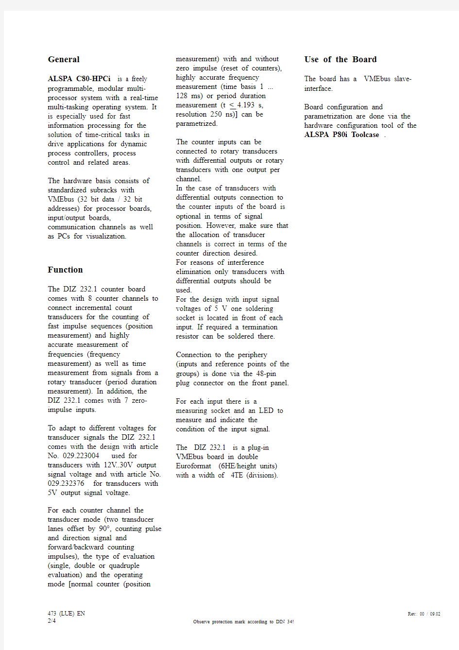
ALSPA C80-HPCi Application
473 (LUE) EN Rev.: 00 / 09.02
2/4
Observe protection mark according to DIN 34!
General
ALSPA C80-HPCi is a freely programmable, modular multi-processor system with a real-time multi-tasking operating system. It is especially used for fast
information processing for the solution of time-critical tasks in drive applications for dynamic process controllers, process control and related areas.The hardware basis consists of standardized subracks with VMEbus (32 bit data / 32 bit addresses) for processor boards,input/output boards,
communication channels as well as PCs for visualization.
Function
The DIZ 232.1 counter board comes with 8 counter channels to connect incremental count transducers for the counting of fast impulse sequences (position measurement) and highly accurate measurement of frequencies (frequency
measurement) as well as time measurement from signals from a rotary transducer (period duration measurement). In addition, the DIZ 232.1 comes with 7 zero-impulse inputs.
To adapt to different voltages for transducer signals the DIZ 232.1comes with the design with article No. 029.223004 used for
transducers with 12V..30V output signal voltage and with article No.029.232376 for transducers with 5V output signal voltage.
For each counter channel the transducer mode (two transducer lanes offset by 90°, counting pulse and direction signal and forward/backward counting impulses), the type of evaluation (single, double or quadruple evaluation) and the operating mode [normal counter (position
measurement) with and without zero impulse (reset of counters),highly accurate frequency measurement (time basis 1 ...128 ms) or period duration measurement (t < 4.193 s,resolution 250 ns)] can be parametrized.
The counter inputs can be
connected to rotary transducers with differential outputs or rotary transducers with one output per channel.
In the case of transducers with differential outputs connection to the counter inputs of the board is optional in terms of signal
position. However, make sure that the allocation of transducer
channels is correct in terms of the counter direction desired.For reasons of interference
elimination only transducers with differential outputs should be used.
For the design with input signal voltages of 5 V one soldering socket is located in front of each input. If required a termination resistor can be soldered there.Connection to the periphery
(inputs and reference points of the groups) is done via the 48-pin plug connector on the front panel.For each input there is a
measuring socket and an LED to measure and indicate the condition of the input signal.The DIZ 232.1 is a plug-in VMEbus board in double
Euroformat (6HE/height units)with a width of 4TE (divisions).
Use of the Board
The board has a VMEbus slave-interface.
Board configuration and
parametrization are done via the hardware configuration tool of the ALSPA P80i Toolcase .
Rev.: 00 / 09.02
473 (LUE) EN
Observe protection mark according to DIN 34!
3/4
Technical Specifications
Inputs (12V..30V signal voltage)8 counter inputs,
Article No. 029.223004
7 zero-impulse inputs; potential-free Ue1=12 V ... 30 V Ie1= 6 mA ± 30 %Ue0=0 V ... 5 V fe <500 kHz
t
=
0,2 μs (signal delay for zero-impulse inputs)Inputs (5V signal voltage)8 counter inputs,
Article No. 029.232376
7 zero-impulse inputs; potential-free RS422
Ue1= 5 V
Ie1= 6 mA ± 30 %fe < 2 MHz
t
=0,1 μs (signal delay for zero-impulse inputs)
Supply VMEbus
UB5
=+5 V, ±3%I
<
300 mA
Ambient Conditions
Ambient temperature 0° to + 55° C Storage temperature - 40° C to +85° C Humidity Class F (DIN 40040)
Mechanical Design
Size
6HE with 4TE (6 height units with 4 divisions)Dimensions approx. 233.4 mm x 160 mm x 20.5 mm (h × d × w)
Reorder Data
Type
DIZ 232.1
Article No.:029.223004 (Input voltage 12V...30V)Article No.:
029.232376 (Input voltage 5V)Documentation No.:
447 (BG) EN (ALSTOM)Peripheral Connector Layout
Connection at plug (control loop)
Note:If the input voltages at the "+" counter inputs are more positive than those at the "-" counter inputs,the counters count forward.
If the input voltages at the "+" zero-impulse inputs are more positive than the input voltages at the "-" zero-impulse inputs, zero-impulses are assumed as 1-signal.
473 (LUE) EN Rev.: 00 / 09.02 4/4Observe protection mark according to DIN 34!