11_System_Generator_Integration_Lab
System Generator Integration Lab
System Generator Integration Lab
Introduction
In this lab you will explore how a block generated by the AccelDSP? synthesis tool can be
incorporated into a larger System Generator design. This overall design has been done in System
Generator, but the QRD-RLS (QR Decomposition Recursive Least Squares) block is not
complete. You will complete this block in the MATLAB? software and then incorporate the block
into the System Generator design.
Objectives
After completing this lab, you will be able to:
Generate a System Generator model from an AccelDSP synthesis tool design
Import a block generated by the AccelDSP synthesis tool into a larger System Generator
design
Simulate the larger design using the Simulink? software
Algorithm Overview
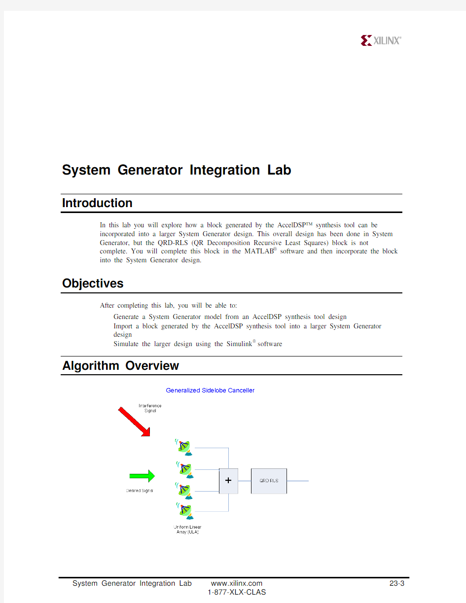
The algorithm is a generalized sidelobe canceller. This algorithm is designed to pass a signal
coming from the left (green arrow) because the beamformer is “steered broadside.” The desired
signal arrives at all four antennas at the same time. The algorithm attenuates signals that reach the
four antennas at different times. These signals came from other angles (the red arrow in this
simulation).
Procedure
n Navigate to the training_labs/11_GenerateSystemGenerator/AccelDSP folder. Invoke the AccelDSP synthesis tool and load the project file “gsc.acc”
o Perform the Verify Floating Point step. This will sub-invoke the MATLAB software and perform a floating-point simulation on the design. You will see the following three plots
appear. The first shows the signal arriving at each of the four antennas. Each antenna sees a
slightly different version of the signals. Figure 2 shows the time and frequency domain
representation of the signal for one antenna. Figure 3 shows the time and frequency domain
representation of the output
p As shown below, set the Flow to System Generator, and then perform the steps in the flow through Verify RTL
q The next button in the flow is Generate System Generator. Click this button to generate the System Generator model
r The AccelDSP synthesis tool now asks you to select the target Simulink library. The newly generated block will be added to this library. Click New to create a new library. Call the
library AccelDSP and place it in the AccelDSP/AccelWork directory. The path to this new library will automatically be added to the MATLAB software search path
s As shown below, select the new AccelDSP library to add the block into. Click OK. The path to this block will automatically be added to the MATLAB software search path
t Invoke the MATLAB software and change the working directory to the SystemGenerator folder. Double-click the adapt_4chan_beam_v1.mdl file to launch the Simulink software. A diagram will appear with a missing block that you will fill in with the AccelDSP QRD-RLS block. Double-click the broadside beamformer block to show that this sub-system is, in fact, comprised of Xilinx System Generator blocks
u Launch the Simulink Library Browser and expand the library AccelDSP
v Connect the qrd_rls block on the diagram as shown below:
w Run the simulation. You should observe the following plots that insure the GSC is functioning correctly. Notice the attenuation of the second spike at 2.2 mHz
Conclusion
The AccelDSP synthesis tool “Generate System Generator” command provides a powerful
automated way to create custom blocks for System Generator using floating-point MATLAB
software. These blocks can be used with blocks from the Xilinx Blockset to create large designs.