1999-Axial-Rotor-Oscillations-in-Cryogenic-Fluid-Machinery
Proceedings of the
3rd
ASME/JSME Joint Fluids Engineering Conference 1999 ASME Fluids Engineering Division Summer Meeting
July 18-23 1999, San Francisco, California
FEDSM99 S-291
AXIAL ROTOR OSCILLATIONS IN CRYOGENIC FLUID MACHINERY
CAHIT A. EVRENSEL Associate Professor College of Engineering
University of Nevada, Reno, USA
HANS E. KIMMEL
Ebara International Corporation Research and Development Sparks, Nevada U.S.A .
DAVID M. CULLEN
Ebara International Corporation
European Office Epsom, Surrey, U.K.
ABSTRACT
The design of the majority of rotating machinery ensures
the thrust load on the rotor is positive in one direction. Thrust
bearings accommodate such axial force thereby locating the
rotor in a fixed predetermined axial position.
Submerged cryogenic rotating machinery: pumps, as well
as hydraulic turbines, utilize a unique thrust equalizing
mechanism. This device ensures thrust equalization through
dynamic positioning. The mechanism is self-adjusting such that
an equilibrium position depends on the various forces, which
act on the rotor in axial direction.
These forces are generated due to the electromagnetic field
aligning the rotor at its magnetic center, coupling of the axial
and radial modes of vibration, interaction between the axial
motion of the pump impeller-shaft assembly and the flow
through the thrust balancing mechanism.
Measurements on pumps have shown the rotor oscillates
around a stable axial equilibrium position. Because this occurs
during rotation of the pump at design speed these oscillations
may influence ball bearing stiffness, load and life expectancy.
This paper presents the first series of measurements and
indicates further investigations are required.
INTRODUCTION
Liquefied gases with very low boiling temperatures are
called cryogenic fluids and are increasingly utilized in
industrial and scientific applications.
Liquid air, nitrogen, ammonia, hydrogen, and oxygen, and
liquefied hydrocarbon gases such as natural gas, methane, and
ethane constitute the major share of cryogenic fluids. These
fluids have to be transported and stored in a similar, if more
sophisticated, manner as any other conventional liquid.
To solve the transportation problem, a variety of
centrifugal pumps for cryogenic liquids have been developed in
the past 25 years. Today, the predominant pump design in
cryogenics is the multi-stage centrifugal pump with submerged
electric motor and with a thrust balancing device fitted
successfully to over 1500 operating machines (Weisser, 1994).
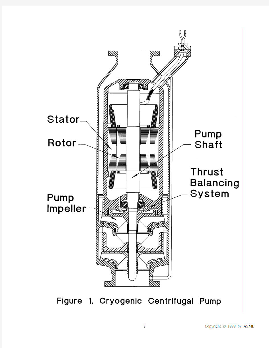
Figure 1 demonstrates the cross section of a typical cryogenic centrifugal pump with two stages. The two pump impellers and the rotor of the submerged electric induction motor are mounted together on the rotating pump shaft. The thrust balancing system is mounted on the back shroud of the high-pressure stage impeller. Figure 2 shows the thrust balancing mechanism for the case of zero thrust, and Figure 3 for the case of unbalanced axial thrust. These pumps are equipped with ball bearings, and are submerged, lubricated, and cooled by the cryogenic fluid. It is therefore important to balance the axial thrust properly in a controlled manner to increase the life of the cryogenic bearings. In addition to centrifugal pumps, power recovery from the expansion of high-pressure cryogenic liquids has significantly advanced in recent years, using hydraulic reaction turbines for the thermodynamic expansion of liquefied gases (Cengel and Kimmel, 1997). Consistent with the early experience on cryogenic centrifugal pumps, the prevailing design for cryogenic turbines is that of a multi-stage reaction turbine with submerged electric generator and thrust balancing device (Kimmel, 1998). Both centrifugal pumps and reaction turbines operated without thrust balancing devices generate a high axial hydraulic thrust, which can reach several kilo-Newtons on multistage turbines, resulting in heavy loads with significantly reduced hydraulic efficiency and bearing life (Weisser, 1998). It is therefore an important requirement in cryogenic fluid machinery to furnish the centrifugal pumps and reaction turbines with a thrust-balancing device (Weisser, 1997). THRUST BALANCING MECHANISM
Common thrust balancing devices use the hydraulic pressure of the fluid to equalize the axial thrust. It is necessary to design the pump or turbine in such a way the rotor assembly is allowed to have small axial movements to attain the thrust balancing effect. The prevailing design for a thrust balancing mechanism (Heath and Kimmel, 1998) in cryogenic pumps and turbines is shown in the following figures.
The thrust balancing mechanism is a two-orifice system with one fixed orifice and one variable orifice. The left side of Figure 3 indicates the upper position of the rotor assembly with the variable orifice closed, thus generating down thrust, and the right side shows the lower position with the variable orifice open, therefore generating up thrust. The density of the dots indicates a higher or lower pressure distribution.
Between these two limiting positions is one position of the rotor assembly where the total sum of all thrust forces is equal to zero, allowing the assembly in the steady case of operation to remain in a stable balanced position.
The effect of the self-adjusting thrust balancing mechanism can be compared to a spring with a non-linear spring characteristic, and will perform equally well over a wide range of differential heads, flow rates and variations in rotational speed. Such mechanism has been proven in numerous applications over many years.
The design of the above-described thrust balancing mechanism is completely applicable to hydraulic reaction turbines (Kimmel, 1998) and operates in the same manner as for centrifugal pumps.
AXIAL OSCILLATIONS
The modeling of the thrust balancing mechanism as a spring with a non-linear characteristic can be extended to include the reaction forces of the ball bearings. The combined arrangement of this modeled spring together with the mass of the rotor assembly and the axial rotor movement forms an axially oscillating mechanical system with non-linear damping.
Any fluctuation in the distribution of the fluid pressure or in the electromagnetic field of the motor results in an excitation of axial rotor oscillations. Additional exciting forces for axial oscillations are rotor dynamic vibrations (Habets and Kimmel, 1999)and vibrations in the housing.
The systems of fluid and flexible solid structures have natural frequencies and modes of both media. These modes are modified due to the coupling between two media (Evrensel and Kalnins, 1998).
The numerical results of investigations on fluid-structure interaction forces (Childs, 1991) indicate that perturbed impeller shroud forces resulting from the fluid-structure interaction may become important for pumps with very low axial natural frequencies in comparison to the running speed. Due to similar coupling of the axial motion of the pump impeller-shaft assembly and the flow through the thrust balancing mechanism fluid-structure interaction forces may influence the axial vibration modes.
Gyroscopic effects and coupling with the centrifugal and flexural modes of vibration may cause force and vibration in the axial direction (Genta and Tonoli, 1996).
While cross-coupling stiffness coefficients are negligible with simple radial or axial preloads, under the combined radial plus axial preload condition, the cross-coupling stiffness coefficient between the axial direction and the direction of the radial reload becomes significant (Royston and Basdogan, 1998)
These theoretically predicted axial rotor oscillations have remained undetected in previous cryogenic pump or turbine experiments. To verify the predicted oscillations, a thrust balanced eight stage cryogenic pump for liquefied natural gas was equipped with a cryogenic proximity probe, based on the eddy current principle, to measure the distance between rotor assembly and pump housing with a sample rate of 2 kHz.
The extensive tests successfully verified the predicted axial rotor oscillations, and a typical measured axial oscillation is recorded in the graph of Figure 4.
Figure 4 (upper section) shows the measured axial rotor displacement in millimeters relative to the pump housing during a time interval of 0.5 seconds, and for a quasi steady flow rate and discharge pressure of 87. 670 m3/h and 5.85 MPa. This trace has been recorded while the pump was operating at its design point at a nominal speed of 3600 rpm.
TEST EVALUATION
Using the Marquardt-Levenberg nonlinear least squares algorithm (Marquardt, 1963) to analyze the recorded oscillations with the following specified model for the displacement y,
y = ∑[ a n sin (2πf n+ Φn) ];
with n = 1,2,3,4
the listed parameters for the amplitudes a n , frequencies f n and phases Φn allow the specified model to converge to a local minimum of the least squares error sum.
a1 = 0.006400 mm a2 = 0.002977 mm
a3 = 0.000608 mm a4 = 0.000651 mm
f1 = 60.000 Hz f2 = 120.000 Hz
f3 = 180.000 Hz f4 = 1.630 Hz
Φ1 = 0.4997πΦ2 = 0.4082π
Φ3 = 1.1990πΦ4 = 0.5098π
The algorithm identifies a 60 Hz oscillation with its second and third harmonics, and a low frequency oscillation of 1.63 Hz.
Figure 5 demonstrates the least squares fit oscillation with the displacement in millimeters, and its first and second derivative, the velocity in mm/s and the acceleration in mm/s2. The maximum velocity is in the range of 4.5 mm/s and the maximum acceleration is 2.4 m/s2 or 0.25g.
The 60 Hz oscillation with its second and third harmonic can be typically attributed to the electromagnetic centering forces of stator and rotor of the three-phase induction motor. The 1.63 Hz oscillation is caused by the relatively slow axial movement of the thrust balancing mechanism due to the slow reacting hydraulic balancing forces.
Figure 4 (lower section) shows the error, the difference between the measured oscillations (upper section) and the least
squares fit model (middle section). The error indicates additional oscillations with small amplitudes and higher frequencies, which could not be identified with the present test arrangement. The error includes also a random error of the proximity probe, which is in the range of a micron. CONCLUSION
The presented test results have verified the predicted axial rotor oscillations exist in cryogenic turbo machines with thrust balancing mechanism. The measured oscillations are complex multi frequency oscillations which are caused by the centering forces of the electric motor, the thrust balancing mechanism and other exciting forces, including housing and structural vibrations, which have to be investigated and identified in further tests (Cullen and Kimmel, 1999).
There are indications that rotordynamic vibrations (Habets and Kimmel, 1999) and axial oscillations influence each other through variations in ball bearing stiffness due to the time dependent axial load. It is assumed the axial oscillations have either a stabilizing or an exciting effect on the rotor vibrations. Theoretical investigations of the rotor dynamics with time dependent stiffness parameters have to be performed parallel to the tests to establish an acceptable model to predict this anomalous phenomena of axial rotor oscillations. These oscillations may effect ball bearing load and stiffness. Further tests with more detailed measurements are in preparation to provide more comprehensive information on axial rotor oscillations.
ACKNOWLEDGEMENT
The University of Nevada Reno, College of Engineering and Ebara International Corporation are indebted to the encouragement and assistance received from G.L.G.M. Habets of Shell International Oil Products BV, The Hague, The Netherlands, without whose advice and initiative the project objectives would not have been realized. REFERENCES
Cengel, Y.A. and Kimmel, H.E., 1997, “Power recovery through thermodynamic expansion of liquid methane”, Proceedings of the 59th American Power Conference, Illinois Institute of Technology, Chicago, Illinois.
Childs, D.W., 1991, “Fluid-structure interaction forces at pump- impeller-shroud surfaces for axial vibration analysis”, Journal of vibration and acoustics-transactions of ASME, V ol.113, pp.108-115. Cullen, D.M. and Kimmel, H.E., 1999, “Method and device to monitor vibration on thrust balanced pumps and turbines”, US Patent pending, January 21,1999; 60/116713.
Evrensel, C.A. and Kalnins, A., 1998, “Response of a compliant slab to viscous incompressible fluid flow”, Journal of Applied Mathematics, V ol.55, pp.660-666.
Genta, G. and Tonoli, A., 1996, “A harmonic finite element analysis of flexural, torsional and axial rotordynamic behavior of disks”, Journal of Sound and Vibration, V ol.196, pp.19-43. Habets, G.L.G.M. and Kimmel, H.E., 1999, “Development of a hydraulic turbine in liquefied natural gas”, IMechE Seventh European Congress on Fluid Machinery, The Hague, Netherlands.
Heath, J.C. and Kimmel, H.E., 1998, “Liquefied natural gas pump technology in ground transportation”, NGV 98, Proceedings of the International Conference and Exhibition for Natural Gas Vehicles, Cologne, Germany.
Kimmel, H.E., 1998, “Power generation using thrust balanced hydraulic turbines”, Proceedings of the 60th American Power Conference, Illinois Institute of Technology, Chicago, Illinois. Marquardt, D.W., 1963, “An algorithm for least squares estimation of nonlinear parameters”, Journal of the Society for Industrial and Applied Mathematics, pp.431-441.
Weisser, G.L., 1994, “Modern submersible pumps for cryogenic liquids”, World Pumps, Elsevier Science Ltd., U.K.
Weisser, G.L., 1997, “Hydraulic turbine power generator incorporating axial thrust equalization means”, US-Patent, 5 659 205, Aug.19, 1997
Weisser, G.L., 1998, “Electric motor pump with magnetic coupling and thrust balancing means”, US-Patent pending, 09/200,409; Nov.11, 1998