DEFORM3D_v10.2_MO3_lab

MULTIPLE OPERATIONS LAB 1 1.1.Creating a New Problem 1 1.2.Creating a Furnace Heating Simulation 3 1.3.Adding a Heat Transfer Operation 9 1.4.Adding a Deformation Operation 12 1.5.Running the Simulation 23
1.6.Postprocessing the Simulation 24
Multiple Operations Lab
1.1. Creating a New Problem
On a UNIX machine, type DEF_MO3 to open DEFORM?-3D Multiple Operations. On
a Windows machine, go to the button and select DEFORM?-3D Multiple
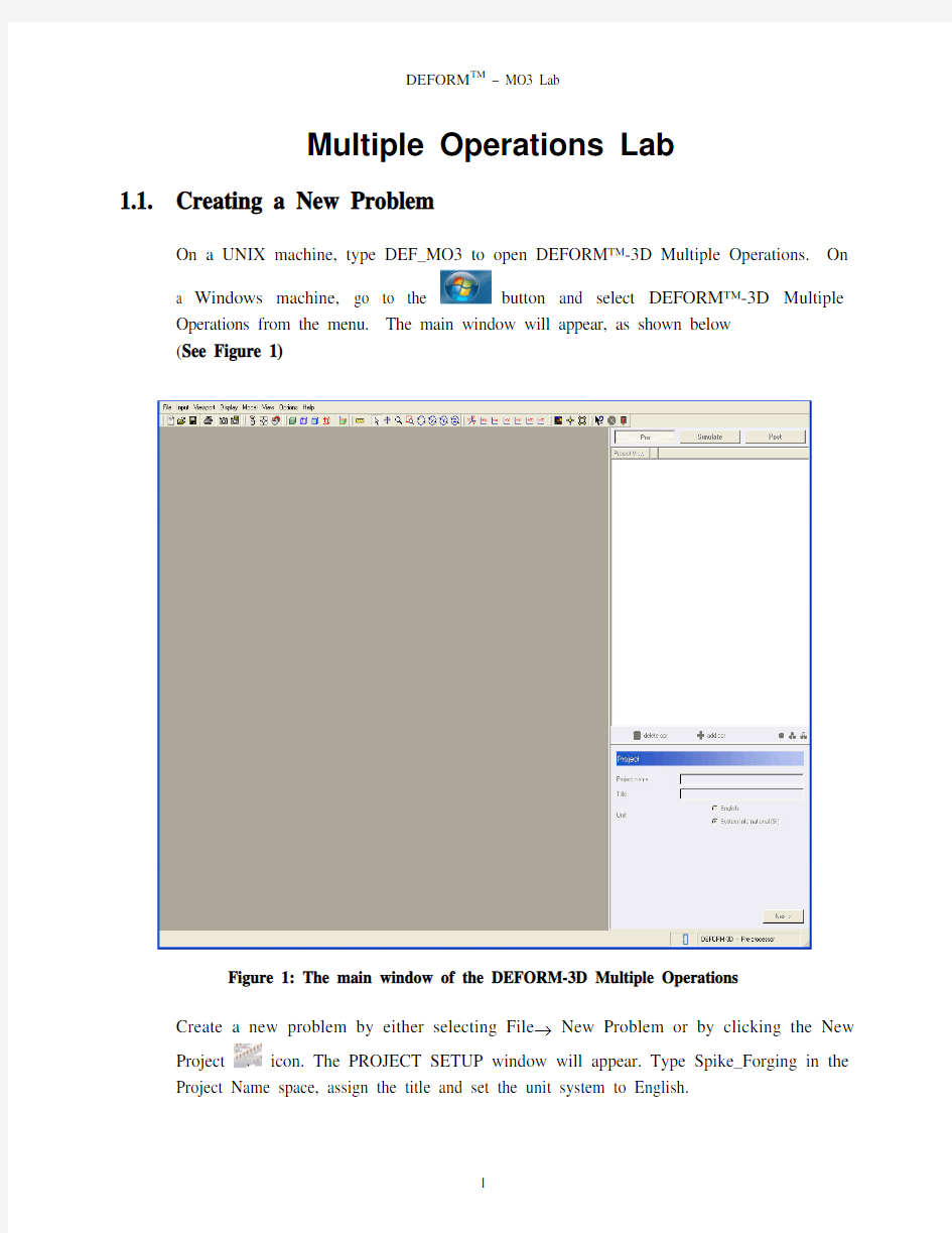
Operations from the menu. The main window will appear, as shown below
(See Figure 1)
Figure 1: The main window of the DEFORM-3D Multiple Operations
Create a new problem by either selecting File → New Problem or by clicking the New
Project icon. The PROJECT SETUP window will appear. Type Spike_Forging in the Project Name space, assign the title and set the unit system to English.
Layout of DEFORM-MO3
The layout of the interface can be seen in the figure below. The screen is distributed into four discrete sections. The display window is where the objects for the current operation can be viewed. The project list window is where the list of settings currently editable. Based on the selection in the project list window, certain values can be edited in the setting modification window. As information is provided to the interface, information will be printed in the project record window such as saved steps (See Figure 2)
Figure 2: The layout of the multiple operations interface
The process setting window, as seen below (See Figure 3), should appear on the screen. This window allows the user to insert various operations into the process list.
Figure 3: The process setting dialog
1.2. Creating a Furnace Heating Simulation
Drag the Heat Furnace icon into the project list window. This will then add a furnace heating operation to the beginning of list. To edit this operation, please click the Open opr button as seen below (See Figure 4).
Figure 4: Adding and opening operations
Click to accept the default name of this operation. The number of objects
need not be edited at this time so click the button (See Figure 5).
The values in the setting modification window are values for the workpiece. Accept the
defaults and click(See Figure 6).
Figure 6: Object properties description window
Click the Import geometry link and select the file Spike_Billet.STL in the LABS
subdirectory where your version of DEFORM-3D is installed and then click. Go to advanced properties in workpiece object page. Activate Volume compensation with “Active in FEM” Click “OK”. In the meshing window, set the number of elements to
4000, click Generate mesh and click(See Figure 7). Please note that this mesh is generally coarser than recommended for many cases and it is set low to expedite the simulation times for this lab.
Figure 7: Meshing options window
At this window, the user is required to define the material properties for the workpiece.
This can be done a variety of ways but in this lab, the material library will be used.
Please click Import material from library and select AISI-1015 [70-2000F (20-1100C)] under steel and click (See Figure 8).
Figure 8: Material selection
In this window we need to define the boundary condition, click on define BCC and select the heat exchange with environment. Select all the surfaces except symmetry surfaces for heat exchange with environment and then click on to add (See Figure 9). Select symmetry planes
and select the symmetry surfaces. Close the BCC window and click
(See Figure 10).
Figure 9: BCC Options for Heat Furnace option
Figure 10: Selecting symmetry planes
At this time, positioning would not be considered. Since this is a furnace heating operation, there are no dies and positioning does not have to be considered at this point.
Please click.
In this screen, the process parameters for the furnace heating should be defined. These parameters are the time in the furnace, the temperature of the furnace and the convection
coefficient inside the furnace. Please take the defaults for all three and click
(See Figure 11).
Figure 11: Process parameters options for Heat Furnace option
In this window, the number of simulation steps and the step increment to save is defined. Enter the number of steps to 1000 and Step increment 25, with constant time increment
3.6 sec per step and click(See Figure 12).
Figure 12: Simulation controls for Heat Furnace option
At this time, please click Check data the database and Generate database. Click the
and close the current operation(See Figure 13).User can read in any additional operation specific data that could not be defined using this general MO3 system using the option ‘Append user defined keyword file’. This data gets included before database generation.
Figure 13: DB generation at options
1.3. Adding a Heat Transfer Operation
At this stage, the furnace heating operation has been generated. At this time, subsequent operations can be defined before the furnace heating needs to be performed.
Click the button to open the Process Setting window. Drag the Heat Transfer icon into the Project View list. Click on the Heat-Transfer operation and Click the Open Opr button.
The first screen allows the user to name the current operation. Please keep the default name and click.
The current screen allows the user to define the number of objects. In the case of a heat transfer operation, only the workpiece is modeled. Please click.
Notice that the Read from DB checkbox is checked. This means that the result of the
furnace heating operation will be used for this operation. Please click(See Figure 14).
Figure 14: Window showing that db has been taken from last operation
Question: What does the "Read from DB" checkbox mean?
Answer: This tells the system not to define any information for this object. The data for the object should be obtained from the previous operation available from the database. In cases where a part is moving through a multiple operation progression, each operation should keep the workpiece from the previous operation.
The object does not need to be positioned at this time, so click. The process
condition window can be seen. Accept the default values and click (See Figure 15).
Figure 15: Process setting window for heat transfer operation
At this time the simulation controls window is seen. Accept the defaults and click
(See Figure 16).
Figure 16: Simulation controls for Heat Transfer option
In this window, no database should be generated so click the button.
Question: What does the "Append user defined keyword file" checkbox mean?
Answer: This tells the system to also read an optional keyword file when automatically setting up this operation. Defining this keyword file in outside the scope of this lab but it is important to note that this advanced feature allows special, previously defined options to be applied between simulations (See Figure 17).
Figure 17: Window showing “Append user defined keyword file" option
1.4. Adding a Deformation Operation
At this stage, two operations have been defined. The workpiece is ready to be forged.
Click the button to open the Process Setting window. Drag the Deformation icon into the Project View list. Click on the Deformation operation and Click the Open Opr button.
The first screen allows the user to name the current operation. Please keep the default
name and click(See Figure 18).
Set the number of objects to 3 and then click.
Figure 18: Adding the objects for simulation
Notice that the Read from DB checkbox is checked. This means that the result of the
transfer operation will be used for this operation. Please click
(See Figure 19).
Figure 19: Window showing that db has been taken from last operation
In this window we need to define the movement for the object, since object is going to be stationary there is no need to edit movement hence click .
At this time, the top die must be added to the simulation. This window defines the basic object information and also allows the user to import a keyword file. Please click
.
Question: What does the "Skip this object in this operation" checkbox mean? Answer: This tells the system to not apply any information for this object at this operation. Therefore when the simulation runs, this object will be empty of information until a later operation. (See Figure20).
Figure 20: Window showing “skip this object in this operation” option
At this point, the user can import the geometry for the top die. Click the Import geometry link and select the file Spike_TopDie1.STL in the LABS subdirectory where
your version of DEFORM-3D is installed and then click .
Generate mesh for the top die with 1500 elements and then click (See Figure21).
Figure 21: Meshing options window
Import material AISI-H13 for the top die from library and then click (See Figure 22)
Figure 22: Material selection window.
This screen allows the movement for the top die to be defined. Please define a velocity of 10 in/sec in the -Z direction by clicking Edit movement and set these values and then
click(See Figure 23).
Figure 23: Movement control settings
In this window we are going to define Boundary conditions for top die. Under boundary
conditions options select Heat exchange with environment and then select all the surfaces
except symmetry surfaces and then click to add. Close the BCC window and click
(See Figure 24).
Figure 24: BCC Options of top die for Deformation
At this time, the user can define basic information for the bottom die. Accept the defaults and click. Click the Import geometry link and select the file Spike_BottomDie.STL in the LABS subdirectory where your version of DEFORM-3D is installed and then click.
Generate mesh for the bottom die with default elements number and then click
Select AISI-H13, which is already imported as the material for bottom die and then click . Since the bottom die is stationary there is no need to edit the movement controls hence click. In this window we are going to define Boundary conditions for bottom die. Under boundary conditions options select Heat exchange with environment and then select all the surfaces except symmetry surfaces and then click
to add. Close the BCC window and click.
At this time, the three objects are seen as in Figure 25. Note that the top die needs to be positioned down into the workpiece and the bottom die needs to be positioned up into the workpiece. (See Figure 29 and Figure 30).The top die and bottom dies have been defined at this step and can be positioned by offset positioning. However, the workpiece is to be "Read from DB" and its position at this step is not certain so the positioning can only be scheduled. Click Add to invoke the object-positioning window. Set the top die to position by interference into the workpiece in the -Z direction and set the bottom die to position by interference into the workpiece in the +Z direction. After setting this,
click(See Figure 26).
Figure 25: Scheduled positioning of top die in deformation operation