HIF6A-032DA-1.27DSA中文资料
A116
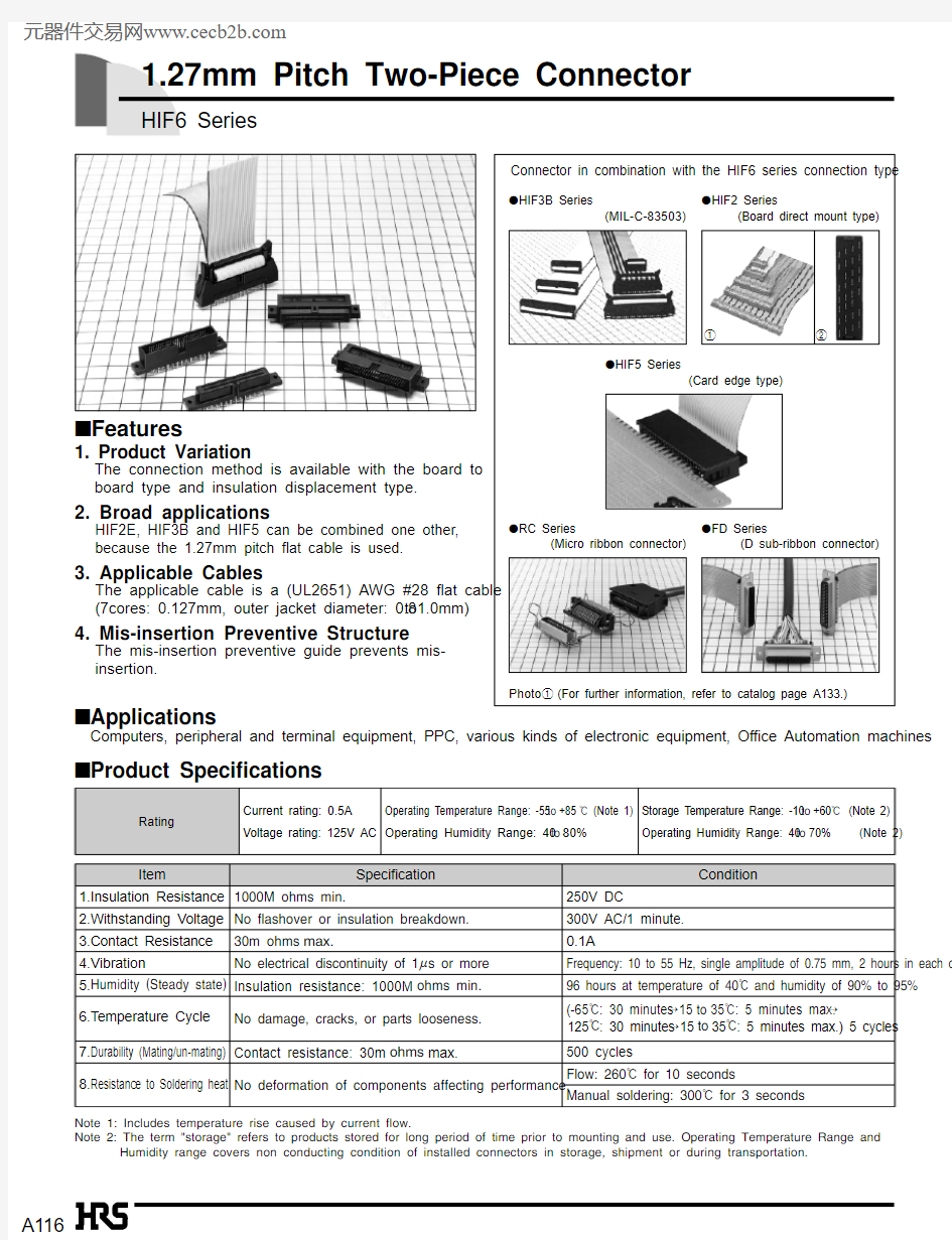
1.27mm Pitch Two-Piece Connector
HIF6 Series
s Features
1. Product Variation
The connection method is available with the board to
board type and insulation displacement type.
2. Broad applications
HIF2E, HIF3B and HIF5 can be combined one other,
because the 1.27mm pitch flat cable is used.
3. Applicable Cables
The applicable cable is a (UL2651) AWG #28 flat cable
(7cores: 0.127mm, outer jacket diameter: 0.8to1.0mm)
4. Mis-insertion Preventive Structure
The mis-insertion preventive guide prevents mis-
insertion.
Note 1: Includes temperature rise caused by current flow.
Note 2: The term "storage" refers to products stored for long period of time prior to mounting and use. Operating Temperature Range and Humidity range covers non conducting condition of installed connectors in storage, shipment or during transportation.
s Applications
Computers, peripheral and terminal equipment, PPC, various kinds of electronic equipment, Office Automation machines s Product Specifications
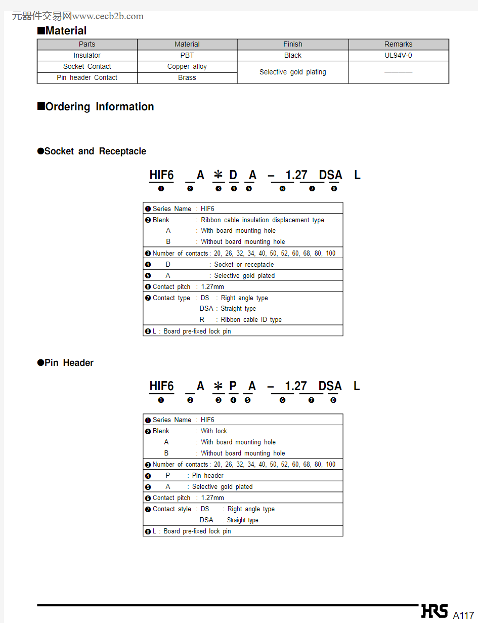
q HIF3B Series
(MIL-C-83503)
q HIF5 Series
(Card edge type)
q HIF2 Series
(Board direct mount type)
q RC Series
(Micro ribbon connector)
q FD Series
(D sub-ribbon connector)
Photo1(For further information, refer to catalog page A133.)
Connector in combination with the HIF6 series connection type
12
A117
s Material
A118B Function Chart
Pin Header Socket or Receptacle Side
Right Angle
Type with lock
Straight Type
with lock
Right Angle
Type with
mounting hole
Straight Type
with mounting
hole
Right Angle
Type without
mounting hole
Straight Type
without
mounting hole
Right Angle
Type with
mounting hole
Two pieces of 1.27mm
pitch cable used
HIF2B series
HIF3B series
HIF5 series
Ribbon cable FD
(D sub) connector
Ribbon cable RC30
(Micro ribbon) connector
Straight Type
with mounting
hole
Right Angle
Type without
mounting hole
Straight Type
without
mounting hole
a2.54 pitch connector
(MIL-C-83503)
A119
s
Cable ID Connector
Unit: mm
A120s
Pin Header Right Angle Type with lock
B PCB mounting pattern
q Indicate mark position.
Mating Side
Note : Size F indicates the state where the lock is open.
Unit: mm
n =
Number of Contacts
2
Mating Side
A121
s Pin Header Straight Type with lock
Note : Size F indicates a state where the lock is open.
(20, 32, 40, 52, 60, 68, 80, 100 contacts)
(26, 34, 50 contacts)
(26, 34, 50 contacts)
q Indicate mark position.
Unit: mm
n =
Number of Contacts
2
B PCB mounting pattern
Unit: mm
A122B PCB mounting pattern
Unit: mm
n =
Number of Contacts
2 (20, 32, 40, 52, 60, 68, 80 contacts)
*Lock pin type is
also available.
B Application Pattern
(26, 34, 50 contacts)
Mating Side
Mating Side
s Receptacle Right Angle Type with Mounting hole
A123
B PCB mounting pattern
Unit: mm
n =
Number of Contacts
2
(20, 32, 40, 52, 60, 68, 80 contacts)
B Application Pattern
(26, 34, 50 contacts)
Mating Side
Mating Side
s Receptacle Right Angle Type Without Mounting hole
A124
Unit: mm
n =
Number of Contacts
2 (20, 32, 40, 52, 60, 68, 80, 100 contacts)
B Application Pattern
(26, 34, 50 contacts)
Guide Key Side
Guide Key Side
s Receptacle Straight Type with Mounting hole
(26, 34, 50 contacts)
(20, 32, 40, 52, 60, 68, 80, 100 contacts)
B PCB mounting pattern
A125
Unit: mm
n =
Number of Contacts
2
Guide Key Side
s Receptacle Straight Type without Mounting hole
(20, 32, 40, 52, 60, 68, 80, 100 contacts)
B Application Pattern
(26, 34, 50 contacts)
(26, 34, 50 contacts)
(20, 32, 40, 52, 60, 68, 80, 100 contacts)
B PCB mounting pattern
A126s
Pin Header Right Angle Type with Mounting hole
Unit: mm
n =
Number of Contacts
2 (20, 32, 40, 52, 60, 68, 80, 100 contacts)
B
Application Pattern
(26, 34, 50 contacts)
πLock pin type is
also available.
Mating Side
Mating Side
B PCB mounting pattern
A127
Unit: mm
n =
Number of Contacts
2
(20, 32, 40, 52, 60, 68, 80, 100 contacts)
B
Application Pattern
(26, 34, 50 contacts)
Mating Side
Mating Side
s Pin Header Right Angle Type Without Mounting hole
B PCB mounting pattern
A128
Unit: mm
n =
Number of Contacts
2 (20, 32, 40, 52, 60, 68, 80, 100 contacts)
B Application Pattern
(26, 34, 50 contacts)
Guide Key Side
Guide Key Side
*Lock pin type is
also available.
(26, 34, 50 contacts)
(20, 32, 40, 52, 60, 68, 80, 100 contacts)
B PCB mounting pattern
s Pin Header Straight Type with Mounting hole
A129
Guide Key Side
Guide Key Side
Unit: mm
n =
Number of Contacts
2
(20, 32, 40, 52, 60, 68, 80, 100 contacts)
B Application Pattern
(26, 34, 50 contacts)
(20, 32, 40, 52, 60, 68, 80, 100 contacts)
(26, 34, 50 contacts)
B PCB mounting pattern
s Pin Header Straight Type Without Mounting hole
A130B Connection Circuit(20, 32, 40, 52, 60, 68, 80, 100 contacts)
A1an
A2an 1
An a1
·
·
·
·
·
·
·
·
·
·
·
·
·
·
·
·
·
·
·
·
·
·
·
·
B1bn
B2bn 1
Bn b1
Connection of Cable 1Connection of Cable 2
Type A, B
Connection of Cable 1
A1b1
A2b2
An bn
Connection of Cable 2
B1a1
B2a2
Bn an
·
·
·
·
·
·
·
·
·
·
·
·
·
·
·
·
·
·
·
·
·
·
·
·
Type A, A
n =
Number of Contacts
2
A131
B Connection Circuit
(26, 40, 50 contacts)
A
1an A 2
an 1
An
a 1······
······
······
······
B 1bn B 2
bn 1
Bn
b 1
Connection of Cable 1Connection of Cable 2Type A, B
Connection of Cable 1A 1b 1A 2
b 2
An bn Connection of Cable 2B 1a 1B 2
a 2
Bn an
······
······
······
······
Type A, A
n =
Number of Contacts
2
A132B Connection Jig
q Guide Plate
HIF 6 - GPA
CL550 - 0165 - 8
q Hi-Flex Connection Press
q Cable Cutter
HIF6 Cable Cutter-FC601
CL550 - 0166 - 0
q Instruction Manual for HIF6 Connection Service Method
14 Pages
Hi-Flex Connection Press HHP502
CL550 - 0082 - 2
A133
s
HIF6 Series: Connection Type Coupled Connector HIF3B Series (MIL-C-83503)
q Compliant with the MIL standard
q The VA idea is reflected on both pin header and socket.q Products with pull-out tab are available.
q Countermeasures are taken against noises in combination with the applicable cover case.q The type aligned in single-row, low profile type, is available for pin header locking system, in addition to standard products.
Number of contacts: 6, 10, 14, 16, 20, 26, 30, 34, 40, 50, 60, 64
HIF2 Series (Board direct mount type)
12-row parallel type (HIF2E)
Number of contacts: 10, 14, 16, 20, 26, 30, 34, 40, 50, 602.54mm grid alignment facilitates to the design pattern.24-row staggered type (HIF2C)
Number of contacts: 10, 14, 16, 20, 26, 30, 34, 40, 50, 60
Mounting height is 4.9mm low profile type.
HIF5 Series (Card edge ribbon type)
q Three types of full hole, semi-hole and no mount area are provided for the unit mount area.q Connectors are connected in the bus line system.q Cables can be returned within the connector mold width.
Number of contacts: 20, 26, 34, 40, 50, 60
RC Series (Micro ribbon connector)
q Since the cable insulation displacement area is standard pitch 1.27mm, the standard ribbon cable can be easily utilized.
q Countermeasures are taken against noises in combination with the cover case. q Cover case is light weight and compact.
q Straight and right angle types are installed on the dip side.
Number of contacts: 14, 24, 36, 50
FD Series (D sub-ribbon connector)
q The standard pitch 1.27mm ribbon cable can be insulated and displaced by replacing a jig, in addition to the same pitch 1.38mm as for the D sub connector.
q The space saving type allows to reduce the thickness on the connection side according to set miniaturization.
q Connectors can be installed from both front and rear sides of the chassis or panel.Number of contacts: 9, 15, 25, 37
1
2