A real time hand gesture recognition system using motion history image
A Real Time Hand Gesture Recognition System Using Motion History Image
Chen-Chiung Hsieh and Dung-Hua Liou Dept. of Computer Sci H nce and Engineering,
Tatung University
Taipe L, Taiwan
cchsieh@https://www.360docs.net/doc/2518172315.html,.tw
David Lee
Reallusion Inc.
2F, No. 126, Lane 235, Pao-Chiao Rd. Hsintien, Taipei County 231, Taiwan davidlee@https://www.360docs.net/doc/2518172315.html,
Abstract—Hand gesture recognition based man-machine interface is being developed vigorously in recent years. Due to the effect of lighting and complex background, most visual hand gesture recognition systems work only under restricted environment. An adaptive skin color model based on face detection is utilized to detect skin color regions like hands. To classify the dynamic hand gestures, we developed a simple and fast motion history image based method. Four groups of haar-like directional patterns were trained for the up, down, left, and right hand gestures classifiers. Together with fist hand and waving hand gestures, there were totally six hand gestures defined. In general, it is suitable to control most home appliances. Five persons doing 250 hand gestures at near, medium, and far distances in front of the web camera were tested. Experimental results show that the accuracy is 94.1% in average and the processing time is 3.81 ms per frame. These demonstrated the feasibility of the proposed system.
Keywords-hand gesture recognition; adaptive skin color model; motion detection; motion history image.
I.I NTRODUCTION
In recent years, computer vision based hand gestures recognition as input for man-machine interface is being developed vigorously. The most advantage of these techniques is that user can control devices without touching anything such as panel, keyboard, mouse, or remote controller. User just needs to face the camera and raise his/her hands for operation control. Hand gestures recognition systems make people having high degree of freedom and intuitive feelings.
The objective of this paper is to develop a real time hand gesture recognition system based on adaptive skin color model and motion history image (MHI). By adaptive skin color model, the effects from lighting, environment, and camera can be greatly reduced, and the robustness of hand gesture recognition could be greatly improved. We defined six hand gestures which are natural and no training is required before using. By defining four groups of Haar-like patterns, we could distinguish the four directional hand gestures effectively by statistical method. In additional, fist hand and waving hand are detected by checking a region of interest besides face. Fist hand is detected by the other Haar-like feature and waving hand is detected by checking the amount of motion within that specified region.
This paper is organized as follows. Section 2 gives some related researches in hand gesture recognition. Section 3 presents the detail of our method which is divided into two parts, one is face based adaptive skin color model and the other is MHI based direction detection of moving hand. Section 4 describes the experimental results. Finally, we make conclusions and give future works in the last section.
II.R ELATED W ORKS
Various computer vision based man-machine interface researches were developed by using cameras of single lens [1], multi-lens [2], depth perception lens [3], or infra-red lens [4]. Different lens give different information. The more information utilized, the higher recognition accuracy would be. However, these cameras may require special installations and cost much for the information extraction. According to the survey given in [5], there are other different methodologies used for human gesture recognition ranging from principle component analysis [6], hidden Markov model [7], particular filtering [8], and finite state machine [9], to neural networks [10]. In the following, we will brief some researches in hand gesture recognition for device control and discuss the feasibilities of proposed hand gestures for operation.
Wu [11] developed a hand gesture recognition system for media player control. The system firstly separated the left-arm by background subtraction and detected the straight line by both Hough transform and Radon transform. The disadvantage of this method was the non-instinct of defined hand gestures. Lai [12] designed and implemented an interactive biped robot which could be controlled by hand gestures. The number of fingers and angles between fingers were used to classify nine types of static hand gestures. To overcome the effect of lighting, they utilized scroll bars to manually set the scope of skin color in YC b C r space. Tu [13] presented a face based hand gesture recognition system for human-computer interaction by a single camera. Hand region was assumed to appear by the side of face. Eleven static hand gestures were defined to control the computer. Back propagation neural network was utilized for hand gesture recognition. However, users need to remember the meaning of each hand gesture which may be confused due to similar shape.
Some systems have limitations that user sat in front of camera within a specified distance. Here, we try to relax these limitations. Firstly, we propose a face based adaptive skin color model for hand region segmentation. Secondly, the adopted dynamic and static hand gestures are simple and intuitive. At last, simple and fast Haar-like features are
defined to classify the directional dynamic hand gestures in MHI representations.
III. S YSTEM A RCHITECTURE
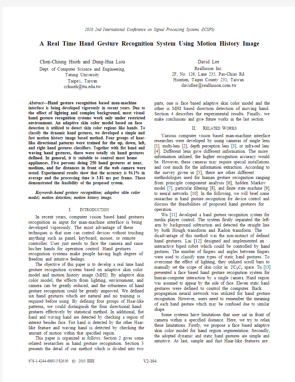
There are dynamic and static hand gestures defined as shown in Fig. 1. The direction of moving hand is used to classify the dynamic hand gestures in Fig. 1(a)-1(d) while motion detected or not by side of face is used to classify the two static hand gestures in Fig. 1(e) and 1(f).
Fig. 2 shows the flow chart of the proposed system in which face detection is one of the key components. Color independent face detection proposed by Viola and Jones [14] and extended by Lienhart and Maydt [15] is adopted. The characteristic of this method is the use of the black-white haar-like patterns to find eyes on face that is independent to the skin color of people. Thus, false alarms would happen at eyes-like patterns. In this paper, false alarms would be filtered out if the number of skin pixels within the detected face region is less than a given threshold. The system is divided into three major parts: digital zoom, adaptive skin color detection, and hand gesture recognition. Each part is
described in the following subsections.
A.
Digital Zoom
It is necessary to magnify the image area around the user for hand gesture recognition if user is distant from camera. Thus, user needs not to adjust his/her position. This step is to normalize the image size to 320×240 pixels for the initially
set camera resolutions may be different. If the detected face is smaller than the standard size of face, user could either adjust the face size manually by the equipped optical zoom capability of camera or using provided automatic zoom by bi-linear interpolation the region of interest (ROI) centered at the detected face. The ideal operating distance is about 60 centimeters in our hand gesture recognition system. If user is far away, he/she will appear smaller. By digital zoom, the user ROI could be enlarged and the recognition result would not be decreased.
B. Adaptive Skin Color Detection
Due to the general skin color scope [16] covers many skin-like colors, false positive or false negative are sometimes unacceptable. Hence, if we could construct an
adaptive skin color model, the misclassification rate would be greatly reduced. By exploiting skin color information from individual’s face to create the skin color model for each person will improve system robustness because of the reduced amount of color variations within a person’s face and hands [17].
The face-based adaptive skin color model proposed by Liou [18] is adopted here. Skin region of detected face could be obtained by eliminating eyes, nostrils, and mouth by gray level histogram analysis. Color distributions in normalized red, normalized green, and original red are assumed to be Gaussian distributions so that the means and standard deviations are calculated to build the adaptive skin color model. Afterward, we can use that skin color model to detect the other skin color regions for that person. From experimental results, our system could detect correct skin pixels even if it is in extremely bad lighting condition and even the face colors are not in normal skin chromaticity. C. Static Hand Gesture Recognition
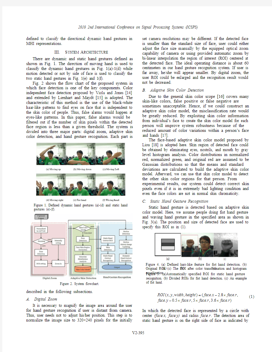
Static hand gesture is detected based on adaptive skin color model. Here, we assume people doing fist hand gesture and waving hand gesture in the specified area as shown in Fig. 3(a). The position and size of detected face are used to specify this ROI as in (1).
)
.6.3,.5,.5.0.,.8.2.(),,,(r face r face r face y face r face x face height width y x ROI u u u u
In which the detected face is represented by a circle with center (face.x, face.y) and radius face.r . The detection area of static hand gesture is on the right side of face as indicated by
Figure 2. System flowchart.
Figure 1. Defined dynamic hand gestures (a)-(d) and static hand gestures (e)-(f).
(a) (b) (c) Figure 3. (a)Automatically specified ROI for static hand gesture
recognition. (b) Divided ROIs for fist hand detection. (c) An example of fist hand.
(a) (b) (c)
Figure 4. (a) Defined harr-like feature for fist hand detection. (b) Original ROI. (c) The ROI after color transformation and histogram
equalization.
the red rectangle in Fig. 3(a). That set ROI is based on the habit of right-hand users and could be changed to the left side of face for left-hand users.
1) Fist Hand: The ROI for fist hand detection is further divided into four small areas as shown in Fig. 3(b). When user made a fist, the result of detected skin region would be as shown in Fig. 3(c). Hence, fist hand gesture could be recognized by checking these four small areas as in (2).
2413
1
Threshold R Threshold R
i i
t | E
In order to improve the identification accuracy, a simple harr-like feature as shown in Fig. 4(a) is used to check the fist hand as shown in Fig. 4(b). The ROI is firstly transformed from RGB to gray level and then the histogram is equalized as shown in Fig. 4(c) for recognition.
2) Waving Hand: Waving hand gesture recognition is based on motion detection and time sequence as shown in Fig. 5. By observing waving hand gesture in Fig. 5(a), two apparent phenomena would happen. Firstly, the motion as shown in Fig. 5(b) obtained by subtracting two continuous frames would be very obviously. Secondly, the motion would last for a period of time. Therefore, these two conditions are used to verify waving hand gesture. If the size of motion region in the preset ROI is large enough and lasts for a period of time, the waving hand gesture could be confirmed. The time period is set as three seconds in this paper.
D. Dynamic Hand Gesture Recognition
Dynamic hand gesture recognition was conducted by adopting motion information. Variations among frames could be accumulated in the motion history image. A simple direction detection method of moving hand based on motion history image is then proposed. Four groups of directional patterns are defined for measuring the quantities of directions. 1) Motion History Image: Fig. 6(a) and 6(b) show two continuous frames and Fig. 6(c) is the difference frame in which the resulting regions are the motion regions. To accumulate motion information in a single image, we get the motion history image as shown in Fig. 6(d). The benefit of motion history image is that it could preserve objects trajectories in one frame. Motion information are used to update the motion history image MHI as in (3), where DF is the difference frame and ? is set as 15. The values in MHI are 0-255.
D 11),(),(),(t t t y x DF y x MHI y x MHI
2)
Haar-like Patterns for Direction Detection: Four haar-like directional patterns as shown in Fig. 7 are
proposed to detect whether hands are moving up, down, left,
or right. For example, the motion history image as shown in Fig. 6(d) is used for classification. The counter of left would be increased lots of times because the patterns in Fig. 7(c) match with the motion history. That is, if the left element is brighter than the right element, the counter of left direction would be increased by one. Similarly, for each of the 30 left patterns, the counter will be increased if the above situation is satisfied.
The sum of all direction counters as in (4) is used to normalize the four direction counters as in (5)-(8). Table I shows the rules for classification and the corresponding thresholds. The dynamic hand gestures would be classified as the direction counter with the maximum value.
right left down up Count Count Count Count Sum
(a)
(b)
Figure 5. (a) Waving hand gesture. (b) Result of motion detection. (c) Threshold of waving hand elapsed time.
(a) (b)
(c) (d)
Figure 6. (a) Previous frame. (b) Current frame. (c) Difference
frame. (d) The resulting motion history image.
Sum Count UP up /)(2
Sum Count DOWN down /)(2
Sum Count LEFT left /)(2
Sum Count RIGHT right /)(2
IV. E XPERIMENTAL R ESULTS
The proposed hand gesture recognition system is tested to demonstrate its feasibility. The platform is Microsoft Windows XP on a PC with AMD Processor 5200+ and main memory 2G bytes. Logitech Portable Webcam C905 is used to capture images. The software development environment is Visual C++ 6.0 with image processing library OpenCV 1.1 installed.
After setting the digital zoom, adaptive skin color detection and hand gesture recognition could be activated by the check boxes. The result of hand gesture recognition was shown by the corresponding graphic arrow icon. The lower
right text box displayed the text description of hand gesture recognition for verification and log.
A. Hand Gesture Recognition
Fig. 8 shows the recognition results of a video containing 241 frames in which there are four directions of moving hand gestures. It starts from up, down, left, to down. These hand gestures could be classified by comparing the four direction counters, UP, DOWN, LEFT, and RIGHT that were calculated from the motion history image.
Five persons were requested to do the defined dynamic hand gestures at three different distances (<1m, 1m~1.5m, and 1.5m~2m) 50 times per type of dynamic hand gesture and 25 times per type of static hand gesture. Before testing, user could practice for one minute to prevent from wrong operation. The results were shown in Table II. Experimental results show that the recognition rates are 93.13% for dynamic hand gestures and 95.07% for static hand gestures. B. Processing Time Analysis
The objective of this paper is to propose a real-time convenient hand gesture recognition system as a man machine interface. The system is designed to work efficiently. The total processing time is 3.81 ms per frame if frame capture time is not considered. That is, our system processing rate can reach more than 250 frames per second. Our man machine interface was integrated with a well-known album browser Cooliris 1. Users can control the browser by their own hands. All six hand gestures were bound to six commands. Dynamic hand gestures maps to
1
https://www.360docs.net/doc/2518172315.html,/
(a)
(b)
(c) (d)
Figure 7. Moving hand direction detection patterns. (a) Up. (b)
Down. (c) Left. (d) Right.
Figure 8. The counter values for the four directions of moving hands gestures that were operated at 0.6 meters.
T ABLE II. A VERAGE A CCURACY OF THE D EFINED H AND G ESTURES .
Dynamic
Hand Gesture Hand Gesture Times Accuracy Moving Up 669/750 89.2% Moving Down 689/750 91.87% Moving Left 720/750 96% Moving Right 716/750 95.47% Average 2794/3000 93.13% Static Hand Gesture
Fist Hand 352/375 93.87% Waving Hand 361/375 96.26% Average 713/750 95.07%
T ABLE I. R ULES FOR H AND G ESTURE R ECOGNITION Hand Gestures Rules
Moving Up UP > 2000 LEFT < 1000 DOWN < 1000 RIGHT < 4000 Moving Down UP < 1000 LEFT < 2000 DOWN > 2000 RIGHT < 2000 Moving Left UP < 2000 LEFT > 4000 DOWN < 2000 RIGHT < 1000 Moving Right
UP < 2000 LEFT < 1000 DOWN < 2000
RIGHT > 4000
moving up, down, left, and right while waving hand represents “start” and fist hand represents “enter”.
V.C ONCLUSIONS AND F UTURE W ORKS In this paper, a face based adaptive skin color model and a motion history image based hand moving direction detection method were proposed. There are four dynamic hand gestures hand moving up, moving down, moving left, and moving right and two static hand gestures fist and waving hand defined in this paper. These hand gestures are natural and simple. Harr-like features were designed to detect the four directional dynamic hand gestures. Static hand gestures were extracted by the face based adaptive skin color model and detected by checking a face based ROI. Five persons were invited to test our proposed system. Experimental results showed the accuracy is 94.1% in average and demonstrated the feasibility of proposed system.
Computer vision concerns with the theories for building intelligent systems that could obtain information from images. The image data can be taken in many forms such as video sequences, views from multiple cameras, or multi-dimensional data from specific scanners. Though computer vision has been developed for a long time, the commercial applications of computer vision are still few. At the present stage, a considerable number of research institutes and companies are active in this field. For example, Microsoft’s Natal project2is developing a new generation of game consoles Xbox 360 which could be operated by hand gestures. To recover the depth information, a two-lens stereo vision camera is deployed to capture the player's movements and postures without requiring user to hold any devices or sensors. Therefore, multi-cameras based approach to investigate more information for recognition of more complicated hand gestures is necessary in the future.
A CKNOWLEDGMENT
Our thanks go to Reallusion Inc., HsinTien, Taipei County, Taiwan, for supporting the project “Hand gesture recognition module for camera devices,” from November 2008 to March 2009.
R EFERENCES
[1]W. Du and H. Li, “Vision based gesture recognition system with
single camera,” Proc. of ICSP2000, 2000, pp. 1351-1357.
[2]J. Segen and S. Kumar, “Human-computer interaction using gesture
recognition and 3D hand tracking,” Proc. of ICIP’98, vol. 3, Chicago,
Oct. 1998, pp. 188-192.
[3]Y. Liu and Y. Jiam “A robust hand tracking and gesture recognition
method for wearable visual interfaces and its applications,” Proc. of the Third International Conference on Image and Graphics (ICIG’04),
2004, pp. 472-475.
[4] D. Kim, S. Lee, and J. Paik, “Active shape model-based gait
recognition using infrared images,” International Journal of Signal Processing, Image Processing and Pattern Recognition, vol. 2, no.4, Dec. 2009.
2https://www.360docs.net/doc/2518172315.html,/watch?v=g_txF7iETX0[5]S. Mitra and T. Acharya, “Gesture recognition: a survey,” IEEE Trans.
on Systems, Man, and Cybernetics—Part C: Applications and Reviews, vol. 37, no. 3, May 2007, pp. 311-324.
[6]Y. W. Kao, H. Z. Gu, and S. M. Yuan, “Integration of face and hand
gesture recognition,” Proc. of Third International Conference on Convergence and Hybrid Information Technology, vol. 1, 2008, pp.
330-335.
[7] A. Ramamoorthy, N. Vaswani, S. Chaudhury, and S. Banerjee,
“Recognition of dynamic hand gestures,” Pattern Recognition, vol. 36, Sept. 2003, pp. 2069-2081.
[8] C. Kwok, D. Fox, and M. Meila, “Adaptive real-time particle filter for
robot localization,” Proc. of Robotics and Automation, vol. 2, Sept.
2003, pp. 2836-2841.
[9]M. Yeasin and S. Chaudhuri, “Visual understanding of dynamic hand
gestures,” Pattern Recognition, vol. 33, Nov. 2000, pp. 1805–1817. [10]T. Maung, “Real-time hand tracking and gesture recognition system
using neural networks,” Proc. of World Academy of Science, Engineering and Technology, vol. 38, Feb. 2009, pp. 470-474.
[11]Y. M. Wu, “The implementation of gesture recognition for media
player system,” Master Thesis of the Department of Electrical Engineering, National Taiwan University of Science and Technology, Taipei, Taiwan, 2009.
[12]I. H. Lai, “The following robot with searching and obstacle-
avoiding,” Master Thesis of the Dept. of Electrical Engineering, National Central University, Chung-Li, Taiwan, 2009.
[13]Y. J. Tu and H. Y. Lin, “Human computer interaction using face and
gesture recognition,” Master Thesis of the Department of Electrical Engineering, National Chung Cheng University, Taiwan, 2007. [14]P. Viola and M. Jones, “Rapid object detection using a boosted
cascade of simple features,” Proc. of the IEEE Computer Society Conference on Computer Vision and Pattern Recognition, Dec. 2001, pp. I-511~I-518.
[15]R. Lienhart and J. Maydt, “An extended set of Haar-like features for
rapid object detection,” Proc. International Conference on Image Processing, vol.1, 2002, pp. I-900~I-903.
[16]V. Vezhnevets, V. Sazonov, and A. Andreeva, “A survey on pixel-
based skin color detection techniques,” Graphics and Media Laboratory, Faculty of Computational Mathematics and Cybernetics, Moscow State University, Russia, 2003.
[17]M. Wimmer and B. Radig, “Adaptive skin color classificatory,” Proc.
of the first ICGST International Conference on Graphics, Vision and Image Processing GVIP, vol. I, Cairo, Egypt, Dec. 19–21, 2005, pp.
324–327.
[18] D. H. Liou, “A real-time hand gesture recognition system by adaptive
skin-color detection and motion history image,” Master Thesis of the Dept. of Computer Science and Engineering, Tatung University, Taipei, Taiwan, 2009.
经纬仪,全站仪操作步骤
电子经纬仪操作步骤 经纬仪是测量工作中的主要测角仪器,由照准部、度盘、基座等部分组成。经纬仪根据度盘刻度和读数方式的不同,分为游标经纬仪,光学经纬仪和电子经纬仪。目前我国较为普遍使用的是电子经纬仪,游标经纬仪和光学经纬仪已逐渐淘汰。 下图为经纬仪各部件组成名称:
经纬仪的安置: 1 、架设仪器: 三脚架调成等长并使架头高度与观测者身高适宜,打开三脚架,使架头大致水平,将经纬仪固定在三脚架上,拧紧连接螺旋,置于测站点之上。 2 、对中: 对中就是使仪器的中心与测站点位于同一铅垂线上。用双手各提一条架脚前后、左右摆动,同时使架头大致保持水平状态,眼观对中标志(激光或十字丝交点)与测站点重合,同时使架头大致保持水平 状态,放稳并踩实架脚。
3 、整平: 整平的目的是使仪器竖轴铅垂,水平度盘水平。根据水平角的定义,是两条方向线的夹角在水平面上的投影,水平度盘一定要水平。(1)粗平:伸缩脚架腿,使圆水准气泡居中。同时检查对中标志是否偏离地面测站点。如果偏离了,旋松三角架上的连接螺旋,平移仪器基座使对中标志精确对准测站点的中心,拧紧连接螺旋并使圆水准气泡居中。 (2)精平:旋转照准部,使其水准管与基座上的任意两只脚螺旋的连线方向平行(图a)。双手同时相向转动两只脚螺旋,使水准管气泡居中;然后将照准部旋转90°(图b),旋转第三只脚螺旋,使气泡居中;如此反复进行,直到水准管在任何方向,气泡均居中为止。 4 、瞄准与读数: 首先将望远镜对向明亮的背景或天空,旋转目镜使十字丝变清晰;然后旋转照准部和望远镜,通过望远镜上的粗瞄准器大概瞄准目标,并将照准部和望远镜制动螺旋制紧;再旋转照准部和望远镜的微动螺旋照准目标,注意检查并消除视差。最后进行读数。
RealTimeRTPCR常见问题分析
Real-Time RT-PCR常见问题分析 1.某一孔荧光信号特别强 问题:同一批样品,其中某一个荧光信号特别强? 原因:①试剂配制时反应液没完全溶化,导致探针量在一管中增多;②试剂配制时没有充分混匀致各管中各成分的量不同;③也可能是PCR仪热槽被荧光物质污染,这 时就要清除热槽中的污染; 2. 扩增曲线有一向上或向下的尖峰 问题:扩增曲线有一向上或向下的尖峰? 原因:①反应过程中电压不稳定;②可能在20循环左右仪器有停下或者仪器有开盖,使得光线突然增强;③如果尖峰向下,也可能是卤素灯老化所致,这时应更换;
3. 部分样本扩增效率过低 问题:部分样本扩增效率过低? 原因:①提取液残留,一定程度抑制了PCR反应;②反应液未严格取量混匀或分装不均匀;③试剂失效; 4.阴性对照或空白对照翘尾,可能原因:1、模板提取环境有污染。2、模板提取操作有 污染。3、配液过程存在污染。 问题:阴性对照或空白对照翘尾? 原因:①模板提取环境有污染;②模板提取操作有污染;③试剂配制过程存在污染;
5. 直线型扩增曲线 问题:直线型扩增曲线? 原因:①探针部分降解(探针降解原因:a.探针反复冻融――稀释的探针可在4℃保存至少3个月,应避免反复冻融;b.探针在光线下暴露时间太长);②反应液中有PCR抑 制物; 6.没有扩增曲线 问题:没有扩增曲线? 原因:①PCR参数设置错误,在设计循环参数时将荧光信号读取时间设在反应的第一步,即stage 1阶段;②电脑设定了自动休眠;
7.基线下滑 问题:扩增曲线有一个下滑阶段? 原因:基线选取范围不对,可试着将基线范围改大一些,这一问题常因试剂质量所致;8.扩增曲线断裂 问题:扩增曲线断裂? 原因:基线选取范围不对,基线终点大于Ct值,这通常是由于模板DNA浓度过高所致,因Ct值<15,而基线范围仍取3-15,其中包含部分扩增信号,导致标准差偏大, 阈值过高,解决办法:减少基线终点至Ct值前4个循环,重新分析数据 9.样品浓度跨度过大 样品浓度过高,至阳性样品扩增曲线在后面循环中呈一向下的直线,原因及解决办法同“扩增曲线断裂”。
经纬仪的使用方法(免费)
第三节经纬仪的使用 一、安臵仪器 安臵仪器是将经纬仪安臵在测站点上,包括对中和整平两项内容。对中的目的是使仪器中心与测站点标志中心位于同一铅垂线上;整平的目的是使仪器竖轴处于铅垂位臵,水平度盘处于水平位臵。 1.初步对中整平 (1)用锤球对中,其操作方法如下: 1)将三脚架调整到合适高度,张开三脚架安臵在测站点上方,在脚架的连接螺旋上挂上锤球,如果锤球尖离标志中心太远,可固定一脚移动另外两脚,或将三脚架整体平移,使锤球尖大致对准测站点标志中心,并注意使架头大致水平,然后将三脚架的脚尖踩入土中。 2)将经纬仪从箱中取出,用连接螺旋将经纬仪安装在三脚架上。调整脚螺旋,使圆水准器气泡居中。 3)此时,如果锤球尖偏离测站点标志中心,可旋松连接螺旋,在架头上移动经纬仪,使锤球尖精确对中测站点标志中心,然后旋紧连接螺旋。 (2)用光学对中器对中时,其操作方法如下: 1)使架头大致对中和水平,连接经纬仪;调节光学对中器的目镜和物镜对光螺旋,使光学对中器的分划板小圆圈和测站点标志的影像清晰。 2)转动脚螺旋,使光学对中器对准测站标志中心,此时圆水准器气泡偏离,伸缩三脚架架腿,使圆水准器气泡居中,注意脚架尖位臵不得移动。 2.精确对中和整平
(1)整平 先转动照准部,使水准管平行于任意一对脚螺旋的连线,如图3-7a 所示,两手同时向内或向外转动这两个脚螺旋,使气泡居中,注意气泡移动方向始终与左手大拇指移动方向一致;然后将照准部转动90°,如图3-7b 所示,转动第三个脚螺旋,使水准管气泡居中。再将照准部转回原位臵,检查气泡是否居中,若不居中,按上述步骤反复进行,直到水准管在任何位臵,气泡偏离零点不超过一格为止。 (2)对中 先旋松连接螺旋,在架头上轻轻移动经纬仪,使锤球尖精确对中测站点标志中心,或使对中器分划板的刻划中心与测站点标志影像重合;然后旋紧连接螺旋。锤球对中误差一般可控制在3mm 以内,光学对中器对中误差一般可控制在1mm 以内。 对中和整平,一般都需要经过几次“整平—对中—整平”的循环过程,直至整平和对中均符合要求。 二、瞄准目标 (1)松开望远镜制动螺旋和照准部制动螺旋,将望远镜朝向明亮背景,调节目镜对光螺旋,使十字丝清晰。 (2)利用望远镜上的照门和准星粗略对准目标,拧紧照准部及望远镜制动螺旋;调节物镜对光螺旋,使目标影像清晰,并注意消除图3-7 经纬仪的整平
经纬仪使用及操作的步骤(光学对中法)
经纬仪使用及操作的步骤(光学对中法) 1、架设仪器: 将经纬仪放置在架头上,使架头大致水平,旋紧连接螺旋。 2、对中: 目的是使仪器中心与测站点位于同一铅垂线上。可以移动脚架、旋转脚螺旋使对中标志准确对准测站点的中心。 3、整平: 目的是使仪器竖轴铅垂,水平度盘水平。根据水平角的定义,是两条方向线的夹角在水平面上的投影,所以水平度盘一定要水平。 粗平:伸缩脚架腿,使圆水准气泡居中。 检查并精确对中:检查对中标志是否偏离地面点。如果偏离了,旋松三角架上的连接螺旋,平移仪器基座使对中标志准确对准测站点的中心,拧紧连接螺旋。 精平:旋转脚螺旋,使管水准气泡居中。 4、瞄准与读数: ①目镜对光:目镜调焦使十字丝清晰。 ②瞄准和物镜对光:粗瞄目标,物镜调焦使目标清晰。注意消除视差。精瞄目标。 ③读数: 调整照明反光镜,使读数窗亮度适中,旋转读数显微镜的目镜使刻划线清晰,然后读数。 现在很多都是使用全站仪,全站仪的使用(以拓普康全站仪为例进行介绍)介绍: (1)测量前的准备工作
1)电池的安装(注意:测量前电池需充足电) ①把电池盒底部的导块插入装电池的导孔。 ②按电池盒的顶部直至听到“咔嚓”响声。 ③向下按解锁钮,取出电池。 2)仪器的安置。 ①在实验场地上选择一点,作为测站,另外两点作为观测点。 ②将全站仪安置于点,对中、整平。 ③在两点分别安置棱镜。 3)竖直度盘和水平度盘指标的设置。 ①竖直度盘指标设置。 松开竖直度盘制动钮,将望远镜纵转一周(望远镜处于盘左,当物镜穿过水平面时),竖直度盘指标即已设置。随即听见一声鸣响,并显示出竖直角。 ②水平度盘指标设置。 松开水平制动螺旋,旋转照准部360,水平度盘指标即自动设置。随即一声鸣响,同时显示水平角。至此,竖直度盘和水平度盘指标已设置完毕。注意:每当打开仪器电源时,必须重新设置和的指标。 4)调焦与照准目标。 操作步骤与一般经纬仪相同,注意消除视差。 (2)角度测量 1)首先从显示屏上确定是否处于角度测量模式,如果不是,则按操作转换为距离模式。 2)盘左瞄准左目标A,按置零键,使水平度盘读数显示为0°00′00〃,顺时针旋转照准部,瞄准右目标B,读取显示读数。
引物设计原则(含Realtime引物)
1.引物最好在模板cDNA的保守区内设计。 DNA序列的保守区是通过物种间相似序列的比较确定的。在NCBI上搜索不同物种的同一基因,通过序列分析软件(比如DNAman)比对(Alignment),各基因相同的序列就是该基因的保守区。 2.引物长度一般在15~30碱基之间。 引物长度(primer length)常用的是18-27 bp,但不应大于38,因为过长会导致其延伸温度大于74℃,不适于Taq DNA 聚合酶进行反应。 3.引物GC含量在40%~60%之间,Tm值最好接近72℃。 GC含量(composition)过高或过低都不利于引发反应。上下游引物的GC含量不能相差太大。另外,上下游引物的Tm值(melting temperature)是寡核苷酸的解链温度,即在一定盐浓度条件下,50%寡核苷酸双链解链的温度。有效启动温度,一般高于Tm值5~10℃。若按公式Tm= 4(G+C)+2(A+T)估计引物的Tm值,则有效引物的Tm为55~80℃,其Tm 值最好接近72℃以使复性条件最佳。 4.引物3′端要避开密码子的第3位。 如扩增编码区域,引物3′端不要终止于密码子的第3位,因密码子的第3位易发生简并,会影响扩增的特异性与效率。 5.引物3′端不能选择A,最好选择T。 引物3′端错配时,不同碱基引发效率存在着很大的差异,当末位的碱基为A时,即使在错配的情况下,也能有引发链的合成,而当末位链为T时,错配的引发效率大大降低,G、C 错配的引发效率介于A、T之间,所以3′端最好选择T。 6. 碱基要随机分布。 引物序列在模板内应当没有相似性较高,尤其是3’端相似性较高的序列,否则容易导致错误引发(False priming)。降低引物与模板相似性的一种方法是,引物中四种碱基的分布最好是随机的,不要有聚嘌呤或聚嘧啶的存在。尤其3′端不应超过3个连续的G或C,因这样会使引物在GC富集序列区错误引发。 7. 引物自身及引物之间不应存在互补序列。 引物自身不应存在互补序列,否则引物自身会折叠成发夹结构(Hairpin)使引物本身复性。这种二级结构会因空间位阻而影响引物与模板的复性结合。引物自身不能有连续4个碱基的互补。 两引物之间也不应具有互补性,尤其应避免3′ 端的互补重叠以防止引物二聚体(Dimer与Cross dimer)的形成。引物之间不能有连续4个碱基的互补。 引物二聚体及发夹结构如果不可避免的话,应尽量使其△G值不要过高(应小于4.5kcal/mol)。否则易导致产生引物二聚体带,并且降低引物有效浓度而使PCR 反应不能正常进行。 8. 引物5′ 端和中间△G值应该相对较高,而3′ 端△G值较低。 △G值是指DNA 双链形成所需的自由能,它反映了双链结构内部碱基对的相对稳定性,△G 值越大,则双链越稳定。应当选用5′ 端和中间△G值相对较高,而3′ 端△G值较低(绝对值不超过9)的引物。引物3′ 端的△G 值过高,容易在错配位点形成双链结构并引发DNA 聚合反应。(不同位置的△G值可以用Oligo 6软件进行分析) 9.引物的5′端可以修饰,而3′端不可修饰。 引物的5′ 端决定着PCR产物的长度,它对扩增特异性影响不大。因此,可以被修饰而不影响扩增的特异性。引物5′ 端修饰包括:加酶切位点;标记生物素、荧光、地高辛、Eu3+等;引入蛋白质结合DNA序列;引入点突变、插入突变、缺失突变序列;引入启动子序列等。引物的延伸是从3′ 端开始的,不能进行任何修饰。3′ 端也不能有形成任何二级结构可能。 10. 扩增产物的单链不能形成二级结构。
经纬仪的操作步骤
经纬仪的操作步骤 1、HR—右旋(顺时针)水平角,HL—左旋(逆时针)水平角。 2、经纬仪的操作步骤(光学对中法) 1 、架设仪器: 将经纬仪放置在架头上,使架头大致水平,旋紧连接螺旋。 2 、对中: 目的是使仪器中心与测站点位于同一铅垂线上。可以移动脚架、旋转脚螺旋使对中标志准确对准测站点的中心。
3 、整平: 目的是使仪器竖轴铅垂,水平度盘水平。根据水平角的定义,是两条方向线的夹角在水平面上的投影,所以水平度盘一定要水平。 粗平:伸缩脚架腿,使圆水准气泡居中。 检查并精确对中:检查对中标志是否偏离地面点。如果偏离了,旋松三角架上的连接螺旋,平移仪器基座使对中标志准确对准测站点的中心,拧紧连接螺旋。 精平:旋转脚螺旋,使管水准气泡居中。 4 、瞄准与读数: ①目镜对光:目镜调焦使十字丝清晰。 ②瞄准和物镜对光:粗瞄目标,物镜调焦使目标清晰。注意消除视差。
精瞄目标。 ③读数: 调整照明反光镜,使读数窗亮度适中,旋转读数显微镜的目镜使刻划线清晰,然后读数。 现在很多都是使用全站仪,全站仪的使用(以拓普康全站仪为例进行介绍)介绍: (1)测量前的准备工作 1)电池的安装(注意:测量前电池需充足电) ①把电池盒底部的导块插入装电池的导孔。 ②按电池盒的顶部直至听到“咔嚓”响声。
③向下按解锁钮,取出电池。 2)仪器的安置。 ①在实验场地上选择一点,作为测站,另外两点作为观测点。 ②将全站仪安置于点,对中、整平。 ③在两点分别安置棱镜。 3)竖直度盘和水平度盘指标的设置。 ①竖直度盘指标设置。 松开竖直度盘制动钮,将望远镜纵转一周(望远镜处于盘左,当物镜穿过水平面时),竖直度盘指标即已设置。随即听见一声鸣响,并显示出竖直角。 ②水平度盘指标设置。
水准仪经纬仪使用方法详细图解
水 准 测 量 基本知识 1.水准测量原理 工程上常用的高程测量方法有几何水准测量、三角高程测量、GPS 测高及在特定对象和条件下采用的物理高程测量,其中几何水准测量是目前高程测量中精度最高、应用最普遍的测量方法。 如图2-1所示,设在地面A 、B 两点上竖立标尺(水准尺),在A 、B 两点之间安置水准仪,利用水准仪提供一条水平视线,分别截取A 、B 两点标尺上读数a 、b ,显然 A B H a H b +=+ A 、 B 两点的高差h AB 可写为 AB h a b =- A 点高程H A 已知, 求出 B 点高程 B A AB H H h =+ 我们规定A 点水准尺读数a 为后视读数,B 点水准尺读数b 为前视读数。 图 2-1 如果A 、B 两地距离较远时,可以用连续水准测量的方法。中间可设置转点TP (临时高程传递点,须放置尺垫),如图2-2所示 11h a =, 333h a b =-,……, n n n h a b =-。 123......AB n i h h h h h h =+++=∑
于是,可以求得A 、B 之间的高程差 AB i i h a b =-∑∑ B 点高程 B A AB H H h =+. 图 2-2 2.水准仪介绍: 水准仪是提供水平视线的仪器,按精度分,水准仪通常有DS 05、DS 1、DS 3等几种。其中“D ”和“S ”分别为“”和“水准仪”首字汉语拼音的首字母,而下标是仪器的精度指标,即每千米测量中的偶然误差(以mm 为单位)。目前常用的水准仪从构造上可分为两大类:利用水准管来获得水平视线的“微倾式水准仪”和利用补偿器来获得水平视线的“自动安平水准仪”。此外,还有一种新型的水准仪——“电子水准仪”,它配合条形码标尺,利用数字化图像处理的方法,可自动显示高程和距离,使水准测量实现了自动化。 水准仪主要由望远镜、水准器、基座三部分组成。 (1) DS 3微倾式水准仪 1.仪器介绍
经纬仪操作步骤
经纬仪的基本操作为:对中、整平、瞄准和读数。 (一)对中 对中的目的是使仪器度盘中心与测站点标志中心位于同一铅垂线上。操作步骤为: 张开脚架,调节脚架腿,使其高度适宜,并通过目估使架头水平、架头中心大致对准测站点。 从箱中取出经纬仪安置于架头上,旋紧连接螺旋,并挂上锤球。如锤球尖偏离测站点较远,则需移动三脚架,使锤球尖大致对准测站点,然后将脚架尖踩实。 略微松开连接螺旋,在架头上移动仪器,直至锤球尖准确对准测站点,最后再旋紧连接螺旋。 (二)整平 整平的目的是调节脚螺旋使水准管气泡居中,从而使经纬仪的竖轴竖直,水平度盘处于水平位置。其操作步骤如下: 1.旋转照准部,使水准管平行于任一对脚螺旋[如图3-7A ]。转动这两个脚螺旋,使水准管气泡居中。
2.将照准部旋转90°,转动第三个脚螺旋,使水准管气泡居中[如图3-7B] 图3-7 整平 3.按以上步骤重复操作,直至水准管在这两个位置上气泡都居中为止。使用光学对中器进行对中、整平时,首先通过目估初步对中(也可利用锤球),旋转对中器目镜看清分划板上的刻划圆圈,再拉伸对中器的目镜筒,使地面标志点成像清晰。转动脚螺旋使标志点的影像移至刻划圆圈中心。然后,通过伸缩三脚架腿,调节三脚架的长度,使经纬仪圆水准器气泡居中,再调节脚螺旋精确整平仪器。接着通过对中器观察地面标志点,如偏刻划圆圈中心,可稍微松开连接螺旋,在架头移动仪器,使其精确对中,此时,如水准管气泡偏移,则再整平仪器,如此反复进行,直至对中、整平同时完成。 瞄准 瞄准目标的步骤如下: 1.目镜对光:将望远镜对向明亮背景,转动目镜对光螺旋,使十字丝成像清晰。
经纬仪操作方法步骤图解
在这里经纬仪操作方法步骤详解图解添加日志标题 经纬仪操作方法步骤详解图解 步骤图解 1、连接螺旋:旋紧连接螺旋, 将仪器固定在三脚架上。 2、调节三脚架:将三脚架打开, 调节高度适中,三条架腿分别 处于测站周围。如果地面松软, 应将架腿踩实。 3、光学对中器:调节光学对中 器的目镜和物镜,使地面清晰 成像。
4、脚螺旋:调节脚螺旋,将仪器精确整平。 5、水平制动螺旋:旋紧水平制动螺旋,照准部被固定。望远镜无法在水平方向内转动。 6、水平微动螺旋:水平制动螺旋旋紧后,旋转水平微动螺旋,照准部在水平方向内微微转动。 7、竖直制动螺旋:旋紧竖直制动螺旋,望远镜被固定在支架上无法转动。
8、目镜调焦螺旋:转动目镜调焦螺旋,使十字丝清晰。 9、水平度盘反光镜:调整水平度盘反光镜,读书窗内数字明亮。 10、竖直度盘反光镜:调整竖直度盘反光镜,使读数窗内读数明亮。 11、读数显微镜:调节读数显微镜,使读书清晰。
12、配盘手轮:调整配盘手轮, 改变水平度盘读数。 水准仪操作步骤方法详解图解 发布: 2009-10-06 09:32 | 作者: admin | 查看: 4次水准仪操作步骤方法详解图解 步骤图解 1、安放三角架:调节三脚架腿至适当 高度,尽量保持三脚架顶面水平。如 果地面松软,应将架腿踩入土中。 2、连接螺旋:旋紧连接螺旋, 将水准仪和三脚架连接在一 起。
3、脚螺旋:调节脚螺旋,使圆水准气泡居中。 4、制动螺旋:旋紧制动螺旋,望远镜被固定。 5、水平微动螺旋:在制动螺旋旋紧后,调节水平微动螺旋,望远镜在水平方向内微小转动。 6、目镜调焦螺旋:调节目镜调焦螺旋,使十字丝清晰成像。
经纬仪全站仪操作步骤
电子经纬仪操作步骤经纬仪是测量工作中的主要测角仪器,由照准部、度盘、基座等部分组成。经纬仪根据度盘刻度和读数方式的不同,分为游标经纬仪,光学经纬仪和电子经纬仪。目前我国较为普遍使用的是电子经纬仪,游标经纬仪和光学经纬仪已逐渐淘汰。 下图为经纬仪各部件组成名称: 经纬仪的安置: 1 、架设仪器: 三脚架调成等长并使架头高度与观测者身高适宜,打开三脚架,使架头大致水平,将经纬仪固定在三脚架上,拧紧连接螺旋,置于测站点之上。 2 、对中: 对中就是使仪器的中心与测站点位于同一铅垂线上。用双手各提一条架脚前后、左右摆动,同时使架头大致保持水平状态,眼观对中标志(激光或十字丝交点)与测站点重合,同时使架头大致保持水平状态,放稳并踩实架脚。 3 、整平: 整平的目的是使仪器竖轴铅垂,水平度盘水平。根据水平角的定义,是两条方向线的夹角在水平面上的投影,水平度盘一定要水平。 (1)粗平:伸缩脚架腿,使圆水准气泡居中。同时检查对中标志是否偏离地面测站点。如果偏离了,旋松三角架上的连接螺旋,平移仪器基座使对中标志精确对准测站点的中心,拧紧连接螺旋并使圆水准气泡居中。
(2)精平:旋转照准部,使其水准管与基座上的任意两只脚螺旋的连线方向平行(图a)。双手同时相向转动两只脚螺旋,使水准管气泡居中;然后将照准部旋转90°(图b),旋转第三只脚螺旋,使气泡居中;如此反复进行,直到水准管在任何方向,气泡均居中为止。 4 、瞄准与读数: 首先将望远镜对向明亮的背景或天空,旋转目镜使十字丝变清晰;然后旋转照准部和望远镜,通过望远镜上的粗瞄准器大概瞄准目标,并将照准部和望远镜制动螺旋制紧;再旋转照准部和望远镜的微动螺旋照准目标,注意检查并消除视差。最后进行读数。 5、水平角测量 在建筑工程施工中,经纬仪主要用于水平角测量,下面只简单介绍一下经纬仪测量水平角的基本步骤: 如图所示: (1)安置经纬仪置于o点,精确调平仪器,使经纬仪处于水平角度测量模式,照准第一个目标A,制动。 (2)按置零键,设置A方向的水平度盘读数为0°00′00"。 (3)顺时针旋转望远镜,照准第二个目标B,制动。此时显示的水平度盘读数即为两方向间的水平夹角β。 竖直角的测量与水平角的测量方法一致,数值也同时显示,若要测量竖直角按上述方法操作,同时读取竖直角即可。 全站仪操作步骤
Real-Time PCR详细介绍
荧光定量PCR实验指南 来源:易生物实验浏览次数:901网友评论0 条 荧光定量PCR实验指南 关键词:荧光实验指南 第一部分 一、基本步骤: 1、目的基因(DNA和mRNA)的查找和比对; 2、引物、探针的设计; 3、引物探针的合成; 4、反应体系的配制; 5、反应条件的设定; 6、反应体系和条件的优化; 7、荧光曲线和数据分析; 8、标准品的制备; 二、技术关键: 1、目的基因(DNA和mRNA)的查找和比对; 从https://www.360docs.net/doc/2518172315.html,/网点的genbank中下载所需要的序列。下载的方式有两种:一为打开某个序列后,直接点击“save”,保存格式为“.txt”文件。保存的名称中要包括序列的物种、序列的亚型、
序列的注册号。然后,再打开DNAstar软件中的Editseq软件,点击“file”菜单中的“import”,打开后点击“save”,保存为“.seq”文件。另一种直接用DNAstar软件中的Editseq软件,点击“file”菜单中的“openentrezsequence”,导入后保存为“.seq”文件,保存的名称中要包括序列的物种、序列的亚型、序列的注册号。然后要对所有的序列进行排序。用DNAstar软件中的Seqman软件,点击“sequence”菜单中的“add”,选择要比较的“.seq”的所有文件,点击“add”或“adda ll”,然后点击“Done”导入要比较的序列,再点击“assemble”进行比较。横线的上列为一致性序列,所有红色的碱基是不同的序列,一致的序列用黑色碱基表示。有时要设定比较序列的开始与结尾。有时因为参数设置的原因,可能分为几组(contig),若想全部放在一组中进行比较,就调整“project”菜单下的“parameter”,在“assembling”内的“minimum math percentage”默认设置为80,可调低即可。再选择几个组,点击“contig”菜单下的“reassemble contig”即可。选择高低的原则是在保证所分析的序列在一个“contig”内的前提下,尽量提高“minimum math percentage”的值。有时因此个别序列原因,会出现重复序列,碱基的缺失或插入,要对“contig”的序列的排列进行修改,确保排列是每个序列的真实且排列同源性最好的排列。然后,点击“save”保存即可。分析时,主要是观察是否全部为一致性的黑色或红色,对于弥散性的红色是不可用的。 2、引物和探针设计 2.1引物设计
经纬仪使用教程讲解
经纬仪及角度测量 第一节 角度测量原理 角度测量包括水平角测量和竖直角测量,是测量的三项基本工作之一。角度测量最常用的仪器是经纬仪。水平角测量用于计算点的平面位置,竖直角测量用于测定高差或将倾斜距离改算成水平距离。 一、水平角测量原理 水平角是地面上一点到两目标的方向线投影到水平面上的夹角,也就是过这两方向线所作两竖直面间的二面角。用β表示,角值范围0o~360 o。如图3-1所示,设A 、B 、C 是任意三个位于地面上不同高程的点,B 1A 1、B 1C 1为空间直线BA 、BC 在水平面上的投影,B 1A 1与B 1C 1的夹角β就是为地面上BA 、BC 两方向之间的水平角。 为了测出水平角的大小,可以设想在B 点的上方水平地安置一个带有顺时针刻画、注记的圆盘,并使其圆心O 在过B 点的铅垂线上,有一刻度盘和在刻度盘上读数的指标。观测水平角时,刻度盘中心应安放在过测站点的铅垂线上,直线BA 、BC 在水平圆盘上的投影是om 、on ,此时如果能读出om 、on 在水平圆盘上的读数m 和n ,那么水平角β就等于m 减去n ,即n m -=β。 因此,用于测量水平角的仪器必须有一个能读数的度盘,并能使之水平。为了瞄准不同方向,该度盘应能沿水平方向转动,也能高低俯仰。当度盘高低俯仰时,其视准独应划出一竖直面,这样才能使得在同一竖直面内高低不同的目标有相同的水平度盘读数。 经纬仪就是根据上述要求设计制造的一种测角仪器。 图3-1 水平角测量原理 图3-2 竖直角测量原理 二、竖直角测量原理 竖直角是同一竖直面内视线与水平线间的夹角。角值范围为-90°~+ 90°。视线向上倾斜,竖直角为仰角,符号为正。视线向下倾斜,竖直角为俯角,符号为负。 竖直角与水平角一样,其角值也是度盘上两个方向读数之差。不同的是竖直角的两个方向中必有一个是水平方向。任何类型的经纬仪,制作上都要求当竖直指标水准管气泡居中,望远镜视准轴水平时,其竖盘读数是一个固定值。因此,在观测竖直角时,只要观测目标点一个方向并读取竖盘读数便可算得该目标点的竖直角,而不必观测水平方向。
经纬仪操作规程
经纬仪操作规程 Document serial number【UU89WT-UU98YT-UU8CB-UUUT-UUT108】
经伟仪操作规程 一、操作前准备: 1、到达工作地点后,要先打开经纬仪箱盖,使仪器与环境一致。 2、打开三角架,调节好脚架高度使架头大致水平,稳固地架设在所测角点的上方。 3、用中心连接螺钉将经纬仪固连在在角架上。 二、操作规程: 1、对中: (1)对中时,在连接中心螺旋的钩上悬挂垂球移动三角架,使垂球尖大致对准测站点,将三角架的各脚稳固地踩入地中。 (2)若垂球尖偏离测站点较大,需平移脚架,使垂球尖大致对准测站点,再踩紧脚架;若偏离较小,可略旋移连接中心螺旋,将仪器在架头的圈孔范围内移动,使垂球尖对准测站点,再拧紧连接中心螺旋。 (3)使用光学对中器进行对中时,应首先目估对中和使仪器概略整平。用光学对中器是地,先要对光,然后将仪器在架头上平移,交替使用对中和整平的方法,直到测站点的像落在对中器圆圈的中央,达到既对中又整平。,最后拧紧中心连接螺旋。 2、整平: (1)使照准部水准管平行于任意两个脚螺旋中心的连线方向。 (2)两手同时向内或外旋转这两个脚螺旋,使气泡居中。
(3)旋转照准部90°,使水准管垂直于上述两个脚螺旋连线的方向,然后用第三个脚螺旋使气泡居中。 3、反复多项上述步骤,直至照准部转到任意位置,气泡偏离中央均不超过半格时为止。瞄准: (1)调节目镜使十字丝最清晰,然后用望远镜上的准星和照门(或粗瞄准器),先从镜外找到目标。 (2)当在望远镜内看到目标后,拧紧水平制动螺旋,调节对光螺旋,消除视差,然后调节水平微动螺旋,用十字丝精确瞄准目标。 4、水平角观测方法: (1)测回法,只适用于观测两个方向的单角。 (2)盘左位置。 (3)松开照准部和望远镜照部,由望远镜外的制动螺旋(或板手)转动通过照门和准星粗略瞄准左目标A,拧紧制动螺旋,仔细对光,用照准部与望远镜的微动螺旋,精确瞄准A目标,读取的水平度盘读数。 (4)松开照准部和望远镜制动螺旋,顺时针转动照准部,用上述同样方法瞄准目标B,读记水平度盘读数。 (5)以上两步称上半测回,测得该角角值。 (6)盘右位置。 (7)松开照准部和望远镜制动螺旋,倒转望远镜,逆时针转动照准部、瞄准B点,读记水平度盘读数。 (8)再松开照准部和望远镜制动螺旋,逆时针方向转动照部,瞄准A,读记水平度盘读数。
realtimePCR和RT-PCR详解及其区别要点
real-time PCR技术的原理及应用 摘要:一、实时荧光定量PCR原理(一)定义:在PCR反应体系中 加入荧光基团,利用荧光信号累积实时监测整个PCR进程,最后通过标准曲线对未知模板进行定量分析的方法。(二)实时原理 1、常规PCR技术:对PCR扩增反应的终点产物进行定量和定性分析无法对起始模板准 一、实时荧光定量PCR原理 (一)定义:在PCR反应体系中加入荧光基团,利用荧光信号累积实时监测整个PCR进程,最后通过标准曲线对未知模板进行定量分析的方法。 (二)实时原理 1、常规PCR技术: 对PCR扩增反应的终点产物进行定量和定性分析无法对起始模板准确定量,无法对扩增反应实时检测。 2、实时定量PCR技术: 利用荧光信号的变化实时检测PCR扩增反应中每一个循环扩增产物量的变化,通过Ct值和标准曲线的分析对起始模板进行定量分析 3、如何对起始模板定量?
通过Ct值和标准曲线对起始模板进行定量分析. 4、几个概念: (1)扩增曲线: (2)荧光阈值: (3)Ct值:
CT值的重现性: 5、定量原理: 理想的PCR反应: X=X0*2n 非理想的PCR反应: X=X0 (1+Ex)n
n:扩增反应的循环次数 X:第n次循环后的产物量 X0:初始模板量 Ex:扩增效率 5、标准曲线 6、绝对定量 1)确定未知样品的 C(t)值 2)通过标准曲线由未知样品的C(t)值推算出其初始量
7、DNA的荧光标记: 二、实时荧光定量PCR的几种方法介绍 方法一:SYBR Green法 (一)工作原理 1、SYBR Green 能结合到双链DNA的小沟部位
经纬仪的使用方法
1、HR—右旋(顺时针)水平角,HL—左旋(逆时针)水平角。 2、经纬仪的操作步骤(光学对中法) 1 、架设仪器: 将经纬仪放置在架头上,使架头大致水平,旋紧连接螺旋。 2 、对中: 目的是使仪器中心与测站点位于同一铅垂线上。可以移动脚架、旋转脚螺旋使对中标志准确对准测站点的中心。 3 、整平: 目的是使仪器竖轴铅垂,水平度盘水平。根据水平角的定义,是两条方向线的夹角在水平面上的投影,所以水平度盘一定要水平。 粗平:伸缩脚架腿,使圆水准气泡居中。 检查并精确对中:检查对中标志是否偏离地面点。如果偏离了,旋松三角架上的连接螺旋,平移仪器基座使对中标志准确对准测站点的中心,拧紧连接螺旋。 精平:旋转脚螺旋,使管水准气泡居中。 4 、瞄准与读数: ①目镜对光:目镜调焦使十字丝清晰。 ②瞄准和物镜对光:粗瞄目标,物镜调焦使目标清晰。注意消除视差。精瞄目标。 ③读数: 调整照明反光镜,使读数窗亮度适中,旋转读数显微镜的目镜使刻划线清晰,然后读数。现在很多都是使用全站仪,全站仪的使用(以拓普康全站仪为例进行介绍)介绍: (1)测量前的准备工作 1)电池的安装(注意:测量前电池需充足电) ①把电池盒底部的导块插入装电池的导孔。
②按电池盒的顶部直至听到“咔嚓”响声。 ③向下按解锁钮,取出电池。 2)仪器的安置。 ①在实验场地上选择一点,作为测站,另外两点作为观测点。 ②将全站仪安置于点,对中、整平。 ③在两点分别安置棱镜。 3)竖直度盘和水平度盘指标的设置。 ①竖直度盘指标设置。 松开竖直度盘制动钮,将望远镜纵转一周(望远镜处于盘左,当物镜穿过水平面时),竖直度盘指标即已设置。随即听见一声鸣响,并显示出竖直角。 ②水平度盘指标设置。 松开水平制动螺旋,旋转照准部360,水平度盘指标即自动设置。随即一声鸣响,同时显示水平角。至此,竖直度盘和水平度盘指标已设置完毕。注意:每当打开仪器电源时,必须重新设置和的指标。 4)调焦与照准目标。 操作步骤与一般经纬仪相同,注意消除视差。 (2)角度测量 1)首先从显示屏上确定是否处于角度测量模式,如果不是,则按操作转换为距离模式。2)盘左瞄准左目标A,按置零键,使水平度盘读数显示为0°00′00〃,顺时针旋转照准部,瞄准右目标B,读取显示读数。 3)同样方法可以进行盘右观测。 4)如果测竖直角,可在读取水平度盘的同时读取竖盘的显示读数。 (3)距离测量 1)首先从显示屏上确定是否处于距离测量模式,如果不是,则按操作键转换为坐标模式。2)照准棱镜中心,这时显示屏上能显示箭头前进的动画,前进结束则完成坐标测量,得出距离,HD为水平距离,VD为倾斜距离。 (4)坐标测量 1)首先从显示屏上确定是否处于坐标测量模式,如果不是,则按操作键转换为坐标模式。2)输入本站点O点及后视点坐标,以及仪器高、棱镜高。
realtime pcr 阈值设定
Data Analysis on the ABI P RISM? 7700 Sequence Detection System: Setting Baselines and Thresholds Overview In order for accuracy and precision to be optimal, the assay must be properly evaluated and a few adjustments need to be made. There are three important parameters to be assessed: ?Baseline ?Threshold ?Ct value Data Analysis Tutorial To accurately reflect the quantity of a particular target within a reaction, i.e.the amount of PCR product, it is critical that the point of measurement be accurately determined. Real-time analysis on the ABI P RISM? 7700 Sequence Detection System involves three principle determinants for more accurate, reproducible data. Baseline Value During PCR, changing reaction conditions and environment can influence fluorescence. In general, the level of fluorescence in any one well corresponds to the amount of target present. Fluorescence levels may fluctuate due to changes in the reaction medium creating a background signal. The background signal is most evident during the initial cycles of PCR prior to significant accumulation of the target amplicon. During these early PCR cycles, the background signal in all wells is used to determine the “baseline fluorescence” across the entire reaction plate. The goal of data analysis is to determine when target amplification is sufficiently above the background signal, facilitating more accurate measurement of fluorescence. Threshold The threshold is the numerical value assigned for each run, which reflects a statistically significant point above the calculated baseline. Ct Value The Threshold Cycle (Ct) reflects the cycle number at which the fluorescence generated within a reaction crosses the threshold. The Ct value assigned to a particular well thus reflects the point during the reaction at which a sufficient number of amplicons have accumulated, in that well, to be at a statistically significant point above the baseline.
realtime 数据处理
内参基因:18s for control, 18s for treatment sample 目的基因:control sample, treatment sample 复孔取平均值 △Ct for control sample = Ct of comtrol sample - Ct 18s for control △Ct for treatment sample = Ct of treatment sample - Ct 18s for treatment sample △△Ct = △Ct for treatment sample - △Ct for control sample 2^(-△△Ct) 2^(-△△Ct) =1 means miRNA expression no change 2^(-△△Ct) <1 means expression decrease after treatment 2^(-△△Ct) >1 means expression increase after treatment 我以前是这么做的。不合理的地方,可以拍砖。 第一步,将数据(Ct mean)拷贝到excel。 第二步,计算△Ct。在excel内,计算B2-E2, B3-E3,。。。
第三步,取对照组的△Ct的算术平均数。excel里面是:average (f5,f6,f7) ,得到对照组的△Ct的算术平均数4.242524433 第四步,将F栏内的各个△Ct减去对照组的△Ct,这就是△△Ct。 第五步,将I栏里面的各数,取相反数。也就是(-△△Ct) 第六步,算出2(-△△Ct),excel里面的方程是power(2,N),N指的是(-△△Ct)所在位置。
罗氏realtimepcr操作指南
一.配制好反应体系,封好膜。接通LC480与电脑电源,电脑帐号operator,密码LC480,点击LC480软件,登录帐号user,密码Master1。 二.开始实验:点击,在列表中选择对应的程序,如H1N1或HBV,点击窗口右下角的,点击软件界面右下角的,输入实验文件名点击窗口右下角的开 始实验。 三.编辑子集:点击subset editor,点击左下角的,按ctrl键的同时鼠标选择本次实验的孔,最后点击应用。注意,一次实验可以同时运行相同扩增参数的多个实验 (如H1N1、HIV与HCV),那么可以分别设置多个子集 设置样品:先在subset中选择本次实验的子集,点击左上角的,样品输入样品名,再选择标准品类型和浓度或者阳性 对照/阴性对照 四.数据分析: 实验运行完成后进入,选择Abs Quant/Fit Ppoint, 在窗口中的Subset(第二行)中选择本次实验的子集,点 击软件界面中上方的,在Noise Band中调节 noise band高度,使之处于对数增长期并高于所有噪音信 号,如右图。 再点击进入,点击软件界面中间偏右的 自动设置阈值或手工调节阈值(鼠标左键按住拖动或在 输入阈值大小),再点击软件界面左下角的,软 件左下方出现每个样品的Ct值或浓度值等以及平均值标准误等信 息,该部分可以鼠标拖动滑块或鼠标拖曳、 鼠标点击软件右上角的为本次分析命名,如输入H1N1或其它名称 五.报告输出打印:点击软件右侧的保存当前实验的分析结果,再点击软件左侧的, 选择需要输出的分析结果,如H1N1, 点击软件中部左侧的detailed 分析中建议选择results或standard curve,点击软件界 面左下方的,生成PDF报告,如装了打印机,直接 点击软件中间上方的,或者点击,选择pdf文 件保存位置后点击save保存
罗氏realtime PCR操作指南(Roche LightCycler480)
LightCycler ? 480 系统快速操作指南 1 一.配制好反应体系,封好膜。接通LC480与电脑电源,电脑帐号operator ,密码LC480,点击LC480软件 ,登录帐号user ,密码Master1。 二.开始实验:点击 ,在列表中选择对应的程序,如H1N1或HBV ,点击窗口右下角的,点击软件界面右下角的,输入实验文件名点击窗口右下角的开始实验。 三.编辑子集:点击 subset editor ,点击左下角的,按ctrl 键的同时鼠标选择本次实验的孔,最后点击应用。注意,一次实验可以同时运行相同扩增参数的多个实验(如H1N1、HIV 与HCV ),那么可以分别设置多个子集 设置样品:先在subset 中选择本次实验的子集,点击左上角的,样品输入样品名,再选择标准品类型和浓度或者阳性对照/阴性对照 四.数据分析: 实验运行完成后进入,选择Abs Quant/Fit Ppoint ,在窗 口中的Subset (第二行)中选择本次实验的子集,点击软 件界面中上方的,在Noise Band 中调节 noise band 高度,使之处于对数增长期并高于所有噪音信号,如 右图。 再点击进入,点击软件界面中间偏右的 再点击软件界面左下角的 值或浓度值等以及平均值标准误等信 息,该部分可以鼠标拖动滑块或鼠标拖曳、 鼠标点击软件右上角的为本次分析命名,如输入H1N1或其它名称 五.报告输出打印:点击软件右侧的保存当前实验的分析结果,再点击软件左侧的,点击软件中部左侧的detailed 选择需要输出的分析结果,如H1N1, 分析中建议选择results 或standard curve ,点击软件界面左 下方的,生成PDF 报告,如装了打印机,直接 点击软件中间上方的 ,或者点击,选择pdf 文件保存位置后点击save 保存