DSSK10-018A;中文规格书,Datasheet资料
Pulse test: Pulse Width = 5 ms, Duty Cycle < 2.0 %
Data according to IEC 60747 and per diode unless otherwise specified IXYS reserves the right to change limits, Conditions and dimensions.
Power Schottky Rectifier
with common cathode
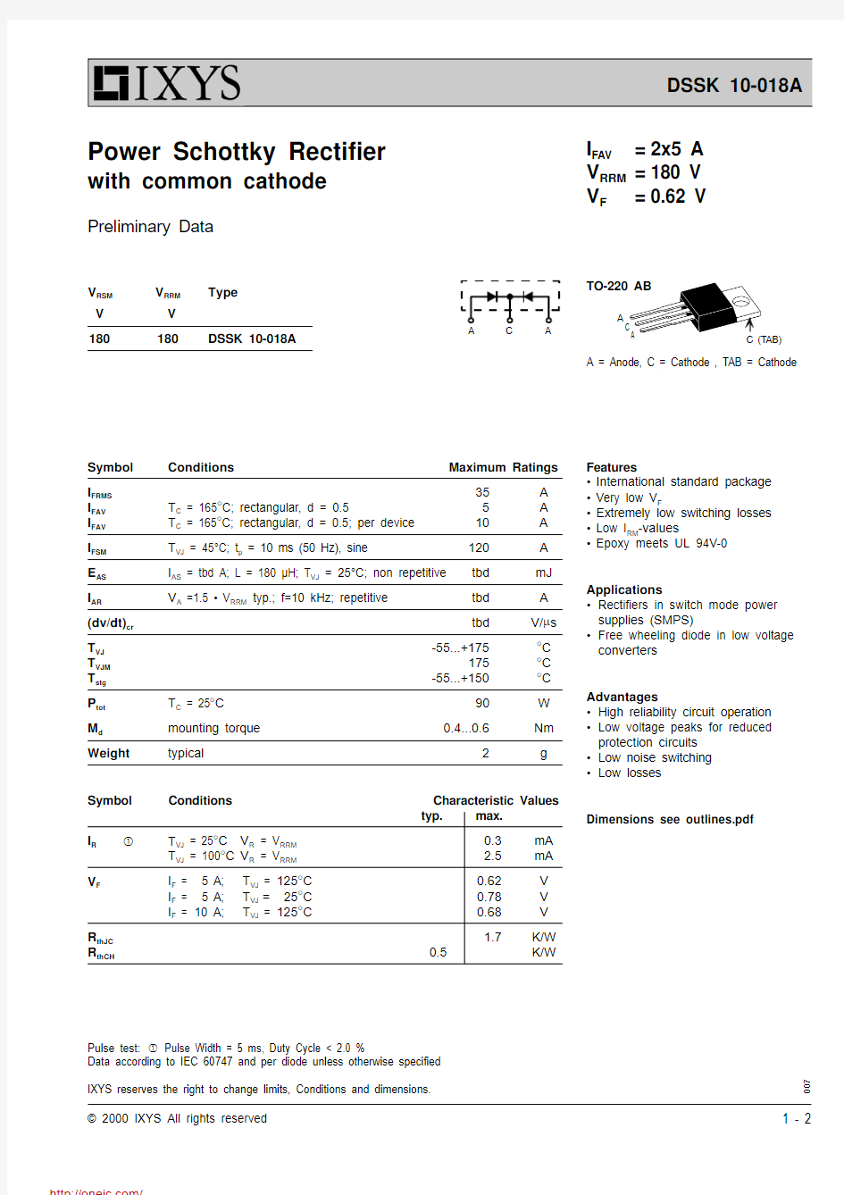
TO-220 AB
A C A
A = Anode, C = Cathode , TA
B = Cathode
Features
?International standard package ?Very low V F
?Extremely low switching losses ?Low I RM -values
?Epoxy meets UL 94V-0
Applications
?Rectifiers in switch mode power supplies (SMPS)
?Free wheeling diode in low voltage converters
Advantages
?High reliability circuit operation ?Low voltage peaks for reduced protection circuits ?Low noise switching ?Low losses
Dimensions see outlines.pdf
007
I FAV =2x5 A V RRM =180 V V F =0.62 V
Symbol Conditions
Maximum Ratings
I FRMS 35A I FAV T C = 165°C; rectangular, d = 0.5
5A I FAV T C = 165°C; rectangular, d = 0.5; per device 10A I FSM T VJ = 45°C; t p = 10 ms (50 Hz), sine
120A E AS I AS = tbd A; L = 180 μH; T VJ = 25°C; non repetitive tbd mJ I AR
V A =1.5 ? V RRM typ.; f=10 kHz; repetitive
tbd A (dv/dt)cr tbd
V/m s T VJ -55...+175
°C T VJM 175°C T stg -55...+150
°C P tot T C = 25°C 90W M d mounting torque 0.4...0.6
Nm Weight
typical
2
g
V RSM V RRM
Type
V V 180
180
DSSK 10-018A
Symbol Conditions
Characteristic Values typ.max.
I R
T VJ = 25°C V R = V RRM 0.3
mA T VJ = 100°C V R = V RRM 2.5mA V F
I F = 5 A;T VJ =125°C 0.62V I F = 5 A;T VJ =
25°C 0.78V I F =10 A;
T VJ =125°C
0.68V R thJC 1.7
K/W R thCH
0.5
K/W
Preliminary Data
0.0
0.20.4
0.6
0.8110
100
I F
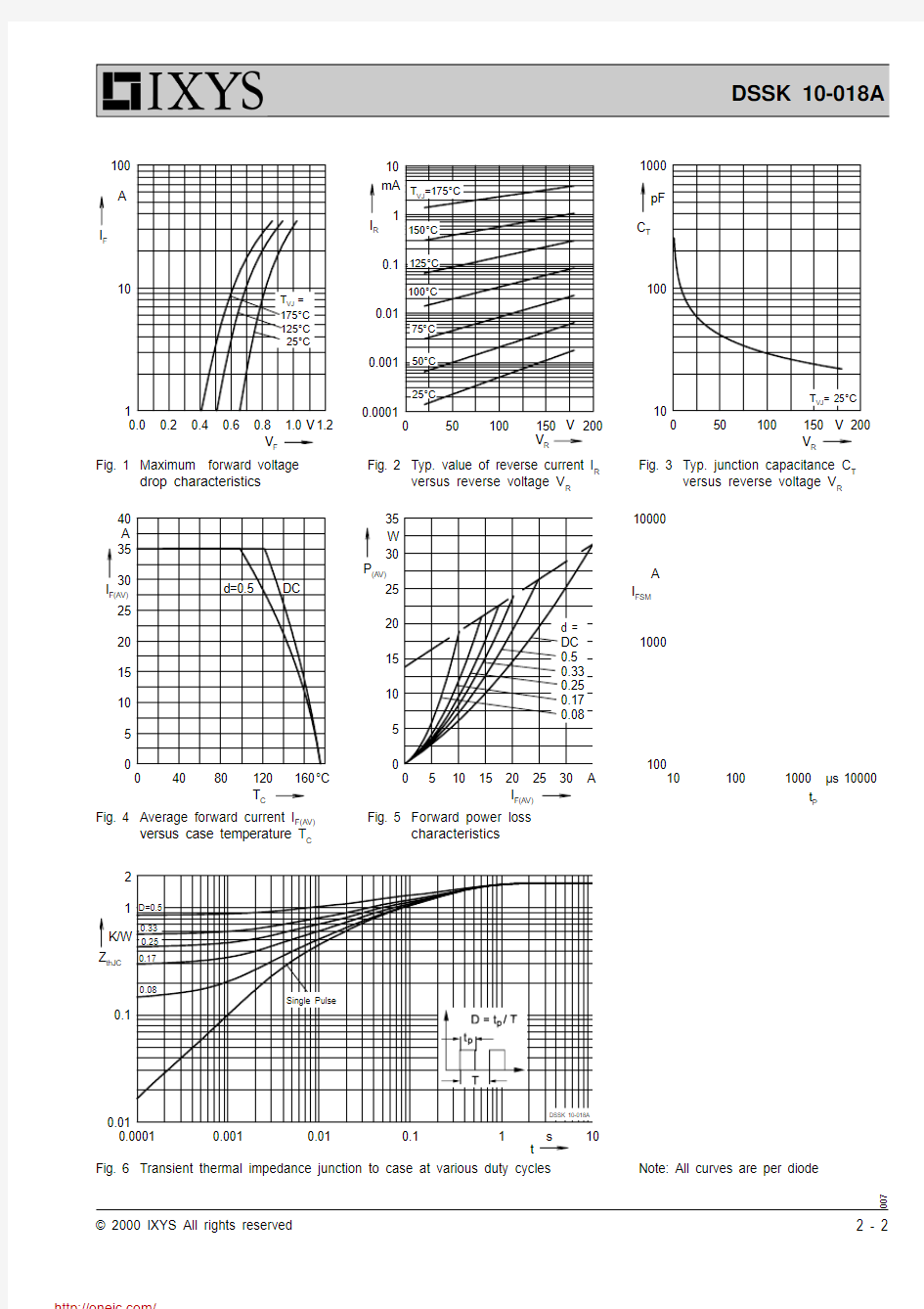
A Fig. 3Typ. junction capacitance C Fig. 2Typ. value of reverse current I R
versus reverse voltage V R
Fig. 1Maximum forward voltage
drop characteristics
Fig. 6Transient thermal impedance junction to case at various duty cycles 007
Note: All curves are per diode
分销商库存信息: IXYS
DSSK10-018A