DZ23C3V0-7-F中文资料
Lead-free
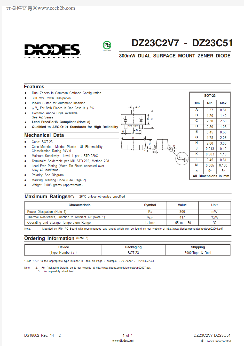
DZ23C2V7 - DZ23C51
300mW DUAL SURFACE MOUNT ZENER DIODE
·Dual Zeners in Common Cathode Configuration ·300 mW Power Dissipation
·Ideally Suited for Automatic Insertion ·D V Z For Both Diodes in One Case is £ 5%·Common Anode Style Available See AZ Series
·Lead Free/RoHS Compliant (Note 3)
·Qualified to AEC-Q101 Standards for High Reliability
Features
Maximum Ratings @T A = 25°C unless otherwise specified
·Case: SOT-23
·Case Material: Molded Plastic. UL Flammability Classification Rating 94V-0
·Moisture Sensitivity: Level 1 per J-STD-020C ·Terminals: Solderable per MIL-STD-202, Method 208·Lead Free Plating (Matte Tin Finish annealed over Alloy 42 leadframe). ·Polarity: See Diagram
·Marking: Marking Code (See Page 2)·
Weight: 0.008 grams (approximate)
Mechanical Data
Note: 2. For Packaging Details, go to our website at https://www.360docs.net/doc/303172711.html,/datasheets/ap02007.pdf. 3. No purposefully added lead.
* Add “-7-F” to the appropriate type number in Table on Page 2 example: 6.2V Zener = DZ23C6V2-7-F.(Note 2)
Ordering Information
Note: 1. Mounted on FR4 PC Board with recommended pad layout which can be found on our website at https://www.360docs.net/doc/303172711.html,/datasheets/ap02001.pdf.
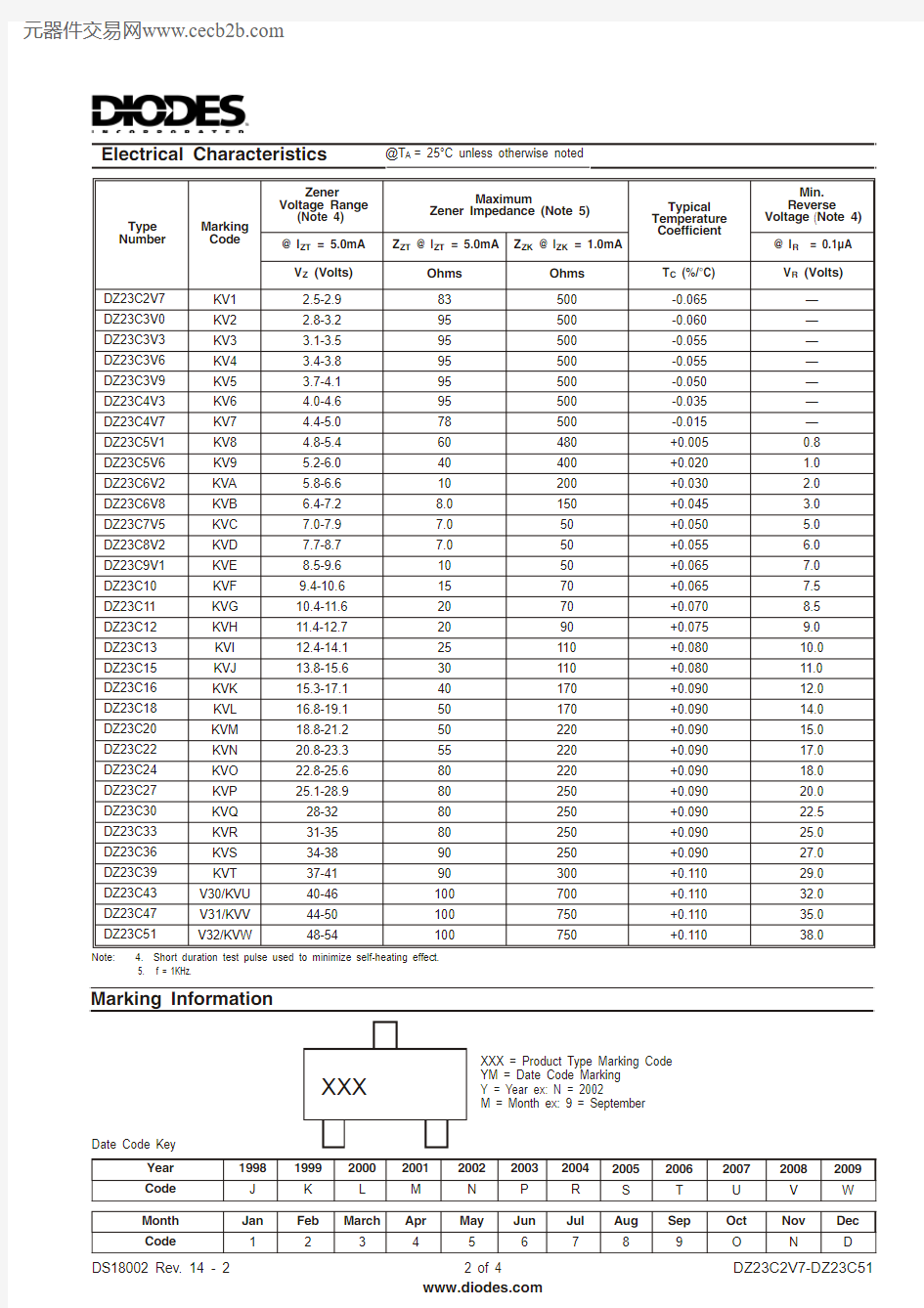
Electrical Characteristics
@T A = 25°C unless otherwise noted
Note: 4. Short duration test pulse used to minimize self-heating effect. 5. f = 1KHz.
Date Code Key
XXX = Product Type Marking Code YM = Date Code Marking Y = Year ex: N = 2002
M = Month ex: 9 = September
XXX
Y M
Marking Information
2
4
6
8
10
10
20
30405060708090100I , Z E N E R C U R R E N T (m A )
Z V , ZENER VOLTAGE (V)
Z Fig. 4 Zener Breakdown Characteristics
010
20
30
I , Z E N E R C U R R E N T (m A )
Z V , ZENER VOLTAGE (V)
Z Fig. 3 Zener Breakdown Characteristics
10203040
010
20
30
40
50
1
2345678910
I , Z E N E R C U R R E N T (m A )
Z V , ZENER VOLTAGE (V)
Z
Fig. 2 Zener Breakdown Characteristics
T , Ambient Temperature, (°C)
A Fig. 1 Power Derating Curve
P , P O W E R
D I S S I P A T I O N (m W )
d 20010030004005000
100
200
C , T O T A L C A P A C I T A N C E (p F )
T 10
100
1000
V , NOMINAL ZENER VOLTAGE (V)
Z Fig. 5 Total Capacitance vs Nominal Zener Voltage
IMPORTANT NOTICE
Diodes Incorporated and its subsidiaries reserve the right to make modifications, enhancements, improvements, corrections or other changes without further notice to any product herein. Diodes Incorporated does not assume any liability arising out of the application or use of any product described herein; neither does it convey any license under its patent rights, nor the rights of others. The user of products in such applications shall assume all risks of such use and will agree to hold Diodes Incorporated and all the companies whose products are represented on our website, harmless against all damages.
LIFE SUPPORT
Diodes Incorporated products are not authorized for use as critical components in life support devices or systems without the expressed written approval of the President of Diodes Incorporated.