PD-NPM-0305EP中文资料

PD-NPM-0305EP
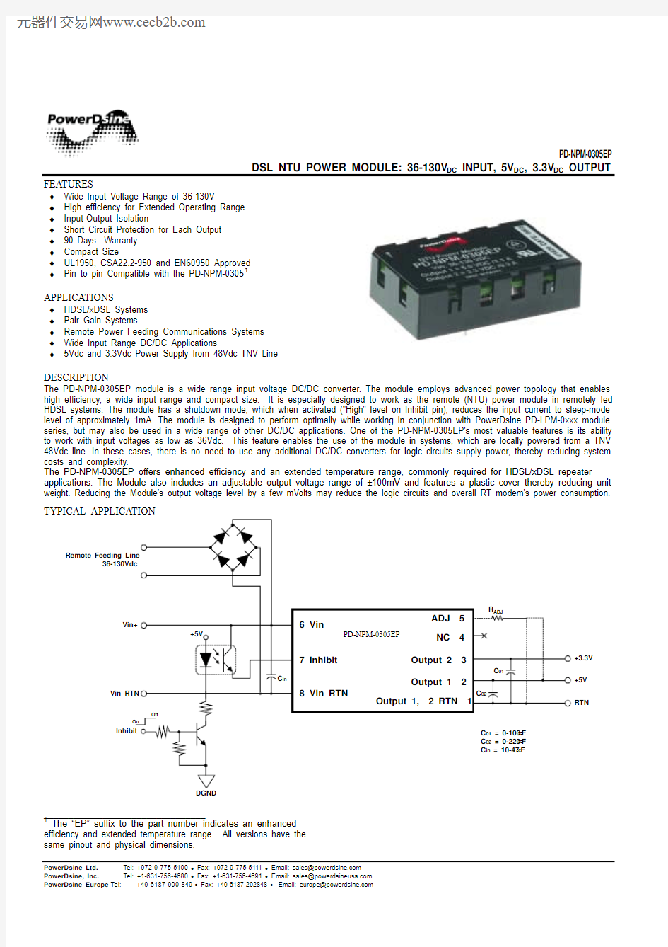
DSL NTU POWER MODULE: 36-130V DC INPUT, 5V DC , 3.3V DC OUTPUT
PowerDsine Ltd. Tel: +972-9-775-5100 ? Fax: +972-9-775-5111 ? Email: sales@https://www.360docs.net/doc/3210579520.html, PowerDsine, Inc. Tel: +1-631-756-4680 ? Fax: +1-631-756-4691 ? Email: sales@https://www.360docs.net/doc/3210579520.html, PowerDsine Europe Tel: +49-6187-900-849 ? Fax: +49-6187-292848 ? Email: europe@https://www.360docs.net/doc/3210579520.html,
FEATURES
? Wide Input Voltage Range of 36-130V
? High efficiency for Extended Operating Range ? Input-Output Isolation
? Short Circuit Protection for Each Output ? 90 Days Warranty ? Compact Size
? UL1950, CSA22.2-950 and EN60950 Approved ? Pin to pin Compatible with the PD-NPM-03051
APPLICATIONS
? HDSL/xDSL Systems ? Pair Gain Systems
? Remote Power Feeding Communications Systems ? Wide Input Range DC/DC Applications
? 5Vdc and 3.3Vdc Power Supply from 48Vdc TNV Line
DESCRIPTION
The PD-NPM-0305EP module is a wide range input voltage DC/DC converter. The module employs advanced power topology that enables high efficiency, a wide input range and compact size. It is especially designed to work as the remote (NTU) power module in remotely fed HDSL systems. The module has a shutdown mode, which when activated ("High" level on Inhibit pin), reduces the input current to sleep-mode level of approximately 1mA. The module is designed to perform optimally while working in conjunction with PowerDsine PD-LPM-0xxx module series, but may also be used in a wide range of other DC/DC applications. One of the PD-NPM-0305EP's most valuable features is its ability to work with input voltages as low as 36Vdc. This feature enables the use of the module in systems, which are locally powered from a TNV 48Vdc line. In these cases, there is no need to use any additional DC/DC converters for logic circuits supply power, thereby reducing system costs and complexity.
The PD-NPM-0305EP offers enhanced efficiency and an extended temperature range, commonly required for HDSL/xDSL repeater applications. The Module also includes an adjustable output voltage range of ±100mV and features a plastic cover thereby reducing unit weight. Reducing the Module’s output voltage level by a few mVolts may reduce the logic circuits and overall RT modem's power consumption.
+5V
Inhibit
On
Off
+3.3V +5V
RTN
Vin+
Vin RTN
6 Vin
8 Vin RTN
Output 1 2
Output 1, 2 RTN 1
NC 4
7 Inhibit
Output 2 3
C 01
C 02
C in
Remote Feeding Line
36-130Vdc
ADJ 5
PD-NPM-0305EP
C 01 = 0-100μF C 02 = 0-220μF C in = 10-47μF
R ADJ
V o u t -
V o u t +
_________________________________ 1
The “EP” suffix to the part number indicates an enhanced efficiency and extended temperature range. All versions have the same pinout and physical dimensions.
PD-NPM-0305EP
DSL NTU POWER MODULE: 36-130V DC INPUT, 5V DC , 3.3V DC OUTPUT
PD-NPM-0305EP
ABSOLUTE MAXIMUM RATINGS*
Input Voltage ................. - 0.5 to 140V Inhibit Input Voltage ................. - 0.5 to 130V Storage Temperature ................. - 40°C to 100°C Isolation Voltage (Input to Outpu1, Output 2) ................. 1500V
* These are stress ratings. Exposure of the device to any of these conditions may adversely effect long-term reliability. Proper operation other than as specified in the PERFORMANCE / FUNCTIONAL SPECIFICATIONS is not implied.
PERFORMANCE / FUNCTIONAL SPECIFICATIONS
Unless otherwise indicated, the data below applies to the specified operating input voltage, load (resistive), and temperature range. C in =10μF. Parameter Conditions Min Typ Max Units
Input Data
Input Voltage 4
36 130 V Inhibit Threshold 0.4 2.4 V Input Current At Minimum Input Voltage, Full Load 280 mA Input Reflected Ripple Measured on 10μF ESR ≤1? external capacitor. BW=20MHz
200 mV Output Data
Output 1 Voltage 1
Output 2 Voltage 1
Maximum Load Maximum Load 4.95 3.2 5.05 3.3 5.15 3.4 Vdc Vdc Total Output Power 6.5 W Output 1 Current Output 2 Current 0.22 0.03 1.1 0.3 A A
Total Regulation 2
Line/Load/Temperature Output 1 Output 2 Outputs are proportionally loaded: Imin < Iload < Imax Imin < Iload < Imax
±1 ±2
% % Output 1 Cross Regulation Output 2 Cross Regulation Output1=Full Load, Imin ≤ Output 2 ≤ Imax Output2=Full Load, Imin ≤ Output 1 ≤ Imax ±2.0 ±2.5
%
% Ripple and Noise 6
Output 1 Output 2 Measured on 0.1μF ceramic capacitor BW=20MHz @25°C Ambient Temperature 50 50 70 70 mVp-p mVp-p Hold-Up Time Measured with external input capacitor Cin = 47μF, Output Power = 6W. Vin Min = 70V, Maximum Load 10 mSec
Efficiency
Vin = 72V, Load = 6.5W Vin = 72V, Load =3.5W 80 77 % %
Switching Frequency
125 KHz Output Short Protection Safe period for short circuit on either or both outputs. ∞
Sec Reliability
MTBF Continuous Operation @30°C Ambient Temperature.
Prediction method:
Bellcore TR-332 Issue 5, Method 1 Case III
Software Version 5.30
1,000,000 Hours Environmental Data
Ambient Temperature 5 Continuous Operation. No Derating -40 +85 °C
Relative Humidity Non-Condensing, Per IEC 68-2-56 93 % 1. The PD-NPM-0305EP allows for up to ±100mV output voltage adjustment for both Output 1 and Output 2. Connecting a resistor, R ADJ ,
between Pin 5 and Pin 1 will increase the output voltage of Output 1and Output 2. Connecting a resistor, R ADJ , between Pin 5 and Pin 2
will decrease the output voltage of Output 1and Output 2. )
(K R 51 6.25V V ADJ Typical -out out ?+=±
2. Output currents below the minimum rate may cause total regulation to divert from rated specifications. In cases where Output 1 or Output
2 is not in use, the unused output should be loaded for minimal current consumption with a resistor.
3. The unit is designed to meet EN55022 Class B Standard with an external EMI filter. For filter design recommendations, refer to the
PowerDsine xDSL Power Modules Application Note.
4. In order to comply with the EN60950 standard in telecommunication networks, the unit's input voltage must not exceed 120Vdc.
5. In order to comply with the EN60950 standard, the maximum operating ambient temperature must be 85°C.
6. Output ripple may reach 150mV at ambient temperatures below -10°C.
7. When the Inhibit function is not used it is recommended to permanently connect the Inhibit terminal to Vin RTN (pin 8).
PD-NPM-0305EP
DSL NTU POWER MODULE: 36-130V DC INPUT, 5V DC and 3.3V DC OUTPUT
PowerDsine Ltd. Tel: +972-9-775-5100 ? Fax: +972-9-775-5111 ? Email: sales@https://www.360docs.net/doc/3210579520.html, PowerDsine, Inc. Tel: +1-631-756-4680 ? Fax: +1-631-756-4691 ? Email: sales@https://www.360docs.net/doc/3210579520.html, PowerDsine Europe Tel: +49-6187-900-849 ? Fax: +49-6187-292848 ? Email: europe@https://www.360docs.net/doc/3210579520.html,
MECHANICAL DETAILS
PIN CONNECTIONS
Pin # Function Description
1 Output 1,
2 RTN Return line for Output 1 and Output 2
2 Output 1 Primary output, regulated, 5.05V/1.1 Amp maximum
3 Output 2 Secondary output, regulated, 3.3V/0.3 Amp maximum
4 NC Not connected
5 ADJ (NC) Output Voltage Adjustment
6 Vin Positive supply terminal. Typically feeds from the line through bridge rectifier to prohibit voltage reversal.
7 Inhibit
Logic input, relative to Vin RTN (pin 8) with an internal pull down resistor. High logic level will inhibit operation of the module, and the device’s current consumption will drop to an idle level. Leaving this pin unconnected, or connecting it to a low logic level, will enable the outputs.
When the Inhibit function is not used it is recommended to permanently connect the Inhibit terminal to Vin RTN (pin 8).
8 Vin RTN
Negative supply terminal pin. Typically feeds from the line through the bridge rectifier prohibit voltage reversal.
PD-NPM-0305EP V11 0900
Bottom View
Side View
mm
Inch Top View
NTU Power Module
Name Plate
D C
B
A
G
F
A
E
B C D E
F G H
H
K
K 5431
2678
DIMENSIONS
52.00±0.5030.00±0.5011.42±0.5022.86±0.255.08±0.255.00±0.5012.50 MAX 3.00±0.253.00±0.25
2.05"±0.02"1.18"±0.02".45"±0.02".90"±0.01".20"±0.01".196"±0.02".492" MAX 0.117"±0.01"0.117"±0.01"
SQUARE PIN