LTV-826_PDF_C10786_2014-03-04
FEATURES
* Current transfer ratio January 2010 ( CTR : MIN. 50% at I F =5mA, V CE =5V )
* High input-output isolation voltage
( V iso =5,000Vrms )
* Response time
( t r : TYP. 4μs at V CE =2V, I C =2mA, R L =100? )
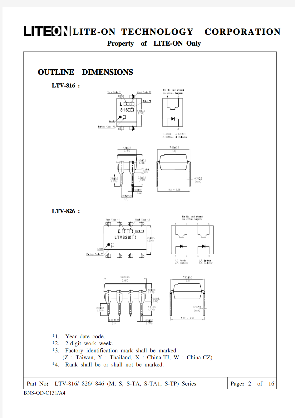
* Dual-in-line package :
LTV-816 : 1-channel type
LTV-826 : 2-channel type
LTV-846 : 4-channel type
* Wide lead spacing package :
LTV-816M : 1-channel type
LTV-826M : 2-channel type
LTV-846M : 4-channel type
* Surface mounting package :
LTV-816S : 1-channel type
LTV-826S : 2-channel type
LTV-846S : 4-channel type
* Tape and reel packaging :
LTV-816S-TA : 1-channel type
LTV-816S-TA1 : 1-channel type
LTV-816S-TP : 1-channel type
LTV-826S-TA1 : 2-channel type
* Safety approval
UL / CSA / FIMKO / NEMKO / DEMKO / SEMKO / VDE* approved
*Required “V” ordering option
* RoHS compliance
ABSOLUTE MAXIMUM RATING
( Ta = 25°C ) PARAMETER SYMBOL RATING UNIT
Forward Current I F50 mA INPUT
Reverse Voltage V R 6 V
Power Dissipation P 70 mW
Collector - Emitter Voltage V CEO80 V
Emitter - Collector Voltage V ECO 6 V OUTPUT
Collector Current I C50 mA
Collector Power Dissipation P C150 mW Total Power Dissipation P tot200 mW
*1 Isolation Voltage V iso5,000 Vrms Operating Temperature(LTV- 826 / 846)T opr-30 ~ +100 °C
Operating Temperature (LTV-816)T opr-30 ~ +110 °C
Storage Temperature T stg-55 ~ +125 °C
*2 Soldering Temperature T sol260 °C
*1. AC For 1 Minute, R.H. = 40 ~ 60%
Isolation voltage shall be measured using the following method.
(1) Short between anode and cathode on the primary side and between collector and
emitter on the secondary side.
(2) The isolation voltage tester with zero-cross circuit shall be used.
(3) The waveform of applied voltage shall be a sine wave.
*2. For 10 Seconds
RANK TABLE OF CURRENT TRANSFER RATIO CTR
MODEL NO. RANK MARK CTR ( % )
LTV-816 L 50 ~ 100
LTV-816 A 80 ~ 160
LTV-816 B 130 ~ 260
LTV-816 C 200 ~ 400
LTV-816 D 300 ~ 600
LTV-816 L or A or B or C or D 50 ~ 600
LTV-8※6 B 130 ~ 260
LTV-8※6 B or C or BC 130 ~ 400
LTV-8※6 C 200 ~ 400
LTV-8※6 C or D or CD 200 ~ 600
LTV-8※6 B、BC、C、CD or No mark 50 ~ 600
※ = 2 or 4
CONDITIONS I F = 5 mA V CE = 5 V Ta = 25 °C
TEMPERATURE PROFILE OF SOLDERING REFLOW
(1)One time soldering reflow is recommended within the condition of temperature and time
profile shown below.
1.Wave soldering
– 260 °C / 10 sec
2.IR reflow
Profile Item Condition
Preheat
– Temperature Min (Ts min) – Temperature Max (Ts max) – Time (min to max) (ts)
150 °C 180 °C 90 ± 30 sec
Soldering zone
– Temperature (T L) – Time (t L)
250 °C 10 ~150 sec
Peak temperature (Tp) 260 °C Ramp-down rate 3 ~ 6 °C/sec
Notes:
- Lite-On is continually improving the quality, reliability, function or design and
Lite-On reserves the right to make changes without further notices.
- The products shown in this publication are designed for the general use in electronic applications such as office automation equipment, communications devices,
audio/visual equipment, electrical application and instrumentation.
- For equipment/devices where high reliability or safety is required, such as space
applications, nuclear power control equipment, medical equipment, etc, please
contact our sales representatives.
- When requiring a device for any ”specific” application, please contact our sales in advice.
- If there are any questions about the contents of this publication, please contact us at your convenience.
- The contents described herein are subject to change without prior notice.