外文翻译2

Structural Eng./Earthquake Eng., JSCE, Vol.25, No.2, 47s-59s, 2008
(Copy of Dobokugakkai Ronbunsyuu A Vol.64 No.4, 692-704, 2008.11)
水平循环荷载作用下砌体墙的抗剪承载力预测
Abdelkrim BOURZAM1, Tetsuro GOTO2 and Masakatsu MIYAJIMA3
1PhD cand., Kanazawa University (Kakuma-machi, Kanazawa, Ishikawa 920-1192, Japan)
E-mail: bourzam@https://www.360docs.net/doc/3715712914.html,
2Senior Researcher, Housing Dept. of National Institute of Land and Infrastructures Management (NILIM) of Tsukuba
(1, Tatehara, Tsukuba, Ibaraki 305-0802, Japan)
E-mail: goto-t92in@nilim.go.jp
3Professor, Dept. of Civil Eng., Kanazawa University (Kakuma-machi, Kanazawa, Ishikawa 920-1192, Japan)
E-mail: miyajima@t.kanazawa-u.ac.jp
这项研究描述了一个预测砖砌墙未能按对角分裂的剪切能量的分析和建议,最大剪切力以连接柱强化部分的销作用和平面砌体结构面板的剪切能量来计算,实验测试结果和文献收集的数据被用来验证这一提出的方法。实验测试有关的两个密闭粘土砖墙受到不同程度的重力荷载和横向循环荷载。在文献中发现了一些关于刚度退化的适用性经验公式的研究。使用推荐方法预测的横向抗力与所有的数据构成了较好的相关性。
关键词:密闭砖墙砖面板循环荷载销钉作用刚度抗剪承载力
1.简介
在楼房的砖石结构体系中,支柱之间的裂口在地震时是最脆弱的;而墙壁的破坏大多数情况是由于剪力的作用。不过,在现有的多种解决方案中如把钢筋和砖砌墙、板之间通过捆绑进行加固加强等来补救这一缺点的措施是非常重要的。
密闭砌体墙分别由一些被称作连接柱(约束柱)、连接梁或重力梁包围的小型现浇钢筋混凝土柱和承重墙组成。这个系统就是必须抵抗纵向和横向荷载的墙,RC 连接柱和连接梁的目的是限制砌筑面板,从而提高了墙体的变形能力,改善由于循环侧向加载的影响作用,并保证与其他墙壁和地板的连接。
这种RC连接柱和连接梁应该具有足够的截面尺寸和配筋率来抵抗地震的倾覆力矩和剪切力。根据欧洲规范的要求1)2),对于纵向和横向的阻力没有作用的约束竖杆在计算时都应该考虑到。钢筋的数量仅仅取决于经验,也就是建筑物的高度和大小。
在阿尔及利亚抗震规范中3),密闭墙被认为是三角系统(桁架系统),由被包围的构造柱和粱所形成,并且在砌体墙中形成由活动支柱构成的对角因素容易受到影响。
众所周知,弯曲破坏在抗震设计中是有利的,因为这样伴随着较大的塑性变形和能量的吸收、耗散4)。剪切破坏,另一方面,在有限的塑性条件下显得更脆,普通密闭砌体可以在一定程度上弥补这一弱点。
迄今为止很少有实验研究了密闭砌筑墙体和建筑的抗震性能,依靠可靠的密闭墙板设计经验进行计算的过程已经完善。
通过对单层砌体房屋的一系列测试,振幅随着施加的动态正弦位移增加而增加,已经推断出垂直连接柱能够显著提高砌体房屋的塑性,但对横向阻力影响不大5)。类似的结论已通过静态循环试验得到公认,5),6),7)。低质量砌体的水平墙面板与密闭性砌体墙面板之间的破坏行为相关性研究也得以展开8)9),展现了改善砌体抗震性能的原理。不过,直到1997年也没有试图去预测解析密闭砌体墙的抗震性能10)。在这方面,Toma?evi?和Klemenc11)提出了一个方法来预测密闭砌体墙抗剪能力,支柱抗震性能由考虑到的连接梁、连接柱和砌体面板之间相互作用力的影响来决定,并附加垂直连接粱的作用(销钉作用)。在这种方法中,由这些连接柱组成的横向强化结构所带来的剪切应力在计算中不被考虑。相同试件的剪切应力计算采用由这些作者研究出的系统的公式,揭示了一个从23.6%到53.8%的高估的抗剪能力(试验剪切应力)(取决于测试的样本11))。这种巨大的高估值主要来源于作者所述连接柱与砖面板之间的相互作用。不过,作者们通过改变相互作用系数来模拟密闭填充砌体墙系统的相互作用情况,反之,密闭墙的施工是完全不同于填充墙的施工的。
在2003年和2006年的Hori et al12),13)中,提出了一种对密闭混凝土空心砌块墙体的抗震分析方法,作
者采用了刚体弹簧元;对侧向荷载结构系统的抵抗机制,这种抵抗机制是由连接柱拉伸侧的拉应力与混凝
土砌块砌体墙的斜向压应力所组合而成。
在这项研究工作中,Toma?evi?和Klemenc11)的
主要思想(砌体面板和构造柱组合的抗剪能力)不包
括维持互动效应和做其他的尝试,一个新的分析性方
法来预测因对角分裂而破坏的密闭砌体墙的抗剪能力,且以试验数据结果为依据,在一定的范围内保持一致。
这项研究主要包括两部分。第一部分涉及用拟定的方法解决预测密闭砌体墙最大剪切能力,墙体的总剪切能力是由砖面板与RC(连接柱)提供的剪切能力的累加。在此方法中的砖面板被视为均匀各向同性材料,对于评价普通的砌体墙抗剪强度的基本方程,可以由考虑到的弹性基本理论的假设推导出字典- 查看字典详细内容。连接柱抗力由RC竖直钢筋的销钉作用和箍筋效果计算而来。第二部分是关于验证根据实验研究和文献收集的数据的建议和方法。实验研究是在两个完全密闭粘土砖墙CM30J- 1和CM30J- 2上,试件分别受到不同层次的重力负荷0.4 MPa和1.4 MPa,以及面内循环横向载荷。试件cm30j-1的测试由作者在近期完成,而类似第一个被测试的其它试件是在1993年3月14)。从不同的出版作品所收集的代表各种不同特点的密闭砖墙的数据,如给出的表3,其中砌筑材料特性,柱截面,以及强化使得高度与长度的比率h/l和重力负载的表达细节化了。这项研究还包括砌墙刚度降低的评价。此外,还核实了Toma?evi?和Klemenc11)关于刚度降低的经验公式的有效性,同一个作者的试验数据是由三个1:5的缩小的h/l率为1.5且附加了0.28MPa重力负载的密闭砌体墙模型(AH-1,AH-2,AH-3)得来,采用了样本CM30J-1和CM30J-2的当前试验结果(见表2)。
2.所用材料的试用指标和机械特性
由砖石建筑系统可知,有两种可能发生的剪切破坏主要类型:
-对角分裂造成的剪切破坏
-砂浆接头分离造成的剪切破坏
本文仅研究由对角分裂造成的破坏情形。这种破坏的机制下,在绝大多数抗震规范中报道并通过了砖面板可当作均质材料(例如:早期设计规范,或最近的欧洲规范61))。此外,根据弹性基本理论,影响砌体抗拉强度F
t
的因素是与砖块和砂浆质量有关,其形状因子为β,重力荷载强度为σN,砌体断裂面A m影响砖面板的抗剪强度,如公式(3a)所示。抗剪公式
(3b)所示为当墙体承受一个重要的重力载荷σ
N
时的
压缩强度F
m
。在砖柱的影响下,两个砖柱底部连接的砖面板形成了"连接销"的效果。砖面板剪切公式(9a)与(9b)附加了这里具有“连接销”效果部分的抗剪结果。
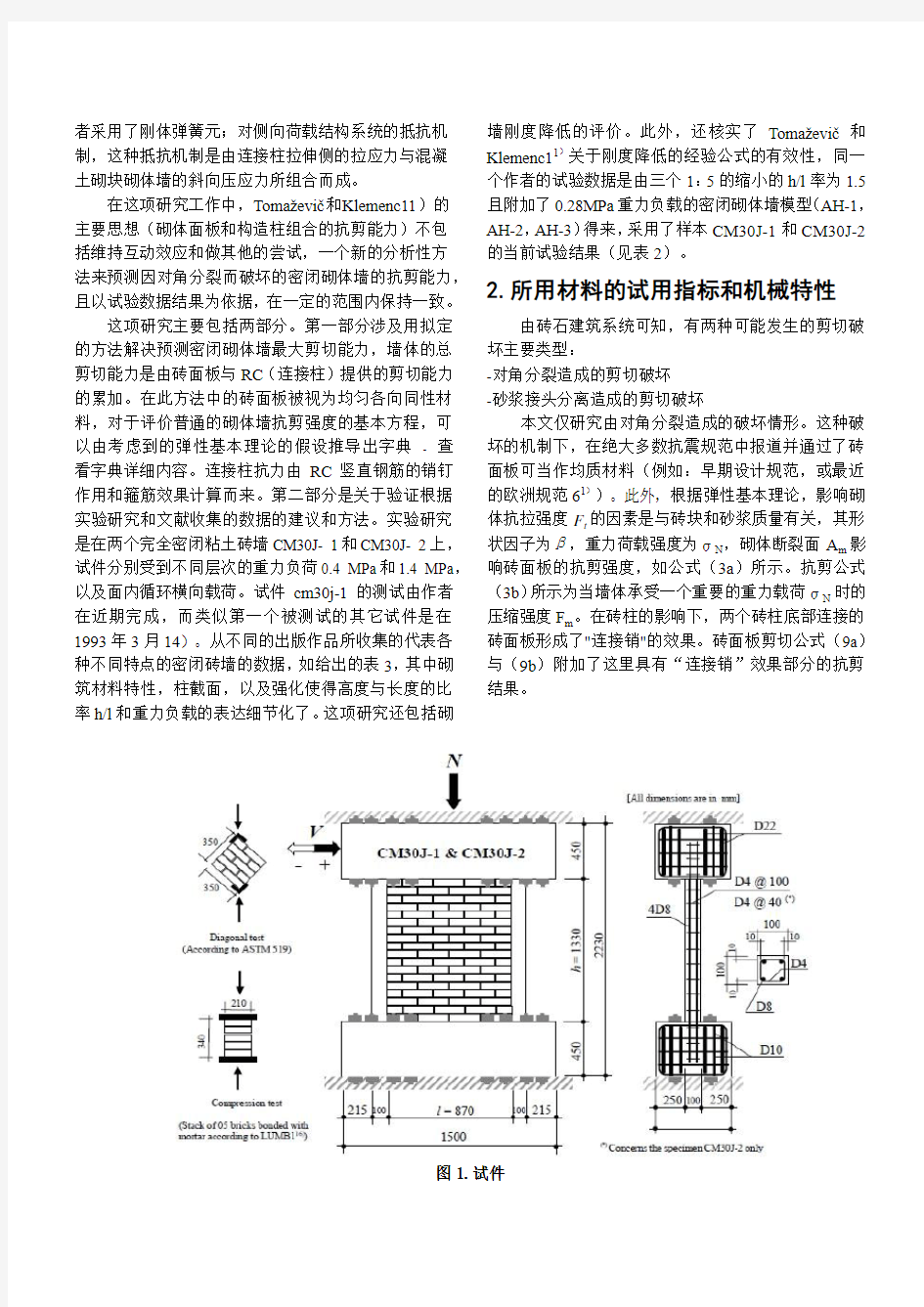
图1.试件
在这种由于砂浆接头分离与基体发生剪切或单纯由基体发生剪切的砌体墙破坏的情况下,均质假设不再适用,并为非均质优势留下了一定的空间,诸如在砖块和砌体间的压力连接处的砌体本身的剪切、砖块的抗拉强度等,在评估转面板的抗剪性能时应该被考虑进去。这种由于接头分离或砂浆基体剪切破坏常常发生在使用了劣质砌体(低压缩率低剪切强度)所建造的墙体上,并且此种墙体基本不能承重。
尽管需要高昂的费用以及在实验室开展实验的诸多困难,当务之急仍然是无可争议的确定这种系统结构的力学特点。
之前介绍的测试试件CM30J-1、CM30J-2,都有一个全尺度的H/L=1.5的由RC包围的通用窗立柱。墙体面板由名义尺寸为210×100×60mm且具备30MPa 压缩强度的日本实心粘土砖复合而成。这些砖块间填充有清水泥砌体,具有10mm的连接厚度和27MPa的压缩强度。混凝土被用来构造环绕框架,具有20MPa 的压缩强度。主杆(垂直加强)的屈服强度在样本CM30J-1中为415MPa,箍筋强度为600MPa。在样本CM30J-2中所有的钢制材料主杆屈服强度均为385MPa。样本的尺寸、加强的排列形式以及构件部分如图1所示。
墙是在钢筋混凝土梁的基础上竖立。在建立转平面及RC连接柱之后在顶部灌注一个类似的梁。这个在两根柱间垂直加强圈梁提供了足够的锚固作用,并且提供了足够的转移附加水平负载能力。RC梁被固定在反作用框架上,如图2所示。
图2.加载系统
在标准LUMB116)下,测试了三堆由五块转块连接而成的菱形区域,且每处菱形区域与墙体表面间连接有10mm厚度的砌体,得到了菱形堆的压缩强度f,
m
为9MPa。
在标准ASTM519(ASTM C1391)下测试三块以对角压缩负载下的矩形砌体堆样本(350x350x100mm),并得到砌体墙的抗拉强度F t的值(F t=1.1MPa)。此值被用来确定矩形样本中心的主拉应力15)17)18),为
0.7336τ,其中τ=0.707P d/A为样本的平均剪应力(P d 与A分别为最大对角压缩负载和样本截面积)。
砌体墙的弹性模量和剪切弹性模量以压缩强度的1/3确定,分别为E m=8241MPa,G m=1723MPa,
E c=18320MPa,G c=7633MPa。
3.负载系统与测量
密闭式砌体墙(CM30J-1与CM30J-2)的试验借助于B.R.I(日本建筑研究院)结构试验部门的试验设备来实现,如图2所示。垂直与水平负载由电脑自控制的执行机构施加。水平位移由两个LVDT(线性可变差动变压器)位移传感器来测量。
在试验过程中,垂直负载由执行机构的垂直施压机构施加,对于样本CM30J-1与CM30J-2的钢梁和顶部RC梁施加的负载分别为0.4MPa与1.4MPa。前者的普通重力负载0.4MPa代表了一个四层建筑第一层的平均负载结果,而1.4MPa代表了一个仓库或特殊基础建筑的重要重力负载。
在样本上进行的循环荷载试验被认为是准静力试验,墙体已被施加了提高振幅的循环水平位移,并以斜角来表示,前一个值为1/3200,后一个值对应墙体的破裂。两个循环荷载由每一个振幅所形成。
砌体墙CM30J-1的滞回循环现象反映了测量后的横向负载和平均水平位移之间的关系,如图3所示。
图3. CM30J-1横向负载-位移滞回循环4.试验结果与实测机理
测试样本CM30J-1的试验行为经历了不同的场景。在第三个由斜角为1/1600影响的循环负载中,其横向负载V=--66.25kN,水平位移δ=--0.49mm,左RC连接粱的基部出现了小型水平弯曲裂缝。在基本处于同一负载水平的第四次循环负载(V=70.25kN,δ
=0.6025mm)中,在砖面板与左连接柱间的界面上出现了一些其他小型裂缝,与图4所示的在墙体支撑柱上观察到的对角裂缝相同。由与斜角为同一水平的负向负载迅速产生了若干对称裂缝。根据定义,这一步标志着墙体的裂缝极限(弹性极限)。
接下来,裂缝沿着最初由弹性极限所产生的裂缝样式发展变大并发散。
在由层间位移角为1/500影响的第九次循环负载时记录了最大的横向负载。这些最大剪切负载的平均值使得负载的正向与负向水平扰度分别为78kN与2.67mm。
水平的剧烈位移与图3所示的最后一个循环负载中横向负载的减少证明了墙体的可延伸性。此时,对角裂缝的CMOD(裂缝开口位移)也变得重要起来,这些裂缝穿过了连接柱,最终形成了角对角的对角剪切裂缝。
根据样本CM30J-2,收集到的数据14)仅包含了三个状态的极限数据,横向负载V
el
=101.4kN,在弹性极
限的状态下,位移δ
el
=0.61mm,最大抗力V w=160.5kN,
并最终使得水平位移δ
W
= 2.5 mm,最终的状态由一个
水平抗力V
f
=72.13kN与墙体破坏前最大位移δf = 12 mm来描述。测试样本CM30J-2经历了与CM30J-1相同的各种剪切破坏下的重力负载。换句话说,这种破坏是由开裂而出现,同时墙体的裂缝样式与图4所示样本CM30J-1的其中之一相类似。
5.剪切能力分析预测与刚度降低
图4. CM30J-1墙的最后裂纹格局
对于受压密闭砌体墙剪切强度的切实可行的计算方法,在试验与分析性力学行为数据有限且精度不高的情况下,是一个非常困难的工作。因为,可选材料的多样性和制造技术的缺陷使这种类型建筑材料的特征化和标准化变得十分复杂。
大部分研究工作和已有的标准,比如建筑工业的欧洲标准61),简化了砌体结构的变形行为,旨在提供实际的更容易的结构行为分析的标准。通常,这些标准建议,在使用一个线性模型砌体结构的时候,把它当作均质材料1),15)。
本文描述的这种方法可指导并分析预测密闭砌体墙的最大剪切能力,由砌体墙的砖面板剪切能力与R.C 连接梁提供的剪切能力所叠加。这种推荐方法仅适用于密闭砌体墙由对角破裂所引起的破坏形式(连接处分离造成的破坏不在本文探讨范围内)。
(1)密闭砌体墙的剪切能力
a)砖面板的贡献
根据一个替代理论,剪切破坏引起的对角裂缝由主压应力或承受垂直和横向负载4),10),15)的墙体所带来的两个主应力组合而形成。根据这些假设,对于砖块砌体墙中穿过砌体组织的对角类型裂缝的研究也变得容易解释了。
根据将砌体墙当作弹性、均质、各向同性的结构元素19),可由基础弹性理论推导出衡量平面砌体墙抗剪能力的等式。在将一个垂直负载N和一个横向负载V组合的情况下,墙体中部的压缩主应力与抗拉强度
σ
c
与σ
t
描述如下:
其中:
σ
N
=垂直负载N所引起的砖面板压应力平均值。
β=砖面板的高度与长度的比率h/l所影响的剪切应力散布因子(当h/l小于等于1时,β=1;当1< h/l <1.5时,β= h/l;当h/l ≥1.5时,β= 1.5)10)。
τ=横向负载V引起的平均剪切应力V/A
m
,βτ表示面板中性轴处的最大剪应力。
A m =砌体墙面板的水平横截面积。
在相同的前述前提下,当抗力V达到最大值
(V=V
m
, τ=τm=V m/A m)时,立即产生一个参考主拉
应力,成为砌体结构的抗拉强度(F
t
)。
由关键抗拉强度造成的剪切破坏平面砌体墙面板
的横向抗力V
m
,由公式(3a)得到:(这里原文有错,把(2)改成(3a))
在这个前提下(由关键抗拉强度引起的破坏),
当墙体的主拉应力σ
t
达到砖面板的抗拉强度时发生破坏10),15)。这个前提必须满足下列条件:
—由砌体墙提供的小到适度重力负载(低层建筑和传统住宅的情况)。以秘鲁砌体建筑外墙砌体结构代码
为基础,σ
N
≤0.5 MPa。
—脆裂或由分裂引起的破坏,但不是由连接处分离引起的破坏。
—在柱(墙)的中性轴或附近产生对角裂缝,并沿对
角发展。
在这种前提下,砌体结构的压缩强度f`
m 的贡献被
忽略,当砌体墙提供一个重要的重力负载的情况下(仓
库或一个特殊基础建筑的情况),公式(3a)会变得不那么精确。在对重力负载水平没有任何说明的情况下,Yokel与Fattal15),Sucuo?lu与McNiven4)认为墙体平面的两个主应力导致了破坏,并且这两个应力的组合满足Mohr-Coulomb破坏理论。在这些条件下,横向抗力如下所示:
其中:
F t= 0.5187f,m P d/(f,m—1.683P d)包含在Mohr破坏理论中4),15)。(P d和A分别是最大对角压缩负载和砌体结构样本截面,如图1对角试验所示)
f,m=根据LUMB1的说明,测试由五个砖块连接而成的棱柱中的砌体压缩强度(见图1)。
前面的前提考虑了这种脆性破坏和施加了对角裂缝路径的情况。
b)连接柱的影响
斜角变大时,连接柱的强化使得拉伸方向上强加了横向位移。在这种水平下,开裂的砌体面板压迫连接柱导致加强筋的拉伸。换句话说,这些RC约束部分可以防止砌体组织的倒塌,且能在垂直和水平方向上附加压应力;因此,可以通过垂直柱的销作用来传递一部分附加剪切。这种机制主要发生在砌体的拐角处。根据Priestley与Bridgeman21)对强化砌体墙的理论,可以用水泥浆(混凝土)上的三角压分布作用估算通过裂缝垂直加强的销梁强度,其最大值等于F c(见图5a);在这项研究中,仅当这些由连接柱箍筋的贡献类似于图5a所期望和描述的附加并反映在主梁上的反作用力R st时,Priestley与Bridgeman的理论可以被正确的扩展至密闭砌体墙的情况。
图5a.销作用现象下主梁上混凝土和箍筋的反作用力
这些垂直连接柱有效地提升了砌体墙的塑性,但是对横向剪切抗力5)(来源于两根连接柱的墙体最大总剪切抗力的20%)只有很小的作用,此时,减小连接柱间的网状钢筋比率也更为经济,通过增加两个连续箍筋间的距离S t。S t通常为(3/4)t22)或简化为“t”14),22),其中“t”为连接柱的宽度。同时根据已知,在角度正好为一个精确值α= 45o 23)时,墙体的四个拐角的RC连接柱中易产生剪切裂缝。
根据上述原因,剪切裂缝至多通过1或2个箍筋(这些箍筋以提供销作用的梁的拐点对称布置)。这种销作用现象的确切表示如图5a所示。这种作用是瞬间呈现的,且形成销作用的剪切应力分布如图5b所示。
图5b.销作用下的主梁剪切应力和瞬间分布
弯曲瞬间的力平衡公式:M max=主梁最大外力矩。R c = f cφl /2 =主梁上混凝土的反作用力。
f c=混凝土压缩强度。
φ=主梁直径。
R st = f yt A st =主梁上箍筋的反作用力((f yt与A st分别为箍筋的屈服应力和截面积)。
S t=两根连续箍筋间的距离。
因而得到:
M max,b =主梁最大内力矩。
f y =主梁屈服应力。
由公式(4)和(5)联合得到:
在推导出公式(6)(R c值被确定)之后,如图
5b,可通过叠加剪切应力图来得到单根梁销作用产生的最大剪切抗力值。此时:
将其代入,R c =F cφl /2,得到销长度2L的值。
当2L≤S t(箍筋布置在销钉长度以外的位置)时,箍筋不会对销钉机制所带来的剪切抗力有任何贡献,然而,这里仅参考混凝土的作用,因而混凝土的反作用力R c也要重新计算。
n根垂直柱的剪切抗力代表了连接柱的总抗力,等于:
在实际经验中,n通常等于8。
假设通过墙体发展的对角裂缝是通过墙体四个拐角处形成销钉作用的约束钢筋来发展的。钢筋中的剪切应力(由销钉作用产生)将附加在砖面板的剪切抗力中。因此,密闭砌体墙的最大剪切抗力V w为:1—由关键拉应力(主拉应力)造成的破坏:
2—由两个方向主应力组合造成的破坏:
(2)理想化的滞回包络曲线和刚度降低
a)滞回包络曲线
根据Toma?evi?10)的理论,实验性抗力包络曲线表示循环横向负载与对应位移之间的关系,这种理想化是一种三线性关系。
表1. 横向负载与墙体CM30J、AH*的相应位移下的实验和理论数据
由实验曲线的三组参数定义了三个极限状态:
——弹性(裂缝)极限状态:由当墙体出现主要裂缝
的横向负载(V el)和位移(δel)来确定,并改变了初始刚度。
——最大抗力状态:由当墙体抗力达到最大值时的横向负载(V el)和位移(δel)来指明。
——终极(最终)状态:由墙体破坏前一瞬间的横向抗力(V f)与最大对应位移(δf)来确定。
V el与V f凭经验确定:和
C cr=简化因子,大小为0.6~0.8。
C sd=强度退化因子,大小为0.4~0.8。
在计算V el与V f时,C cr=0.7,C sd=0.6(两个因子的范围平均值)。
这里忽略了由连接柱发生小范围变形所带来的贡
献11),在公式(10)中简单的用V m所替代。
剪切抗力的实验值和理论值参见表1。
b)刚度
刚度因素取决于材料组成的力学性能,几何条件
以及边界条件。
当给密闭砌体墙施加一个横向负载时,墙体会产
生一个水平位移δ(见图6)。这个位移是由弯曲造成
的扰度和公式(12a)中定义的剪切造成的变形叠加而
成。
其中,
K e=密闭墙体的有效刚度。
I w = tl3/12,墙体横截面惯性矩。
A w=墙体水平截面积。
1.2=矩形面剪切系数。
α=边界条件系数,悬臂梁α=3,固定墙体α=12。
E eq=等效弹性模量。
G eq=等效剪切模量。
图6. 横向负载下的固定式密闭砌体墙变形表2 样本CM30J与AH*的刚度正割值与刚度降低单点滞回包络线
将公式(12a)中的V以公式(12b)所替代,并
调项,得到弹性范围内的密闭砌体墙有效普遍刚度公
式,如下所示:
μ=附加约束条件墙体的约束系数,悬臂梁墙体μ=3.33,固定式墙体μ=0.83。
在弹性范围内,刚度的正割值K以有效刚度K e 和破坏系数I d10),11)确定的方程计算。a,b=刚度退化参数。
I d=破坏系数定义如下:
I d=0.25:墙体出现第一个明显对角裂缝(裂缝极限)。
I d=0.50:形成对角裂缝网络。通常,在达到最大抗力时取得。
I d=0.75:裂缝宽度增加。砌体墙组织中部的破坏以及墙体压缩区域砌块与砌体的分离。
I d=1.00:严重破坏(待修复)或墙体破坏。以分析前述试验结果而得到10),或者在I d=1.00
时,刚度的正
割值仅以墙体有效刚度K e的2%~5%描述。
根据实验测试条件,K e对应的I d=0.25,终极(极限)强度的正割值对应的I d=0.75,代表了K e值的5%,如表2所示。
刚度退化参数a和b分别为1.805和0.451,由当此两种边界条件(K=Ke,Id=0.25)和(K=Kf=5%Ke ,Id=0.75)同时在公式(15)中做了替换得来。
在这种期望下,公式(15)变为:
在这项研究中,墙体刚度的正割值在三种预定义的场景中(裂缝极限,最大负载和终极负载)计算。为了估算密闭墙体的刚度降低,比率K w/K e与K f/K e必须由实验分析计算得来,它们值的和参见表2。
表3 出自文献和采用推荐方法的实验横向抗力对比
6.讨论与结论
运用方程(9a)可以得到试件CM30J-1的一个适度的重力荷载特点(0.4MPa),清晰的表明砌筑面板本身为总抗剪承载力提供了80%的贡献(V
m
=73.7KN),而其余20%来自于连接柱
(V
cf
=19.2KN),和Umek5)的理论是一致的。
结果列于表1,测试数据显示计算出的裂纹极限V
el 的剪切力值被低估了7.4%,而总剪力V
w
和最终阻力V f分别被高估了19.1 %和6.2 %。
在密闭砌体墙CM30J- 2的条件下的最大剪切阻力是由公式计算出的。用(9b)公式替代(9a)公式,因为这个公式在加载重要的重力时更适合一些。公式(9b)对剪切阻力低估仅6.27%,如果运用公式(9a)低估变为12.77%。
横向荷载受到重力荷载强度的影响。当重力荷载从0.4MPa上升到1.4MPa时,最大试验横向荷载增加到2倍(V W exp CM30J-2= 2V W exp CM30J-1),然而理论计算表明增加是1.6倍。
值得注意的是试件CM30J- 2的弹性极限力被高估了3.8%,而最终阻力V F被高估了25.1%,总横向剪切抗力的29.1%由参与的连接柱自身所提供(V f,=43.82KN)。
试件CM30J-2具有不同的重力负荷应用,历了太多的与试件CM30J-1相同的剪切破坏。
根据所知的砌体结构组织,有很多因素影响它们的抗力;砂浆连接和砌块压缩强度的多样性造成了这种不均匀性。这里有必要提到多种世界砌体规范,比如欧洲规范61)或RPA993)所假设的用来减少砌体的压缩
强度和拉应力的部分安全因子“γ
M
”,即为砖墙的剪切强度。
在1:5条件下制造出的墙体AH-1,AH-2和AH-311),RC对剪切阻力的影响估计为总数的40%。最大裂纹,最大剪切应力和最终剪切应力分别被高估了4.5%,7.7%和43%。根据计算结果可以得出结论,使用该方法预测抗剪能力Vw不仅与文献获取的范例(AH-1,AH-2,AH-3)而且还与测试墙体CM30J-1和CM30J-2的初步实验值有充分相关性。事实上,预测墙体的最大抗剪承载力的误差为7.7%,而Toma?evi?和Klemenc估计同一个测试试件相同剪切能力的平均误差为38.7%。
试件CM30J-1的刚度比为(K
w
/K e)exp=0.25,(K w/K e)cal
=0.33,如表2,清楚的表明刚度的降低位于裂缝极限和最大横向荷载之间。换言之,在达到最大水平加载
时,试验和理论的有效刚度K
e 分别下降75%和67%。
在峰值前(见图7),密闭墙体持续承受垂直负载时具有
较大的位移范围,尽管大量的破坏是由于墙体的重复
横向反向荷载造成。在结束阶段(最终阶段),刚度的
正割值为7%,其有效刚度K
e
与预测值K
f
=5%K e保持一致.
(继之前说明的损害程度分级)。
图7.墙体CM30J-1与CM30J-2的横向实验与计算包络
抗力
图8. AH-1,AH-2,AH-3墙体的实验与计算横向包络
抗力
样本CM30J-2的弹性刚度降低与样本CM30J-1达
到峰值时类似。
对于AH类型的墙体,刚度在实验有效刚度K
e
达
到最大负载K
w
时为62%,且其分析性数据为57%。此
时,终极刚度K
f
的实验数值与预测值相匹配,为2%。
涉及到最大横向抗力的推荐方法适用性标准已由
计算数值和大量早期发表的关于不同特性密闭砌体墙
与材料特性(砖块类型,混凝土和砂浆强度,柱截面,
加强元件,h/l比率以及重力负载)的良好相关性所确
定。样本横向抗力的计算不附加任何重力负载,或者
附加小至中度的重力负载,描述了公式(9a)给出的
一个13.4%平均误差,而公式(9b)的值为28.6%
,几
乎两倍于前者。附加大重力负载的样本(MV3,P规格,
MV5,Q规格),公式(9a)给出了一个15%的平均误差,而公式(9b)仅给出8.3%的误差。观察得到分别为小重力负载和大重力负载的垂直负载关键应力值介于0.42MPa与0.54MPa之间(参见表3),要确定这个应力的具体值需要在这种范围内对墙体进行试验测试。而且,根据秘鲁砌体规范,密闭砌体建筑被限制在五层以内,且外墙比内墙受到更小的负载,其最大重力负载被估算为0.5MPa。
基于智利和秘鲁的五层砌体建筑常用重力负载,0.5MPa的值适合于小至中度负载墙体的上限。这个值还可视为一个由表3给出的范围在0.42MPa到0.54MPa的中间值。
这项研究中,假设破坏是由砖面板的碎裂或对角分裂造成,而不是由连接处分离造成。这个方法基于预测对角裂缝强度,即为砖面板的剪切能力和连接柱中的剪切力。在这种类型的结构组织中,连接柱主要提供了破坏后保持墙体完整性的墙体开裂前变形能力。
这种推荐方法被发现满足具有连接柱的在开裂前附加变形的墙体最大抗力。墙体基于销钉作用构建,并附加了箍筋的作用。
鸣谢:
实验工作得到日本国际合作社(JICA)的大力支持,并在日本筑波的建筑研究院(BRI)得以开展。
感谢东京大学的Hassane Ousalem博士的意见和来自金沢大学地震工程实验室的Masaru Kitaura教授、Toshikazu Ikemoto博士以及Akira Murata博士的持续帮助。
参考文献:
1) Eurocode 6. Design of masonry structures. part 1-1. : General rules for buildings. Rules for reinforced and unreinforced masonry, ENV 1996-1-1: 1995, 1995.
2) Eurocode 8. Design provisions for earthquake resistance of structures. part 1-3. : General rules –Specific rules for various materials and elements. ENV 1998-1-3: 1995, 1995.
3) CGS. : Règles Parasismiques Algériennes, RPA99/ver. 2003, D.T.R. – B.C. 2.48.
4) Sucuo?lu, H. and McNiven, H. D. : Seismic shear capacity of reinforced masonry piers, J. Struct. Engrg.,Vol. 117, No. 7, pp. 2166-2186, 1991.
5) Umek, A.: Comparaison between unreinforced, confined and horizontally reinforced masonry walls, Civil Engrg. J.,Vol. 20 (Society of Civil Engineers, Ljubljana), pp. 241-248, 1971.
6) Meli, R. : Behavior of masonry walls under lateral loads, Proc. of 5th World Conf. Earthquake Engrg., Paper 101a., 1973.
7) Aguila, V., Delfin, F. and Astroza, M. : Estudio experimental de soluciones de reparación y refuerzo para elementos de alba?ilería, Pub. SES I 1/88 (221), Universidad de Chile, Santiago, 1988.
8) Bolong, Z., Mingshun, W. and Deyuan, Z. : Shaking table study of five-story unreinforced block masonry model building strengthened with reinforced concrete columns and tie bars, Proc. US-PRC Joint Workshop on Seismic Resistance of Masonry Struct., pp. IV-11-1-11, Harbin, 1988.
9) Wenzhong, Y. and Zhaohong, J. : Functions of ties concrete columns in brick walls, Proc. of 9th World Conf. Earthquake Engrg., Vol. 6, pp. VI-139-144, 1988.
10)Toma?evi?, M. : Earthquake-resistant Design of Masonry Buildings (Innovation in Structures and Construction, Vol. I), Imperial college press, 1999.
11)Toma?evi?, M. and Klemenc, I. : Seismic behaviour of confined masonry walls, Earthquake Engrg. Struct. Dynamics,
Vol. 26, pp. 1059-1071, 1997.
12) Dangol, P., Hori, N., Inoue, N., Nishida, T. and Kobayashi, J. : Analytical studies on seismic resistance of composite
block masonry wall by rigid body spring model, J. Struct. Engrg., Vol. 49B, pp.243-250, 2003.
13) Hori, N., Inoue, N., Dangol, P., Nishida, T. and Kobayashi, J.: Experimental and analytical studies on earthquake resisting behaviour of confined concrete block masonry structures, Earthquake Engrg. Struct. Dynamics, Vol. 35, pp. 1699-1719, 2006.
14) Goto, T., Mizuno, H., Iiba, M. and Kato, H. : Cyclic loading tests of confined masonry walls, Research report, B.R.I,
Tsukuba, Japan, March 1993.
15) Yokel, F. Y., and Fattal, S, G. : Failure hypothesis for masonry shear walls, J. Struct. Div., ASCE, Vol. 102, No. 3, pp.
515-532, 1976.
16) Rilem. Technical recommendations for the testing and use of constructions materials, LUMB1, Compressive strength of small walls and prisms, 1994 (b).
17) Chiostrini, S., Galano, L. and Vignoli, A.: On the determination of strength of ancient masonry walls via experimental test, Proc. of 12th World Conf. Earthquake Engrg., CD-ROM, 2000.
18) Sucuo?lu, H. and Erberik, A.: Performance evaluation of three-storey unreinforced masonry building during the 1992 Erzincan earthquake, Earthquake Engrg. Struct. Dynamics, Vol. 26, pp. 319-336, 1997.
19) Timoshenko, S. : Strength of materials, Chap. 10, part II, 3rd ed., D. Van Nostrand Co. Inc., Princeton, N.J., 1956.
20) Reglamento Nacional de Edificaciones. Norma E 070 Alba?ilería, Perú, 2006.
21) Priestley, M.J.N. and Bridgeman, D.O. : Seismic resistance of brick masonry walls, Bull. of the New Zealand Nat. Soc. For Earthquake Engrg., Vol. 7, No. 4 (New Zealand National Society for Earthquake Engineering, Wellington), pp. 167-187, 1974.
22) Yoshimura, K., Kikuchi, K., Okamoto, T. and Sanchez, T. : Effect of vertical and horizontal wall reinforcement on seismic behavior of confined masonry walls, Proc. of
11th World Conf. Earthquake Engrg. (11thWCEE),
CD-ROM, No. 191, 1996.
23) Pillai, S.U. and Kirk, D.W. : Reinforced concrete design, Canadian Cataloguing in Publication Data, 2nd ed., 1988.
24) Diez, J., Astroza, M. and Delfin, F. : Estudio experimental de modalidades de refuerzo para muros de alba?ilería de unidades cerámicas, Jornadas en espa?ol y portugués sobre estructurasy materiales, Madrid, Espa?a, Vol. VI, pp. 319-338, 1988.
25) San Bartolomé, A. : Ensayos de carga lateral en muros de alba?ilería confinados por elementos de concreto armado-Correlación de resultados entre especimenes a escala naturaly peque?as probetas, Ponencia al V Congreso Nacional. de Ingeniería Civil, Tacna, Perú, 1983.
26) Kato, H., Goto, T. and Mizuno, H. : Cyclic loading tests of confined masonry wall elements for structural design development of apartment houses in the third world, Proc. of 10th World Conf. Earthquake Engrg. (10thWCEE), Balkema Rotterdam, pp.3539-3544, 1992.
27) Goto, T., Mizuno, H., Iiba, M. and Kato, H. : Structural characteristics of confined masonry wall : Part 3 quasi static
loading test-effect of lateral reinforcements in brick walls, Sum. of tech. papers of Annual meeting AIJ, Structures II, Vol.1994(19940725), pp. 1869-1870, 1994.
28) Mu?oz, W. : Estudio experimental del comportamiento de muros de alba?ilería de bloques de hormigón sometidos a carga lateral alternada, Civil Eng. Thesis, Universidad de Chile, 1992.
29) San Bartolomé, A. and Echeverria, G. : Ensayos de carga lateral en muros de alba?ilería confinada-Efectos de la carga vertical, Ponencia al VI Congreso Nacional. de Ingeniería Civil, Cajamarca, Perú, 1986.
(Received June 7, 2007)
外文翻译
Load and Ultimate Moment of Prestressed Concrete Action Under Overload-Cracking Load It has been shown that a variation in the external load acting on a prestressed beam results in a change in the location of the pressure line for beams in the elastic range.This is a fundamental principle of prestressed construction.In a normal prestressed beam,this shift in the location of the pressure line continues at a relatively uniform rate,as the external load is increased,to the point where cracks develop in the tension fiber.After the cracking load has been exceeded,the rate of movement in the pressure line decreases as additional load is applied,and a significant increase in the stress in the prestressing tendon and the resultant concrete force begins to take place.This change in the action of the internal moment continues until all movement of the pressure line ceases.The moment caused by loads that are applied thereafter is offset entirely by a corresponding and proportional change in the internal forces,just as in reinforced-concrete construction.This fact,that the load in the elastic range and the plastic range is carried by actions that are fundamentally different,is very significant and renders strength computations essential for all designs in order to ensure that adequate safety factors exist.This is true even though the stresses in the elastic range may conform to a recognized elastic design criterion. It should be noted that the load deflection curve is close to a straight line up to the cracking load and that the curve becomes progressively more curved as the load is increased above the cracking load.The curvature of the load-deflection curve for loads over the cracking load is due to the change in the basic internal resisting moment action that counteracts the applied loads,as described above,as well as to plastic strains that begin to take place in the steel and the concrete when stressed to high levels. In some structures it may be essential that the flexural members remain crack free even under significant overloads.This may be due to the structures’being exposed to exceptionally corrosive atmospheres during their useful life.In designing prestressed members to be used in special structures of this type,it may be necessary to compute the load that causes cracking of the tensile flange,in order to ensure that adequate safety against cracking is provided by the design.The computation of the moment that will cause cracking is also necessary to ensure compliance with some design criteria. Many tests have demonstrated that the load-deflection curves of prestressed beams are approximately linear up to and slightly in excess of the load that causes the first cracks in the tensile flange.(The linearity is a function of the rate at which the load is applied.)For this reason,normal elastic-design relationships can be used in computing the cracking load by simply determining the load that results in a net tensile stress in the tensile flange(prestress minus the effects of the applied loads)that is equal to the tensile strength of the concrete.It is customary to assume that the flexural tensile strength of the concrete is equal to the modulus of rupture of the
网络营销外文翻译
E---MARKETING (From:E--Marketing by Judy Strauss,Adel El--Ansary,Raymond Frost---3rd ed.1999 by Pearson Education pp .G4-G25.) As the growth of https://www.360docs.net/doc/3715712914.html, shows, some marketing principles never change.Markets always welcome an innovative new product, even in a crowded field of competitors ,as long as it provides customer value.Also,Google`s success shows that customers trust good brands and that well-crafted marketing mix strategies can be effective in helping newcomers enter crowded markets. Nevertheless, organizations are scrambling to determine how they can use information technology profitably and to understand what technology means for their business strategies. Marketers want to know which of their time-ested concepts will be enhanced by the Internet, databases,wireless mobile devices, and other technologies. The rapid growth of the Internet and subsequent bursting of the dot-com bubble has marketers wondering,"What next?" This article attempts to answer these questions through careful and systematic examination of successful e-mar-keting strategies in light of proven traditional marketing practices. (Sales Promotion;E--Marketing;Internet;Strategic Planning ) 1.What is E--Marketing E--Marketing is the application of a broad range of information technologies for: Transforming marketing strategies to create more customer value through more effective segmentation ,and positioning strategies;More efficiently planning and executing the conception, distribution promotion,and pricing of goods,services,and ideas;andCreating exchanges that satisfy individual consumer and organizational customers` objectives. This definition sounds a lot like the definition of traditional marketing. Another way to view it is that e-marketing is the result of information technology applied to traditional marketing. E-marketing affects traditional marketing in two ways. First,it increases efficiency in traditional marketing strategies.The transformation results in new business models that add customer value and/or increase company profitability.
ASP外文翻译原文
https://www.360docs.net/doc/3715712914.html, https://www.360docs.net/doc/3715712914.html, 是一个统一的 Web 开发模型,它包括您使用尽可能少的代码生成企业级 Web 应用程序所必需的各种服务。https://www.360docs.net/doc/3715712914.html, 作为 .NET Framework 的一部分提供。当您编写 https://www.360docs.net/doc/3715712914.html, 应用程序的代码时,可以访问 .NET Framework 中的类。您可以使用与公共语言运行库 (CLR) 兼容的任何语言来编写应用程序的代码,这些语言包括 Microsoft Visual Basic、C#、JScript .NET 和 J#。使用这些语言,可以开发利用公共语言运行库、类型安全、继承等方面的优点的https://www.360docs.net/doc/3715712914.html, 应用程序。 https://www.360docs.net/doc/3715712914.html, 包括: ?页和控件框架 ?https://www.360docs.net/doc/3715712914.html, 编译器 ?安全基础结构 ?状态管理功能 ?应用程序配置 ?运行状况监视和性能功能 ?调试支持 ?XML Web services 框架 ?可扩展的宿主环境和应用程序生命周期管理 ?可扩展的设计器环境 https://www.360docs.net/doc/3715712914.html, 页和控件框架是一种编程框架,它在 Web 服务器上运行,可以动态地生成和呈现 https://www.360docs.net/doc/3715712914.html, 网页。可以从任何浏览器或客户端设备请求 https://www.360docs.net/doc/3715712914.html, 网页,https://www.360docs.net/doc/3715712914.html, 会向请求浏览器呈现标记(例如 HTML)。通常,您可以对多个浏览器使用相同的页,因为 https://www.360docs.net/doc/3715712914.html, 会为发出请求的浏览器呈现适当的标记。但是,您可以针对诸如 Microsoft Internet Explorer 6 的特定浏览器设计https://www.360docs.net/doc/3715712914.html, 网页,并利用该浏览器的功能。https://www.360docs.net/doc/3715712914.html, 支持基于 Web 的设备(如移动电话、手持型计算机和个人数字助理 (PDA))的移动控件。
外文翻译
Journal of Industrial Textiles https://www.360docs.net/doc/3715712914.html,/ Optimization of Parameters for the Production of Needlepunched Nonwoven Geotextiles Amit Rawal, Subhash Anand and Tahir Shah 2008 37: 341Journal of Industrial Textiles DOI: 10.1177/1528083707081594 The online version of this article can be found at: https://www.360docs.net/doc/3715712914.html,/content/37/4/341 Published by: https://www.360docs.net/doc/3715712914.html, can be found at:Journal of Industrial TextilesAdditional services and information for https://www.360docs.net/doc/3715712914.html,/cgi/alertsEmail Alerts: https://www.360docs.net/doc/3715712914.html,/subscriptionsSubscriptions: https://www.360docs.net/doc/3715712914.html,/journalsReprints.navReprints: https://www.360docs.net/doc/3715712914.html,/journalsPermissions.navPermissions: https://www.360docs.net/doc/3715712914.html,/content/37/4/341.refs.htmlCitations: - Mar 28, 2008Version of Record >>
毕业设计外文翻译原文.
Optimum blank design of an automobile sub-frame Jong-Yop Kim a ,Naksoo Kim a,*,Man-Sung Huh b a Department of Mechanical Engineering,Sogang University,Shinsu-dong 1,Mapo-ku,Seoul 121-742,South Korea b Hwa-shin Corporation,Young-chun,Kyung-buk,770-140,South Korea Received 17July 1998 Abstract A roll-back method is proposed to predict the optimum initial blank shape in the sheet metal forming process.The method takes the difference between the ?nal deformed shape and the target contour shape into account.Based on the method,a computer program composed of a blank design module,an FE-analysis program and a mesh generation module is developed.The roll-back method is applied to the drawing of a square cup with the ˉange of uniform size around its periphery,to con?rm its validity.Good agreement is recognized between the numerical results and the published results for initial blank shape and thickness strain distribution.The optimum blank shapes for two parts of an automobile sub-frame are designed.Both the thickness distribution and the level of punch load are improved with the designed blank.Also,the method is applied to design the weld line in a tailor-welded blank.It is concluded that the roll-back method is an effective and convenient method for an optimum blank shape design.#2000Elsevier Science S.A.All rights reserved. Keywords:Blank design;Sheet metal forming;Finite element method;Roll-back method
外文翻译中文版(完整版)
毕业论文外文文献翻译 毕业设计(论文)题目关于企业内部环境绩效审计的研究翻译题目最高审计机关的环境审计活动 学院会计学院 专业会计学 姓名张军芳 班级09020615 学号09027927 指导教师何瑞雄
最高审计机关的环境审计活动 1最高审计机关越来越多的活跃在环境审计领域。特别是1993-1996年期间,工作组已检测到环境审计活动坚定的数量增长。首先,越来越多的最高审计机关已经活跃在这个领域。其次是积极的最高审计机关,甚至变得更加活跃:他们分配较大部分的审计资源给这类工作,同时出版更多环保审计报告。表1显示了平均数字。然而,这里是机构间差异较大。例如,环境报告的数量变化,每个审计机关从1到36份报告不等。 1996-1999年期间,结果是不那么容易诠释。第一,活跃在环境审计领域的最高审计机关数量并没有太大变化。“活性基团”的组成没有保持相同的:一些最高审计机关进入,而其他最高审计机关离开了团队。环境审计花费的时间量略有增加。二,但是,审计报告数量略有下降,1996年和1999年之间。这些数字可能反映了从量到质的转变。这个信号解释了在过去三年从规律性审计到绩效审计的转变(1994-1996年,20%的规律性审计和44%绩效审计;1997-1999:16%规律性审计和绩效审计54%)。在一般情况下,绩效审计需要更多的资源。我们必须认识到审计的范围可能急剧变化。在将来,再将来开发一些其他方式去测算人们工作量而不是计算通过花费的时间和发表的报告会是很有趣的。 在2000年,有62个响应了最高审计机关并向工作组提供了更详细的关于他们自1997年以来公布的工作信息。在1997-1999年,这62个最高审计机关公布的560个环境审计报告。当然,这些报告反映了一个庞大的身躯,可用于其他机构的经验。环境审计报告的参考书目可在网站上的最高审计机关国际组织的工作组看到。这里这个信息是用来给最高审计机关的审计工作的内容更多一些洞察。 自1997年以来,少数环境审计是规律性审计(560篇报告中有87篇,占16%)。大多数审计绩效审计(560篇报告中有304篇,占54%),或组合的规律性和绩效审计(560篇报告中有169篇,占30%)。如前文所述,绩效审计是一个广泛的概念。在实践中,绩效审计往往集中于环保计划的实施(560篇报告中有264篇,占47%),符合国家环保法律,法规的,由政府部门,部委和/或其他机构的任务给访问(560篇报告中有212篇,占38%)。此外,审计经常被列入政府的环境管理系统(560篇报告中有156篇,占28%)。下面的元素得到了关注审计报告:影响或影响现有的国家环境计划非环保项目对环境的影响;环境政策;由政府遵守国际义务和承诺的10%至20%。许多绩效审计包括以上提到的要素之一。 1本文译自:S. Van Leeuwen.(2004).’’Developments in Environmental Auditing by Supreme Audit Institutions’’ Environmental Management Vol. 33, No. 2, pp. 163–1721
营销-外文翻译
外文翻译 原文 Marketing Material Source:Marketing Management Author:Philip Kotler Marketing Channels To reach a target market, the marketer uses three kinds of marketing channels. Communication channels deliver messages to and receive messages from target buyers. They include newspapers, magazines, radio, television, mail, telephone, billboards, posters, fliers, CDs, audiotapes, and the Internet. Beyond these, communications are conveyed by facial expressions and clothing, the look of retail stores, and many other media. Marketers are increasingly adding dialogue channels (e-mail and toll-free numbers) to counterbalance the more normal monologue channels (such as ads). The marketer uses distribution channels to display or deliver the physical product or service to the buyer or user. There are physical distribution channels and service distribution channels, which include warehouses, transportation vehicles, and various trade channels such as distributors, wholesalers, and retailers. The marketer also uses selling channels to effect transactions with potential buyers. Selling channels include not only the distributors and retailers but also the banks and insurance companies that facilitate transactions. Marketers clearly face a design problem in choosing the best mix of communication, distribution, and selling channels for their offerings. Supply Chain Whereas marketing channels connect the marketer to the target buyers, the supply chain describes a longer channel stretching from raw materials to components to final products that are carried to final buyers. For example, the supply chain for women’s purses starts with hides, tanning operations, cutting operations, manufacturing, and the marketing channels that bring products to customers. This supply chain represents a value delivery system. Each company captures only a certain percentage of the total value generated by the supply chain. When a company acquires competitors or moves upstream or downstream, its aim is
英文翻译与英文原文.陈--
翻译文献:INVESTIGATION ON DYNAMIC PERFORMANCE OF SLIDE UNIT IN MODULAR MACHINE TOOL (对组合机床滑台动态性能的调查报告) 文献作者:Peter Dransfield, 出处:Peter Dransfield, Hydraulic Control System-Design and Analysis of TheirDynamics, Springer-Verlag, 1981 翻译页数:p139—144 英文译文: 对组合机床滑台动态性能的调查报告 【摘要】这一张纸处理调查利用有束缚力的曲线图和状态空间分析法对组合机床滑台的滑动影响和运动平稳性问题进行分析与研究,从而建立了滑台的液压驱动系统一自调背压调速系统的动态数学模型。通过计算机数字仿真系统,分析了滑台产生滑动影响和运动不平稳的原因及主要影响因素。从那些中可以得出那样的结论,如果能合理地设计液压缸和自调背压调压阀的结构尺寸. 本文中所使用的符号如下: s1-流源,即调速阀出口流量; S el—滑台滑动摩擦力 R一滑台等效粘性摩擦系数: I1—滑台与油缸的质量 12—自调背压阀阀心质量 C1、c2—油缸无杆腔及有杆腔的液容; C2—自调背压阀弹簧柔度; R1, R2自调背压阀阻尼孔液阻, R9—自调背压阀阀口液阻 S e2—自调背压阀弹簧的初始预紧力; I4, I5—管路的等效液感 C5、C6—管路的等效液容: R5, R7-管路的等效液阻; V3, V4—油缸无杆腔及有杆腔内容积; P3, P4—油缸无杆腔及有杆腔的压力 F—滑台承受负载, V—滑台运动速度。本文采用功率键合图和状态空间分折法建立系统的运动数学模型,滑台的动态特性可以能得到显著改善。
外文翻译
华南理工大学广州学院 本科毕业设计(论文)外文翻译 外文原文名Marketing Strategy Adjustment and Marketing Innovation in the Experience Economy Era 中文译名体验经济时代的营销战略调整与营销创新 学院管理学院 专业班级2013级工商管理1班 学生姓名潘嘉谊 学生学号201330090184 指导教师罗玲苑讲师李巍巍 填写日期2017年5月19日
外文原文版出处:.Marketing Strategy Adjustment and Marketing Innovation in the Experience Economy Era[J]. Contemporary Logistics,2012 (06) :230-267 译文成绩:指导教师(导师组长)签名: 译文: 体验经济时代的营销战略调整与营销创新 吴青学 摘要:从商品货物经济,到服务经济的的转移演化经历过程,经历了农业经济、工业经济,服务经济和体验经济。在服务经济时期,企业只是打包经验与传统的产品一起销售,而在促进经验经济的时期,企业要把最好产品为未来的潜在用户设计,让消费者心甘情愿支付购买产品。 关键词:体验经济;市场营销战略;营销创新 1 介绍 随着科学技术和信息行业的发展,人们的需要和欲望连同消费者支出模式开始发生转变,相应地对企业生产环境产生了一系列影响。经济社会发展由传统时期进入体验经济时期。从一个经济产品的转变,进而到经济体系经济模式的转变。由缓慢转变为激进经济模式。因此导致社会发展从一个经济时期到另一个经济时期,经济模式和经济体系的转变将不可避免地影响到交换关系的转化。这是关注体验的结果,是由人类社会的发展的规律所决定的生产水平的产物。一旦交流关系发生变化、营销模式必须做出相应的变化。 2 企业营销策略的选择方向 在体验经济时代,企业不仅要理性思考高瞻远瞩,从客户的角度实施营销活动,更要重视与沟通客户,发现在他们内心的期望。我们自己的产品和服务代表企业的形象,产品要指向指定的客户体验。在当今时代,体验营销已成为营销活动最强大的秘密武器因此,这是非常重要的。而传统的营销策略,包括调整经验营销都已经不适应当前发展需求,迟早要被时代所淘汰。 2.1 建立营销思想的观念要求提高客户体验 根据马斯洛需求层次理论,人的需要分为五个层次,分别是:生理的需要、安全的需要、归属于爱的需要、尊重的需要和自我实现的需要。随着经济的发展和消费者日益增强的购买能力变化,人们生理需求得到满足,个人需求将会上升心
营销策略外文翻译
附件1:外文资料翻译译文 营销策略 内容提要:为了组织的销售能是成功的,它需要根据一个营销策略计划来帮助保证其努力的目标和宗旨与市场的需要想吻合。营销策略审查市场以确定潜在顾客的需要,竞争者的战略和市场地位,并且尝试制定出一套能使组织在市场上获取或维护竞争优势的相关战略。有一些因素会对营销策略计划的发展造成冲击性的影响,它包括内部因素例如组织的财产、技能和组织文化,外在因素例如各种各样的市场驱动者、市场或产业运作方式、战略窗口和竞争的本质。一个优选的营销策略计划也需具备一套意外情况防备策略以应对市场治理及组织生产能力的不确定性。 关键词:竞争优势竞争策略市场地位市场份额营销销售计划组织文化营销策略 营销策略简述 无论组织的产品或服务多么好,除非它们的价值能被传达给潜在的顾客,否则组织依然无法实现它的使命。这种传达和交流是组织内市场营销功能的职责。根据美国市场协会,营销是“一个组织效能和一套创造过程、交流和传达产品价值给顾客、处理与顾客关系的有益于组织和它的利益共享者的方式”。营销作用包括相辅相成的两方面。营销策略在市场上审查市场来确定潜在顾客和竞争者本质的需要,并且试图开发出在市场上将使组织获取或维护竞争优势的战略。操作的营销被建立在营销策略作用和贯彻各种各样的计划和策略(包括适当的混合营销的发展)吸引顾客和促进顾客忠实的基础之上的。 产品和服务营销的方法 有很多的方式能用来销售你的产品或服务包括做广告,直接响应、推销活动和宣传。然而,除非你能了解顾客、市场和产业的需要并且竞争的优势和劣势,否则这些方法是不太可能成功的。营销策略帮助一个组织尖化它的焦点和在市场顺利地竞争。营销策略与二个组分有关:目标市场和用最佳的方式传达你的产品价值或服务到那个市场。一个可实行的销售方针的发展取决于几个关键维度。首先,与组织之内的所有全球性战略一样,一个成功的销售方针需要由在组织之内的最高管理层
外文翻译原文
204/JOURNAL OF BRIDGE ENGINEERING/AUGUST1999
JOURNAL OF BRIDGE ENGINEERING /AUGUST 1999/205 ends.The stress state in each cylindrical strip was determined from the total potential energy of a nonlinear arch model using the Rayleigh-Ritz method. It was emphasized that the membrane stresses in the com-pression region of the curved models were less than those predicted by linear theory and that there was an accompanying increase in ?ange resultant force.The maximum web bending stress was shown to occur at 0.20h from the compression ?ange for the simple support stiffness condition and 0.24h for the ?xed condition,where h is the height of the analytical panel.It was noted that 0.20h would be the optimum position for longitudinal stiffeners in curved girders,which is the same as for straight girders based on stability requirements.From the ?xed condition cases it was determined that there was no signi?cant change in the membrane stresses (from free to ?xed)but that there was a signi?cant effect on the web bend-ing stresses.Numerical results were generated for the reduc-tion in effective moment required to produce initial yield in the ?anges based on curvature and web slenderness for a panel aspect ratio of 1.0and a web-to-?ange area ratio of 2.0.From the results,a maximum reduction of about 13%was noted for a /R =0.167and about 8%for a /R =0.10(h /t w =150),both of which would correspond to extreme curvature,where a is the length of the analytical panel (modeling the distance be-tween transverse stiffeners)and R is the radius of curvature.To apply the parametric results to developing design criteria for practical curved girders,the de?ections and web bending stresses that would occur for girders with a curvature corre-sponding to the initial imperfection out-of-?atness limit of D /120was used.It was noted that,for a panel with an aspect ratio of 1.0,this would correspond to a curvature of a /R =0.067.The values of moment reduction using this approach were compared with those presented by Basler (Basler and Thurlimann 1961;Vincent 1969).Numerical results based on this limit were generated,and the following web-slenderness requirement was derived: 2 D 36,500a a =1?8.6?34 (1) ? ??? t R R F w ?y where D =unsupported distance between ?anges;and F y =yield stress in psi. An extension of this work was published a year later,when Culver et al.(1973)checked the accuracy of the isolated elas-tically supported cylindrical strips by treating the panel as a unit two-way shell rather than as individual strips.The ?ange/web boundaries were modeled as ?xed,and the boundaries at the transverse stiffeners were modeled as ?xed and simple.Longitudinal stiffeners were modeled with moments of inertias as multiples of the AASHO (Standard 1969)values for straight https://www.360docs.net/doc/3715712914.html,ing analytical results obtained for the slenderness required to limit the plate bending stresses in the curved panel to those of a ?at panel with the maximum allowed out-of-?atness (a /R =0.067)and with D /t w =330,the following equa-tion was developed for curved plate girder web slenderness with one longitudinal stiffener: D 46,000a a =1?2.9 ?2.2 (2) ? ? ? t R f R w ?b where the calculated bending stress,f b ,is in psi.It was further concluded that if longitudinal stiffeners are located in both the tension and compression regions,the reduction in D /t w will not be required.For the case of two stiffeners,web bending in both regions is reduced and the web slenderness could be de-signed as a straight girder panel.Eq.(1)is currently used in the ‘‘Load Factor Design’’portion of the Guide Speci?cations ,and (2)is used in the ‘‘Allowable Stress Design’’portion for girders stiffened with one longitudinal stiffener.This work was continued by Mariani et al.(1973),where the optimum trans-verse stiffener rigidity was determined analytically. During almost the same time,Abdel-Sayed (1973)studied the prebuckling and elastic buckling behavior of curved web panels and proposed approximate conservative equations for estimating the critical load under pure normal loading (stress),pure shear,and combined normal and shear loading.The linear theory of shells was used.The panel was simply supported along all four edges with no torsional rigidity of the ?anges provided.The transverse stiffeners were therefore assumed to be rigid in their directions (no strains could be developed along the edges of the panels).The Galerkin method was used to solve the governing differential equations,and minimum eigenvalues of the critical load were calculated and presented for a wide range of loading conditions (bedding,shear,and combined),aspect ratios,and curvatures.For all cases,it was demonstrated that the critical load is higher for curved panels over the comparable ?at panel and increases with an increase in curvature. In 1980,Daniels et al.summarized the Lehigh University ?ve-year experimental research program on the fatigue behav-ior of horizontally curved bridges and concluded that the slen-derness limits suggested by Culver were too severe.Equations for ‘‘Load Factor Design’’and for ‘‘Allowable Stress Design’’were developed (respectively)as D 36,500a =1?4?192(3)? ?t R F w ?y D 23,000a =1?4 ?170 (4) ? ? t R f w ?b The latter equation is currently used in the ‘‘Allowable Stress Design’’portion of the Guide Speci?cations for girders not stiffened longitudinally. Numerous analytical and experimental works on the subject have also been published by Japanese researchers since the end of the CURT project.Mikami and colleagues presented work in Japanese journals (Mikami et al.1980;Mikami and Furunishi 1981)and later in the ASCE Journal of Engineering Mechanics (Mikami and Furunishi 1984)on the nonlinear be-havior of cylindrical web panels under bending and combined bending and shear.They analyzed the cylindrical panels based on Washizu’s (1975)nonlinear theory of shells.The governing nonlinear differential equations were solved numerically by the ?nite-difference method.Simple support boundary condi-tions were assumed along the curved boundaries (top and bot-tom at the ?ange locations)and both simple and ?xed support conditions were used at the straight (vertical)boundaries.The large displacement behavior was demonstrated by Mi-kami and Furunishi for a range of geometric properties.Nu-merical values of the load,de?ection,membrane stress,bend-ing stress,and torsional stress were obtained,but no equations for design use were presented.Signi?cant conclusions include that:(1)the compressive membrane stress in the circumfer-ential direction decreases with an increase in curvature;(2)the panel under combined bending and shear exhibits a lower level of the circumferential membrane stress as compared with the panel under pure bending,and as a result,the bending moment carried by the web panel is reduced;and (3)the plate bending stress under combined bending and shear is larger than that under pure bending.No formulations or recommendations for direct design use were made. Kuranishi and Hiwatashi (1981,1983)used the ?nite-ele-ment method to demonstrate the elastic ?nite displacement be-havior of curved I-girder webs under bending using models with and without ?ange rigidities.Rotation was not allowed (?xed condition)about the vertical axis at the ends of the panel (transverse stiffener locations).Again,the nonlinear distribu-