1053354-1中文资料
Tyco Electronics offers
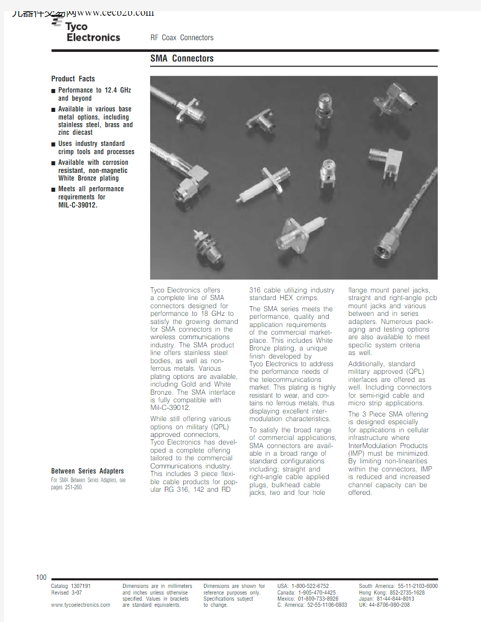
a complete line of SMA connectors designed for performance to 18 GHz to satisfy the growing demand for SMA connectors in the wireless communications industry. The SMA product line offers stainless steel bodies, as well as non-ferrous metals. Various plating options are available, including Gold and White Bronze. The SMA interface is fully compatible with
Mil-C-39012.
While still offering various options on military (QPL) approved connectors,
Tyco Electronics has devel-oped a complete offering tailored to the commercial Communications industry. This includes 3 piece flexi-ble cable products for pop-ular RG 316, 142 and RD 316 cable utilizing industry
standard HEX crimps.
The SMA series meets the
performance, quality and
application requirements
of the commercial market-
place. This includes White
Bronze plating, a unique
finish developed by
Tyco Electronics to address
the performance needs of
the telecommunications
market. This plating is highly
resistant to wear, and con-
tains no ferrous metals, thus
displaying excellent inter-
modulation characteristics.
To satisfy the broad range
of commercial applications,
SMA connectors are avail-
able in a broad range of
standard configurations
including; straight and
right-angle cable applied
plugs, bulkhead cable
jacks, two and four hole
flange mount panel jacks,
straight and right-angle pcb
mount jacks and various
between and in series
adapters. Numerous pack-
aging and testing options
are also available to meet
specific system criteria
as well.
Additionally, standard
military approved (QPL)
interfaces are offered as
well. Including connectors
for semi-rigid cable and
micro strip applications.
The 3 Piece SMA offering
is designed especially
for applications in cellular
infrastructure where
InterModulation Products
(IMP) must be minimized.
By limiting non-linearities
within the connectors, IMP
is reduced and increased
channel capacity can be
offered.
Product Facts
■Performance to 12.4 GHz and beyond
■Available in various base metal options, including stainless steel, brass and zinc diecast
■Uses industry standard crimp tools and processes ■Available with corrosion resistant, non-magnetic White Bronze plating
■Meets all performance requirements for
MIL-C-39012.
Between Series Adapters
For SMA Between Series Adapters, see pages 251-260.
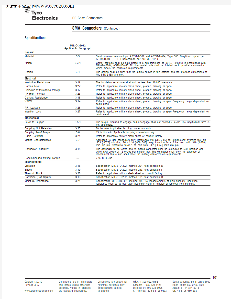
Specifications
MIL-C-39012
Applicable Paragraph
General
Material 3.3Steel corrosion resistant per ASTM-A-582 and ASTM-A-484, Type 303.Beryllium copper per
ASTM-B-196.PTFE Fluorocarbon per ASTM-D-1710.
Finish 3.3.1Center contacts shall be gold plated to a min.thickness of .00127 [.00005] in accordance with
MIL-G-45204, ASTM-B-488.All other metal parts shall be finished as to provide a connector
which meets the corrosion requirements.
Design 3.4The design shall be such that the outline shown in this catalog and the interface dimensions of
MIL-STD-348A are met.
Electrical
Insulation Resistance 3.11The insulation resistance shall not be less than 10,000 megohms.
Corona Level 3.22Refer to applicable military slash sheet, product drawing or spec.
Dielectric Withstanding Voltage 3.17Refer to applicable military slash sheet, product drawing or spec.
RF High Potential 3.23Refer to applicable military slash sheet, product drawing or spec.
Contact Resistance 3.16Refer to applicable military slash sheet, product drawing or spec.
VSWR 3.14Refer to applicable military slash sheet, product drawing or spec.Frequency range dependent on
cable used.
RF Leakage 3.26Refer to applicable military slash sheet, product drawing or spec.
Insertion Loss 3.27Refer to applicable military slash sheet, product drawing or spec.Frequency range dependent on
cable used.
Mechanical
Force to Engage 3.5.1The torque required to engage and disengage shall not exceed 2 in.-lbs.The longitudinal force is
not applicable.
Coupling Nut Retention 3.2560 lbs.min.Applicable for plug connectors only.
Coupling Proof Torque 3.615 in.-lbs.min.Applicable for plug connectors only.
Cable Retention 3.24Refer to applicable military slash sheet or consult factory.
Mating Characteristics 3.7Applicable to jack connectors only.Reference MIL-STD-348A for dimensions;oversize test pin
.953 [.0375] min.dia., .76 - 1.14 [.030-.045] deep, insertion force 3 lbs.max.with .940 [.0370]
min.dia.pin, withdrawal force 1 oz.min.with .902 [.0355] max.dia.pin.
Connector Durability 3.15The connector to be tested and its mating connector shall be subjected to 500 insertion and
withdrawal cycles at 12 cycles per minute max.The connector shall show no evidence of
mechanical failure and shall meet the mating characteristic requirements.
Recommended Mating T orque—7 to 10 in.-lbs.
Environmental
Vibration 3.18Specification MIL-STD-202, method 204, test condition D
Shock 3.19Specification MIL-STD-202, method 213, test condition I
Thermal Shock 3.20Refer to applicable military slash sheet or consult factory.
Corrosion (Salt Spray) 3.13Specification MIL-STD-202, method 101, test condition B.
Moisture Resistance 3.21Specification MIL-STD-202, method 106.No measurements at high humidity.Insulation
resistance shall be at least 200 megohms within 5 minutes of removal from humidity.
Electrical
Contact Resistance Insulation Dielectric Corona RF High Frequency VSWR (milliohms max.)Resistance Withstanding
Extinction RF Potential RF Connector Type Cable
Max.
x (fGHz)Center Outer (megohms Voltage Voltage at Transmission
at 5 MHz Leakage (GHz)Contact Contact min.)(Volts RMS)70,000 Ft.Loss
(V RMS)(dB min.)(V RMS min.)Straight Cable Plug RG 402 (3.58 [.141])
Note 1
1.02 + .005N/A
2.010,000N/A 250N/A 670-(90-fGHz)without Contact
RG 405 (2.16 [.085])18.0 1.05 + .005 2.0
2.010,0001000250.03 √-f(GHz)670-(90-fGHz)RG 402 (
3.58 [.141])18.0 1.05 + .005 2.0 2.010,0001500375.03 √-f(GHz)1000-(90-fGHz)Straight Cable Plugs 3.58 [.141] Microporous 18.0 1.05 + .005 2.0 2.010,0001500375.03 √-f(GHz)1000-(90-fGHz)& Jacks Solder RG 401 (6.35 [.250])18.0 1.07 + .007 2.0 2.010,0001500375.03 √-f(GHz)1000-(90-fGHz)Attachment
RG 174, 188, 316Note 1 1.15 + .01 2.0 2.010,000750190.06 √-f(GHz)500-(60-fGHz)RG 55, 58, 141, 142,
Note 1 1.10 + .005 2.0 2.010,0001000250.06 √-f(GHz)670-(60-fGHz)223, 303, 400Straight Cable Plugs RG 405 (2.16 [.085])12.4 1.10 + .015 2.0 2.010,0001000250.03 √-f(GHz)670-(90-fGHz)& Jacks Solder Clamp Attachment RG 402 (3.58 [.141])
12.4 1.07 + .01 2.0 2.010,0001500375.03 √-f(GHz)1000-(90-fGHz)RG 55, 58, 141, 142
Note 1 1.10 + .005 2.0 2.010,0001000250.06 √-f(GHz)670-(60-fGHz)Straight Cable Plugs 223, 400&Jacks Clamp RG 174, 188, 316Note 1 1.15 + .01
2.0 2.010,000750190.06 √-f(GHz)
500-(60-fGHz)Attachment
RG 180, 195Note 1— 2.0 2.010,000750190—500-(60-fGHz)RG 55, 142, 223, 400Note 1 1.10 + .005 2.0 2.010,0001000250.06 √-f(GHz)670-(60-fGHz)Straight Cable Plugs
RG 58, 141, 303Note 1 1.10 + .005 2.0 2.010,0001000250.06 √-f(GHz)670-(60-fGHz)& Jacks Crimp RG 174, 188, 316Note 1 1.15 + .01
2.0 2.010,000750190.06 √-f(GHz)
500-(60-fGHz)Attachment RG 180, 195
Note 1— 2.0 2.010,000750190—500-(60-fGHz)RG 178, 196Note 1 1.2 + .02 2.0 2.010,000500125.06 √-f(GHz)335-(60-fGHz)Straight Cable Plugs RG 401 (6.35 [.250])
18.0 1.07 + .01 2.0 2.010,0001500375.05 √-f(GHz)1000-70 dB min.& Jacks Compression
6.35 [.250] Microporous 18.0 1.07 + .01 2.0 2.010,0001500375.05 √-f(GHz)1000-70 dB min.Clamp Attachment
6.35 [.250] 3 Spline 18.0 1.07 + .01 2.0 2.010,0001500375.05 √-f(GHz)1000-70 dB min.6.35 [.250] 5 Spline 18.0 1.07 + .01 2.0 2.010,0001500375.05 √-f(GHz)1000-70 dB min.RG 405 (2.16 [.085])12.4 1.18 + .015 2.0 2.010,0001000250.04 √-f(GHz)670-(90-fGHz)RG 405 (2.16 [.085])18.0 1.18 + .015 2.0 2.010,0001000250.04 √-f(GHz)670-(90-fGHz)Right-Angle Cable
RG 402 (3.58 [.141])12.4 1.15 + .015 2.0 2.010,0001500325.04 √-f(GHz)1000-(90-fGHz)Plugs Solder RG 402 (3.58 [.141])18.0 1.10 + .010 2.0 2.010,0001500250.05 √-f(GHz)1000-(90-fGHz)Attachment
RG 55, 58, 141, 142,Note 1 1.15 + .01 2.0 2.010,0001000250.07 √-f(GHz)670-(60-fGHz)223, 303, 400RG 174, 188, 316Note 1 1.15 + .02 2.0 2.010,000750190.07 √-f(GHz)500-(60-fGHz)RG 55, 142, 223, 400Note 1 1.15 + .02 2.0 2.010,0001000250.07 √-f(GHz)670-(60-fGHz)Right-Angle Cable
RG 58, 141, 303Note 1 1.15 + .02 2.0 2.010,0001000250.07 √-f(GHz)670-(60-fGHz)Plugs Crimp RG 174, 188, 316Note 1 1.18 + .02
2.0 2.010,000750190.07 √-f(GHz)
500-(60-fGHz)Attachment RG 180, 195
Note 1— 2.0 2.010,000750190—500-(60-fGHz)RG 178, 196Note 1 1.25 + .025 2.0 2.010,000500125.07 √-f(GHz)335-(60-fGHz)RG 55, 58, 141, 142,
Note 1 1.10 + .005 2.0 2.010,0001000250.08 √-f(GHz)670-(60-fGHz)Right-Angle Cable 223, 303Plugs Clamp
RG 174, 188, 316Note 1 1.15 + .01
2.0 2.010,000750190.08 √-f(GHz)
500-(60-fGHz)Attachment
RG 180, 195Note 1— 2.0 2.010,000750190—500-(60-fGHz)Non-Captured 18.0 1.03 + .004 2.0 2.010,0001000250.03 √-f(GHz)670-(100-fGHz)Flange Mount Plugs
Epoxy Captured 18.0 1.05 + .005 2.0 2.010,0001000250.03 √-f(GHz)670-(60-fGHz)& Jacks Panel or Mechanical Capture 18.0 1.04 + .004 2.0 2.010,0001000250.03 √-f(GHz)670-(100-fGHz)Bulkhead Mount
Field Replaceable 18.0 1.04 + .006 2.0 2.010,0001000250.04 √-f(GHz)670-(100-fGHz)Hermetic Launchers Bulkhead
Epoxy Captured 18.0 1.07 + .010 2.0 2.010,0001000250.04 √-f(GHz)670-(60-fGHz)Feedthrough Jacks Mechanical Capture
18.0 1.07 + .010 2.0 2.010,0001000250.04 √-f(GHz)670-(100-fGHz)Right-Angle Flange
N/A 18.0 1.07 + .015 2.0 2.010,0001000250.08 √-f(GHz)670-(90-fGHz)Mount Jacks N/A 12.4 1.15 + .015
2.0 2.010,0001000250.08 √-f(GHz)
670-(90-fGHz)
Printed Circuit Board
N/A 18.0N/A 2.0 2.010,0001000250N/A 670N/A Mount Straight Terminal
Right-Angle
N/A 12.4N/A 2.0 2.010,0001000250N/A 670N/A Printed Circuit
End Launch
N/A 18.0 1.05 + .005 2.0 2.010,0001000250.03 √-f(GHz)670-(60-fGHz)Stripline Circuit
Surface Launch
N/A 18.0 1.05 + .005 2.0 2.010,0001000250.03 √-f(GHz)670-(60-fGHz)Stripline Circuit
Right-Angle Surface
N/A 12.4 1.15 + .015 2.0 2.010,0001000250.08 √-f(GHz)670-(60-fGHz)Launch Stripline Circuit N/A
18.0
1.07 + .015
2.0
2.0
10,000
1000
250
.08 √-f(GHz)
670
-(60-fGHz)
1.Maximum operating frequency of cable per MIL-C-17.
2.Specifications do not apply to hermetic or compression crimp connectors.
Interface Mating Dimensions
G Dia.
B Dia.
Ref. Plane Note 2
A Dia.
B Dia.A
Dia.
H Dia.
D
E
C
Ref. Plane Note 2
C D
H E
G
F
K
.250-36UNS-2B Thd.
.250-36
UNS-2A Thd.
G Dia.
Plug B
Plug A
Plug
Dimension
Minimum Maximum
A 6.35—.250
B — 4.59.1808
C — 3.43.135
D 0.000.25.000.010
E — 2.54.100
F 0.000.25.000.010
G 0.900.94.0355.037H
0.000.38.000
.015
Jack
Dimension
Minimum Maximum A 5.28 5.49.208.216
B 4.60—.181
C 1.91 1.98.075.078
D 0.000.25.000.010
E 0.38 1.43.015.045
F 2.92—.115
G 0.000.25.000.010
H 4.32—.170J .124 1.30.049.051K
5.54—
.218
Notes:
1.ID to meet VSWR and contact resistance when mated with 0.51 +.025/-.013 [.036 +.0010/-.0005] Dia.Pin.
2.When fully engaged, the two reference planes must coincide with metal to metal contact.
3.Metric equivalents (to the nearest 0.01mm) are given for general information only.
Straight Cable Plug, Solder
Cable Type Body Material Contact Contact Dimension Instruction Part
RG/U& Finish Captivation Attachment A Sheet No.
55, 58, 141, 142, Stainless, Gold
1No Solder
19.7408-48211051638-1
223, 303, 400.775
174, 188, 316Stainless, Gold1No Solder17.5408-47561051644-1
.690
1Coupling nut is passivated stainless steel.
Straight Cable Jack, Solder
Hex.
Cable Type Body Material
Contact Contact Dimension Instruction Part
RG/U& Finish Captivation Attachment A Sheet No.
55, 58, 141, 142, Stainless, Gold No Solder18.5408-48201051852-1
223, 303, 400.730
Bulkhead Cable Jack, Solder
Mounting Hole
6.0
Min.
Cable Type Body Material Contact Contact Dimension Instruction Part
RG/U& Finish Captivation Attachment A Sheet No.
RG 55, 58,Stainless, Gold No Solder24.0408-48171051861-1
141, 142, 300.945
174, 188, 316 Stainless, Gold No Solder21.0408-48171051942-1 Note:Part Numbers are RoHS
compliant except:?Indicates
Right-Angle Cable Plug, Solder
7.9
[.312]Ref.
Cable Type Body Material Contact Contact Dimension
Instruction Part RG/U
& Finish Captivation
Attachment A Sheet No.55, 58, 141, 142, Stainless, Gold 1Y es Solder 16.0408-48161052063-1223, 303, 400.630174, 188, 316
Stainless, Gold 1
Y es
Solder
11.2408-4815
1052067-1
.440
1Coupling nut is passivated stainless steel.
Straight Cable Plug, Clamp
Cable Type Body Material Contact Contact Dimension
Instruction Part RG/U & Finish Captivation
Attachment
A Sheet No.174, 188, 316
Stainless, Pass.
Y es
Solder
2.9408-4906
1050721-1
.116
Straight Cable Jack, Clamp
Cable Type Body Material Contact Contact Dimension
Instruction Part RG/U & Finish
Captivation
Attachment A Sheet No.174, 188, 316
Stainless, Pass.
Y es
Solder
2.9408-4906
1050903-1
.116
Bulkhead Feedthrough Cable Jack, Clamp
Cable Type Body Material Contact Contact Instruction Part RG/U
& Finish Captivation
Attachment Sheet No.174, 188, 316 Stainless, Pass.Y es
Solder
408-4704
1050996-1
Ref.
Mounting Hole
6.0
Min.
Right-Angle Cable Plug, Clamp
Cable Type
Body Material Contact Contact Instruction Part RG/U
& Finish Captivation Attachment Sheet No.174, 188, 316 Stainless, Pass.Mechanical Solder 408-4965
1051140-1
Max.
Ref. Plane
Straight Cable Plug, Crimp
Cable Type Body Material Contact Contact Crimp Instruction Part RG/U & Finish Captivation Attachment Tooling Sheet No.Part No.174, 179, 187, Stainless, Pass.Mechanical Solder/Crimp 21055236-1408-46611056443-1188, 316RD316
Stainless, Pass.Mechanical Solder/Crimp 21055236-11408-46611056436-155, 142, 223, 400Stainless, Pass.
Mechanical Solder/Crimp 21055236-1408-46611056438-1174, 179, 187,Brass,Mechanical
Solder/Crimp 2
1055236-1
408-4661
1082034-1
188, 316
White Bronze
1Use die 1055270-1 to crimp RD316 ferrule.2Use die 1055880-1 to crimp center contact.
Straight Cable Jack, Crimp
27.43
Cable Type Body Material Contact Contact Crimp Instruction Part RG/U & Finish Captivation Attachment Tooling Sheet Style No.Part No.
174, 316Brass, Nickel Mechanical Solder 1
408-4032A 5447648-358, 141, 303 Stainless, Pass.Mechanical Solder 1055236-1408-4704B 1051867-1174, 188, 316 Stainless, Pass.Mechanical Solder 1055236-1408-4708B 1051855-1178, 196 Stainless, Pass.
Mechanical
Solder
1055236-1
408-4806
B
1051869-1
1Refer to T
yco Electronics Customer Print for tooling requirement.
DANIELS Mil Tooling used for contact and ferrule
crimp.
Bulkhead Feedthrough Cable Jack, Crimp
6.0[.235]
Recommended Mounting Hole
Cable Type Body Material Contact Contact Crimp Instruction Part RG/U & Finish Captivation Attachment Tooling Sheet No.Part No.174, 179, 187, Stainless, Pass.Mechanical Solder/Crimp 21055236-1408-46611056452-1188, 316RD316Stainless, Pass.Mechanical Solder/Crimp 21055236-13408-46611056445-158, 141, 303Stainless, Pass.Mechanical Solder/Crimp 21055236-1408-46611056450-155, 142, Stainless, Pass.Mechanical Solder/Crimp 2
1055236-1
408-46611056447-1223, 400174, 188, 316
Brass, Nickel
Mechanical
Crimp
1
408-4032
5448103-2
1Refer to T yco Electronics Customer Print for tooling requirement.DANIELS Mil Tooling used for contact and ferrule
crimp.
2Use die 1055880-1 to crimp center contact.3Use die 1055270-1 to crimp RD316 ferrule.
Style A
Style B
DANIELS is a trademark of Daniels
Right-Angle Cable Plug,Crimp
7.9
[.312]Cable Type Body Material Contact Contact Crimp
Instruction
Part RG/U & Finish Captivation Attachment Tooling Sheet No.Part No.
174, 179, 187, Stainless, Pass.Mechanical Solder 1055236-1408-46591056462-1188, 31658, 141, 303
Stainless, Pass.
Mechanical
Solder
1055236-1
408-4659
1056456-1
Right-Angle Cable Plug,
Crimp
Ref.
7.9
[.312]
13.4
[.530]
Cable Type Body Material Contact Contact Crimp Instruction Part RG/U & Finish Captivation Attachment Tooling Sheet No.Part No.55, 142, Stainless, Pass.Epoxy Solder 1055236-1408-46811052072-1223, 400174, 188, 316Stainless, Pass.Epoxy Solder 1055236-1408-46831052076-1178, 196
Stainless, Pass.
Epoxy
Solder
1055236-1
408-4801
1052098-1
Straight Push-On
6.35
Min.
Ref.
± 0.13
± .005]
6.35
Min.
± 0.13
± .005] Right-Angle Push-On
Cable Type Body Material Contact Contact Part
RG/U& Finish Captivation Attachment No.
316Beryllium Copper, Gold Mechanical Solder/Crimp1274694-1
Cable Type Body Material Contact Contact Part
RG/U& Finish Captivation Attachment No.
316Beryllium Copper, Gold Mechanical Crimp1408541-1
Straight Cable Plug
8.40
5.4[.213]
Cable Type Body Material Contact Contact Solder Instruction Part RG/U & Finish Captivation Attachment Assembly Kit Sheet No.Part No.402 (3.58 [.141])
Stainless, Pass.
No Center No Center 1055420-1
408-4761
1050757-1
Contact
Contact
Straight Cable Plug
8.1[.320]
Ref.
Cable Type Body Material Contact Contact Solder Instruction
Part RG/U & Finish Captivation Attachment
Assembly Kit Sheet No.Part No.
402 (3.58 [.141])Stainless, Gold 1No Solder 1055420-1408-47641050525-1405 (2.16 [.085])Stainless, Gold 1No Solder 1055420-1408-4765
1050770-1402 (3.58 [.141])Stainless, Gold 1No Center No Center
N/A
—1050542-1Contact Contact 405 (2.16 [.085])
Stainless, Gold 1
No
Solder 1055420-1
—
1050548-1
1Coupling nut is passivated stainless steel.
Straight Cable Jack
[.144] RG402/U [.089] RG405/U
Cable Type Body Material Contact Contact Solder Instruction Part RG/U & Finish Captivation
Attachment Assembly Kit Sheet No.Part No.402 (3.58 [.141])Stainless, Gold No Solder 1055420-1408-47671050854-1405 (2.16 [.085])
Stainless, Gold
No
Solder
1055420-1
408-4833
1050859-1
Bulkhead Cable Jack
6.0
Min.Cable Type Body Material Contact Contact Solder Instruction Part RG/U & Finish Captivation
Attachment Assembly Kit Sheet No.Part No.
402 (3.58 [.141])
Brass, Gold
No
Solder
1055420-1
408-4768
1082029-1
2 Hole Flange Mount Cable Jack
7.6[.299]
Ref.Cable Type Body Material Contact Contact Solder Instruction Part RG/U & Finish Captivation
Attachment Assembly Kit Sheet No.Part No.402 (3.58 [.141])Stainless, Gold No Solder
1055420-1408-47671051052-1405 (2.16 [.085])
Stainless, Gold
No
Solder
1055420-1
408-4883
1051046-1
4 Hole Flange Mount Cable Jack
7.6
[.299]
? 3.66 [.144] RG402/U ? 2.26 4 Plcs.2 Plcs.Cable Type Body Material Contact Contact Solder Instruction Part RG/U & Finish Captivation
Attachment Assembly Kit Sheet No.Part No.402 (3.58 [.141])Stainless, Gold No Solder 1055420-1408-47671051081-1405 (2.16 [.085])
Stainless, Gold
No
Solder
1055420-1
408-4883
1051085-1
Right-Angle Cable Plug, Direct Solder Attachment
Ref. Plane
Ref.
Ref.
[.144] RG402/U [.089] RG405/U
Cable Type Body Material Contact Contact Solder Instruction
Part RG/U & Finish Captivation Attachment
Assembly Kit Sheet No.
Part No.
402 (3.58 [.141])Stainless, Gold 1
Epoxy Solder 1055420-1408-48311051151-1405 (2.16 [.085])Stainless, Gold 1Epoxy Solder 1055420-1408-48311051157-1405 (2.16 [.085])
Brass, Gold
Mechanical
Solder 1055420-1
408-4831
1088312-1
1Coupling nut is passivated stainless steel.
Straight Cable Plug, Crimp
6.9 [.270] RG402/U
7.1 [.278] RG405/U
[.143] RG402/U [.089] RG405/U
Ref Cable Type Body Material Contact Contact Crimp
Instruction
Part RG/U & Finish Captivation Attachment Tooling Sheet No.Part No.405 (2.16 [.085])Stainless, Pass.Mechanical Solderless
1055835-1
408-46951050598-1402 (3.58 [.141])
Stainless, Pass.
No Center Contact
Solderless 1055835-1
408-4690
1050740-1
Straight Cable Plug —
Low Profile, Crimp
5.8[.229]
8.6[.337]
Cable Type Body Material Contact Contact Crimp Instruction Part RG/U & Finish Captivation Attachment Tooling Sheet No.Part No.402 (3.58 [.141])Stainless, Pass.Mechanical Solderless 1055835-1408-46961050602-1405 (2.16 [.085])
Stainless, Pass.
Mechanical
Solderless
1055835-1
408-4697
1050611-1
2 Hole Flange, Crimp
7.90
[.312]
Hex.Cable Type Body Material Contact Contact Crimp Instruction Part RG/U & Finish Captivation Attachment Tooling Sheet No.Part No.402 (3.58 [.141])Stainless, Pass.
Mechanical Solderless 1055835-1408-49541051005-1405 (2.16 [.085])
Stainless, Pass.
Mechanical
Solderless
1055835-1
408-4689
1051007-1
Right-Angle Cable Plug, Crimp
? 3.63 ? 2.26 After Crimping
Ref. After Crimping
Cable Type Body Material Contact Contact Crimp Instruction Part RG/U & Finish Captivation Attachment Tooling Sheet No.Part No.402 (3.58 [.141])Stainless, Pass.Mechanical Solderless 1055835-1408-46911051145-1405 (2.16 [.085])
Stainless, Pass.
Mechanical
Solderless
1055835-1
408-4692
1051147-1
Recommended Mounting Hole
2 Hole Flange Mount Jack
Receptacle
9.5 1.7[.065]
5.7
[.223]
12.2[.481]
Typ.[.050]
0.8[.031]Dia.Min.
Dia.
2.6Dia.Body Material Contact RF Leakage Temperature Part & Finish
Captivation db min.Range No.Stainless, Passivated Epoxy
-(60-fGHz)-65 to 125°C 1052544-1
2 Hole Flange Mount Jack Receptacle
Body Material Contact RF Leakage Temperature Part & Finish
Captivation db min.Range No.
4 Hole Flange Mount Plug
Receptacle
12.9
[.507]
Ref.[.050]
Dia.7.9
Hex Dia.4 Plcs.
Body Material Contact RF Leakage Temperature Part & Finish
Captivation db min.Range No.Stainless, Passivated Epoxy N/A -65 to 125°C 1052324-1
4 Hole Flange Mount Jack Receptacle
4 Plcs.Ref. Plane
8.6
Typ.Body Material Contact RF Leakage Temperature Part & Finish
Captivation db min.Range No.Stainless, Passivated Epoxy
-(60-fGHz)-65 to 125°C 1052422-1
Note:Part Numbers are RoHS
compliant except:?Indicates
Bulkhead Feedthrough Jack
Receptacle, Solder Pot Terminal
6.0
1.37.9
[.312]
Recommended Mounting Hole
Min.Dia.Body Material Contact RF Leakage Temperature Part & Finish
Captivation db min.Range No.Stainless, Passivated
Epoxy
N/A -65 to 125°C 1053092-1
Press-In Cable,Jack Panel
– .001Cable Type Body Material Contact Temperature RG/U & Finish Captivation Range Part No.316 D Brass, Gold Mechanical –65 to 125°C
619115-1
Press-In Jacks,
Straight Terminal
+ 0.03– 0.07+ .001
? 0.50[.020]
Part Number 1460468
4.50 ±[.177 ±+ 0.10– 0.20+ .004
– .008[.315]
+ 0.403.50Part Number 1460469
Body Material
Contact RF Leakage Temperature Part & Finish
Captivation db min.Range No.Brass, White Bronze
Mechanical N/A –65 to 125°C 1460468-1Brass, Gold
Mechanical
N/A
–65 to 125°C
1460469-1
Note:Part Numbers are RoHS
compliant except:?Indicates
4 Hole Flange Mount Jack
Receptacle
Typ.4 Plcs.Body Material Contact RF Leakage Temperature Part & Finish
Captivation db min.Range No.Stainless, Passivated None -(100-fGHz)-65 to 165°C 1052518-1Stainless, Passivated Epoxy -(60-fGHz)-65 to 125°C 1052523-1Stainless, Gold Epoxy -(60-fGHz)-65 to 125°
C
1052522-1
2 Hole Flange Mount Plug Receptacle
25.3
1.7Body Material Contact RF Leakage Temperature Part & Finish
Captivation db min.Range No.Stainless, Passivated Epoxy -(60-fGHz)-65 to 125°C 1052349-1
2 Hole Flange Mount Jack Receptacle
.250-36 UNS-2A
Body Material Contact RF Leakage Temperature Part & Finish
Captivation db min.Range No.Stainless, Passivated Epoxy -(60-fGHz)-65 to 125°C 1052552-1
Bulkhead Feedthrough Jack Receptacle
Body Material Contact RF Leakage Temperature Part & Finish
Captivation db min.Range No.Stainless, Passivated Epoxy -(60-fGHz)-65 to 125°C 1053222-1
2 Hole Flange Mount Right-Angle Jack Receptacle
Body Material Contact RF Leakage Temperature
Part & Finish
Captivation db min.Range No.Stainless, Passivated Mechanical -(90-fGHz)-65 to 165°C 1052986-1
4 Hole Flange Mount Right-Angle Jack Receptacle
Body Material Contact RF Leakage Temperature Part & Finish
Captivation db min.Range No.Stainless, Passivated Mechanical -(90-fGHz)-65 to 165°C 1052978-1Stainless, Passivated Mechanical -(90-fGHz)-65 to 165°C 1052982-1
4 Hole Flange Mount Jack Receptacle, Straight Terminal
4 Plcs.8.6
Typ.
1.7
Body Material Contact Slot Width RF Leakage Temperature Part & Finish Captivation +.076/-.025
db min.Range No.[+.003/-.001]Stainless, Passivated
Epoxy
0.5 [.018]
-(60-fGHz)
-65 to 125°C
1052563-1
4 Hole Flange Mount Plug Receptacle, Tab Terminal
4 Plcs.8.6
0.1
X
Thk.1.2Wide Tab
Typ.
Body Material Contact Tab RF Leakage Temperature Part & Finish
Captivation Width db min.Range No.
Stainless, Passivated Epoxy 1.3 [.050]-(60-fGHz)-65 to 125°C 1052360-1
4 Hole Flange Mount Jack Receptacle, Tab Terminal
7.6
[.299]
8.6
? 2.6 4 Plcs.2 Plcs.Body Material Contact Tab RF Leakage Temperature Part & Finish
Captivation Width db min.Range No.Stainless, Passivated Epoxy .51 [.020]-(60-fGHz)-65 to 125°C 1052898-1
2 Hole Flange Mount Jack Receptacle, Panel Mount,
Tab Terminal
2 Plcs.
Body Material Contact Horizontal RF Leakage Temperature Part & Finish
Captivation Tab db min.Range No.Stainless, Passivated
Epoxy ?-(60-fGHz)-65 to 125°C 1052577-1
4 Hole Flange Mount Jack Receptacle, for Microstrip Transmission Line Circuits
Typ.
4 Plcs.Body Material Contact RF Leakage Temperature Part & Finish
Captivation db min.Range No.Stainless, Passivated Epoxy -(60-fGHz)-65 to 125°C 1052528-1
2 Hole Flange Mount Jack Receptacle, for Microstrip Transmission Line Circuits
Body Material Contact RF Leakage Temperature Part & Finish
Captivation db min.Range No.Stainless, Passivated Epoxy -(60-fGHz)-65 to 125°C 1052902-1