SB330-B中文资料
e 3
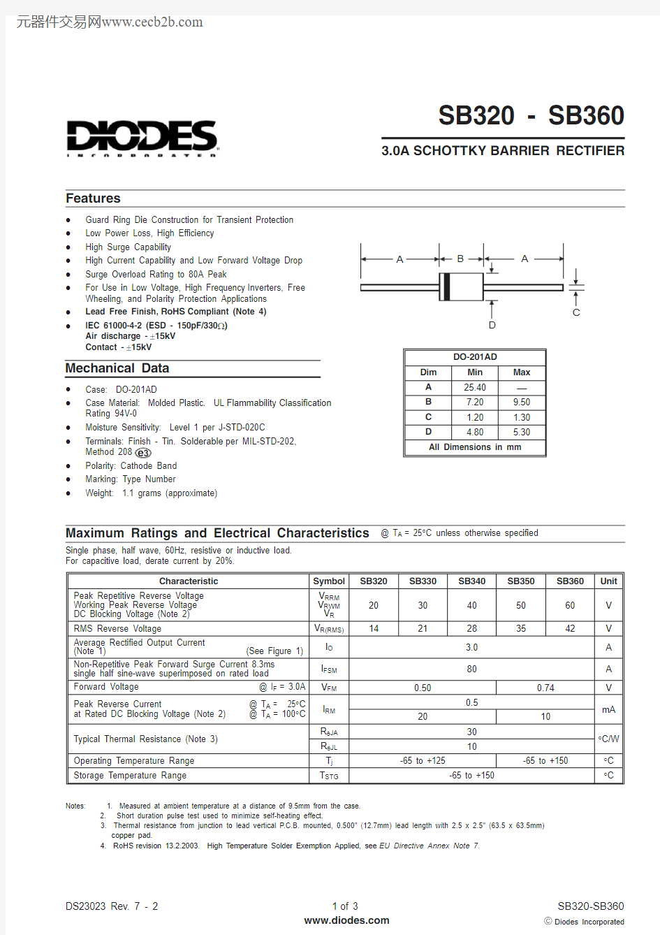
SB320 - SB360
3.0A SCHOTTKY BARRIER RECTIFIER
Features
Maximum Ratings and Electrical Characteristics
@ T A = 25°C unless otherwise specified
·Guard Ring Die Construction for Transient Protection ·Low Power Loss, High Efficiency ·High Surge Capability
·High Current Capability and Low Forward Voltage Drop ·Surge Overload Rating to 80A Peak
·For Use in Low Voltage, High Frequency Inverters, Free Wheeling, and Polarity Protection Applications ·Lead Free Finish,RoHS Compliant (Note 4)·
IEC 61000-4-2 (ESD - 150pF/330W )Air discharge -±15kV Contact -±15kV
Mechanical Data
·Case: DO-201AD
·Case Material: Molded Plastic. UL Flammability Classification Rating 94V-0
·Moisture Sensitivity: Level 1 per J-STD-020C ·Terminals: Finish - Tin.Solderable per MIL-STD-202,Method 208·Polarity: Cathode Band ·Marking: Type Number
·
Weight: 1.1 grams (approximate)
Single phase, half wave, 60Hz, resistive or inductive load.For capacitive load, derate current by 20%.
Notes: 1. Measured at ambient temperature at a distance of 9.5mm from the case.
2. Short duration pulse test used to minimize self-heating effect.
3. Thermal resistance from junction to lead vertical P.C.B. mounted, 0.500" (12.7mm) lead length with 2.5 x 2.5" (63.5 x 63.5mm)copper pad.
4.RoHS revision 13.2.2003. High Temperature Solder Exemption Applied, see EU Directive Annex Note 7.
016
32
48
64
80
1
10
100
I ,P E A K F O R W A R D S U R G E C U R R E N T (A )
F S M NUMBER OF CYCLES AT 60Hz
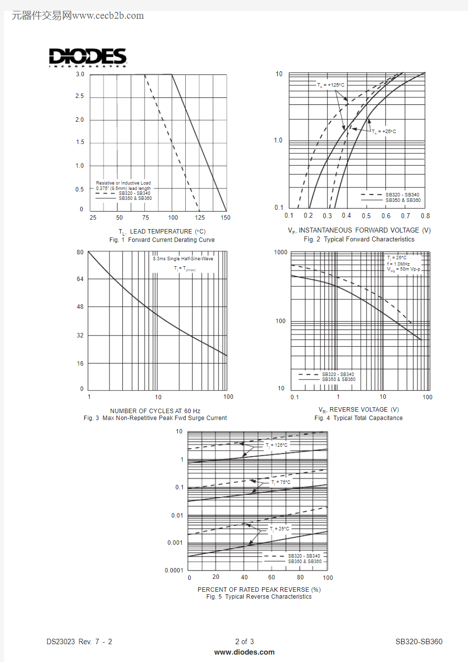
Fig.3Max Non-Repetitive Peak Fwd Surge Current
10
100
1000
0.1
1
10
100
C ,T O T A L C A P A C I T A N C E (p F )
T V ,REVERSE VOLTAGE (V)Fig.4Typical Total Capacitance
R
0.01
0.1
1
10
0.001
0.0001
20
40
60
80
100
I ,I N S T A N T A N E O U S R E V E R S E C U R R E N T (m A )
R PERCENT OF RATED PEAK REVERSE (%)Fig.5Typical Reverse Characteristics
0.1
1.0
10
0.1
0.3
0.4
0.2
0.5
0.6
0.7
0.8
I ,I N S T A N T A N E O U S F O R W A R D C U R R E N T (A )
F V ,INSTANTANEOUS FORWARD VOLTAGE (V)
Fig.2Typical
Forward Characteristics
F 0
0.51.0
255075100125150
I A V E R A G E F O R W A R D C U R R E N T (A )
O ,T ,
LEAD
TEMPERATURE (C)Fig.1Forward Current Derating Curve
L °1.5
2.0
2.5
3.0
Notes:
5.For packaging details, visit our website at https://www.360docs.net/doc/3017830720.html,/datasheets/ap02008.pdf
(Note 5)
Ordering Information
IMPORTANT NOTICE
LIFE SUPPORT
Diodes Incorporated and its subsidiaries reserve the right to make modifications,enhancements,improvements,corrections or other changes without further notice to any product herein.Diodes Incorporated does not assume any liability arising out of the application or use of any product described herein;neither does it convey any license under its patent rights,nor the rights of others.The user of products in such applications shall assume all risks of such use and will agree to hold Diodes Incorporated and all the companies whose products are represented on our website,harmless against all damages.
Diodes Incorporated products are not authorized for use as critical components in life support devices or systems without the expressed written approval of the President of Diodes Incorporated.