IRPLLNR5;中文规格书,Datasheet资料
IRPLLNR5
IRPLLNR5 Wide Range Input Linear Fluorescent Ballast Reference Design Using the IRS2168D
Table of Contents
Page
1. Features (2)
2. Description (2)
3. Electrical Characteristics (3)
4. Fault Protection Characteristics (4)
5. IRPLLNR5 Schematics (5)
6. PCB Component Placement Diagram and Board Fabrication (6)
7. Bill of Material and Inductor Specification (8)
8. Functional Description (11)
1.Features
?Drives 1 x 54 W TL5 Lamp
?Input Voltage: 90-305 VAC
?High Power Factor/Low Total Harmonic Distortion
?High Frequency Operation
?Lamp Filament Preheating
?Lamp Fault Protection with Auto-Restart After Lamp Replacement
?Low AC Line Protection
?Lamp End-of-Life Shutdown
?IRS2168D HVIC Ballast Controller
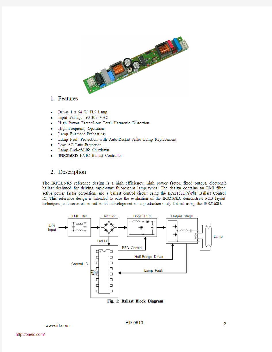
2.Description
The IRPLLNR5 reference design is a high efficiency, high power factor, fixed output, electronic ballast designed for driving rapid-start fluorescent lamp types. The design contains an EMI filter, active power factor correction, and a ballast control circuit using the IRS2168D(S)PbF Ballast Control IC. This reference design is intended to ease the evaluation of the IRS2168D, demonstrate PCB layout techniques, and serve as an aid in the development of a production-ready ballast using the IRS2168D.
Line
Input
Lamp
3.Electrical Characteristics
Parameter Units Value Lamp Type 54 W TL5 Input Power [W] 54 Lamp Running Voltage [Vpp] 400 Run Mode Frequency [kHz] 50 Preheat Mode Frequency [kHz] 85 Preheat Time [s] 1.0 Lamp Preheat Voltage [Vpp] 500 Lamp Ignition Voltage [kVpp] 2.0 Input AC Voltage Range [VAC] 90-305 VAC
Power Factor 0.995 at 120 VAC 0.98 at 220 VAC
Total Harmonic Distortion [%] 10 at 120 VAC 14 at 220 VAC
Table 3.1: Ballast Parameters
Vin Pin (W) PF THD (%)DCBUS (V)
90 55.5 0.997 9.15 495 110 52.8 0.996 9.85 495 130 51.8 0.994 11 495 150 51.1 0.992 11.25 495 170 50.8 0.99 12.2 495 190 50.7 0.987 12.8 495 210 50.6 0.983 13.9 495 230 50.5 0.978 14.9 495 250 50.5 0.972 16.1 495 270 50.5 0.964 17.7 495
Table 3.2: PFC Data
Fig. 2: PFC and THD Performances versus Input Voltage
4.Fault Protection Characteristics
Operation Fault Ballast Restart Line Voltage Low Deactivates Increase line voltage
Upper Filament Broken Deactivates Lamp exchange
Lower Filament Broken Deactivates Lamp
exchange Failure to Ignite Deactivates Lamp exchange
exchange Open Circuit (no lamp) Deactivates Lamp
End of Life Deactivates Lamp exchange
5.IRPLLNR5 Schematics
Fig. 3: Schematic Diagram, IRS2168D, Single Lamp, Voltage Mode Heating
6.PCB Component Placement Diagram and Board Fabrication
Fig. 4: PCB Component Placement Diagram
Board Fabrication
1)Board size: L = 8.59 inch, W = 1.195 inch
2)No. of copper layers: 1 (bottom layer)
oz.
3)Copper:
2
FR-4
4)Board
material:
5)Through hole plating: No
6)Solder plating on pads: Yes
7)Solder mask: Green LP1 (bottom layer only)
8)Silk screen layers: Top and bottom
9)Silk screen ink: White epoxy, non-conductive
file: IRPLLNR5.ZIP
10)Gerber
11)Gerber file description:
a)IRPLLNR5.apr Apertures
b)IRPLLNR5.DRL NC drill
c)IRPLLNR5.DRR NC drill
d)IRPLLNR5.GBL Bottom layer
e)IRPLLNR5.GBO Silk screen bottom
f)IRPLLNR5.GBS Solder mask bottom
g)IRPLLNR5.GD1 Drill drawing
h)IRPLLNR5.GG1 Drill guide
i)IRPLLNR5.GM1 Mechanical layer
j)IRPLLNR5.GTO Silk-screen top
7. Bill of Material and Inductor Specification
Item Qty Manufacturer Part Number Description
Reference
1
1
Diodes Inc.
DF10S
Bridge Rectifier, 1 A, 1000 V BR1 2 1 Roederstein WKP222MCPEJ0K Capacitor, 2.2 nF, 305 VAC Y Cap CY 3 1 Dale CW-1/2 Resistor, 0.5 ?, 1/2 W F1 4 1 Roederstein F1772433-2200 Capacitor, 0.33 μF, 275 VAC C1 5 1 Panasonic ELF-15N007A EMI Inductor, 10 mH, 0.7 A peak L1 6 1 Vishay Dale MKP1841410634 Capacitor, 0.1 μF, 630 VDC C2 7
1
Wima
MKP10-.1/400/10 Capacitor, 0.1 μF, 400 VDC CDC 8 1 Panasonic ERZ-V05D471 Transient Suppressor RV1 9 1 VOGT
IL 060 320 41 02 PFC Inductor, 2 mH, 2.5 A peak LPFC
10 2 Panasonic EEU-EB2V330S Capacitor, 33 μF, 350 VDC, 105 °C CBUS1, CBUS2 11 2 Panasonic ECJ-3VB1E104K Capacitor, 0.1 μF, SMT 1206 CBS, CVCC
12 2 Panasonic ECU-V1H102JCH Capacitor, 1 nF, SMT 1206 CSD, CEOL (see Note 2) 13 3 Panasonic ECJ-3YB1E105K Capacitor, 1 μF, SMT 1206 CCOMP, CPH, CVCO 14 1 Panasonic ECU-V1H103KBM Capacitor, 0.01 μF, SMT 1206 CVBUS 15 1 Panasonic
ECJ-3VB1E334K Capacitor, 0.33 μF, SMT 1206 CSD1 16 1 Panasonic
ECE-A1EKG100 Capacitor, 10 μF, 25 VDC, 105 °C CVCC1 17 1 Johanson Dielectrics 102R29W102KV4E Capacitor, 1 nF, 1 kV, SMT 1808 CBS 18 1 WIMA FKP1-3300/2000/5 Capacitor, 3.3 nF, 2 kV CRES 19 2 Panasonic ECU-V1H471KBM Capacitor, 470 pF, SMT 1206 CCS, COC 20 2 Panasonic ECQB1104JFW Capacitor, 0.1 μF, 100 V
CH1, CH2 21 1 Diodes Inc. ZMM5240B-7 Zener diode, 10 V, Minimelf, 0.5 W DEOL1 22 1 Diodes Inc. ZMM5232B-7 Zener diode, 5.6 V, Minimelf, 0.5 W DEOL2 23 1 Digi-key MURS160DICT-ND Diode, 1 A, 600 V, SMT SMB DPFC
24 3 Diodes
LL4148DICT-ND Diode, 1N4148, SMT DL35 DCP1, DCP2, DSD 25 1 Tyco Electronics/Amp 2-641262-1 DIP 16 IC Socket Through-Hole IC1 26 1 International Rectifier IRS2168D IC, Ballast Driver / PFC
IC1 27 1 VOGT IL 060 320 51 01 Resonant Inductor, 2 mH, 2 A peak LRES
28 3 International Rectifier IRFB9N60A Transistor, MOSFET MPFC, MHS, MLS 29
2
> = 22 A.W.G
Jumpers
J1, J2
30 5 Panasonic ERJ-8GEYJ120V Resistor, 12 ?, SMT 1206 RPFC, RLO, RHO, RLM1, RLM2 31 1 Panasonic
ERJ-8GEYJ474V Resistor, 470 k ?, SMT1206 RCPH 32 1
Phoenix Passive
Components 5033ED220K0F12AF5 Resistor, 220 k ?, 1/2 W RVCC
33 2 Panasonic ERJ-8GEYJ684V Resistor, 680 k ?, SMT 1206 RVBUS1, RVBUS2 34 1 Panasonic ERJ-8GEYJ333V Resistor, 33 k ?, SMT 1206 RZX 35
2
Panasonic
ERJ-8GEYJ102V
Resistor, 1 k ?, SMT 1206
RF1, RF2 36 1 Vishay/Dale RS01A1R500FS70 Resistor, 1.5 ?, 1%, 1 W RCS 37 1 Digi-Key P0.62W-1BK-ND Resistor, 0.62 ?, 1 W
ROC 38 1 Panasonic ERJ-8ENF1132V Resistor, 11.3 k ?, 1%, SMT 1206 RVBUS 39 1 Panasonic ERJ-8GEYJ104V Resistor, 100 k ?, SMT 1206 RSD
40 4 Panasonic ERJ-8GEYJ224V Resistor, 220 k ?, SMT 1206 REOL1, REOL2, REOL3, RPU 41 1 Panasonic ERJ-8GEYJ203V Resistor, 20 k ?, 5%, SMT 1206 REOL4 (see Note 3) 42 1 Digi-key 36.0KFRCT-ND Resistor, 36 k ?, 1%, SMT 1206 RFMIN 43
1
Panasonic
ERJ-8GEYJ563V Resistor, 56 k ?, 1%, SMT 1206 RPH 44 1 WAGO 235-203 Connector, 3 terminal X1 45 1 WAGO
235-207
Connector, 4 terminal
X2
Table 1: Bill of Material
Lamp type: 54 W TL5; Line Input Voltage: 80-305 VAC
Note 1: Different lamp types require different frequency programming components.
Note 2: CEOL and CSD values can be increased up to 470 nF to increase noise immunity. Note 3: REOL4 value can be increased to 33 k? for a more sensitive lamp end-of-life detection
Fig. 5: Power Factor Inductor Specification
Fig. 6: Resonant Inductor Specification
分销商库存信息: IR
IRPLLNR5