Phase composition and solid solution strengthening effect in TiZrNbMoV
Phase composition and solid solution strengthening effect in TiZrNbMoV high-entropy
alloys
Y.D.Wu,Y.H.Cai,X.H.Chen,T.Wang,J.J.Si,L.Wang,Y.D.Wang,X.D.Hui ?
State Key Laboratory for Advanced Metals and Materials,University of Science and Technology Beijing,Beijing 100083,PR China
a r t i c l e i n f o Article history:
Received 9May 2015Accepted 7June 2015
Available online 19June 2015Keywords:
High-entropy alloys TiZrNbMoV
Phase composition Solid solution phase Compressive properties
a b s t r a c t
TiZrNbMo x V y high-entropy alloys (HEAs)with x =0–2,y =1and y =0.3,respectively,were designed and prepared by copper mold casting technology.The phase composition and stability of these HEAs were investigated.It is shown that the HEAs with low content of V are composed of only one type of bcc solid solution phase (SSP),and demonstrate excellent phase stability at 1273K.The high content of V and Mo results in the formation of two types of bcc SSPs and the decrease of phase stability in the HEAs.Based on the previously proposed criteria,the formation ability of solid solution phase for this kind of HEAs was comprehensively evaluated.The compressive mechanical properties of the as-cast and annealed HEAs were measured.It has been found that Mo plays a strong solid solution strengthening effect on this kind of HEAs.Especially,TiZrNbMo 0.3V 0.3has the yield strength and plastic strain of 1312MPa and >50%,respectively,and still maintains the excellent plastic deformation ability even after annealed at 1273K for 72h.The strengthening effect in this kind of HEAs is considered to be due to the shear modulus mis-match.The solubility limit of HEAs is correspondent to shear modulus mismatch of 29.
ó2015Elsevier Ltd.All rights reserved.
1.Introduction
Historically,metallic materials have being principally designed in the way that an alloy has one or two kinds of predominant ele-ments,and all the other elements in this alloy only play an ancil-lary role.In recent years,this dogma in the composition design of metallic materials has been broken by a subversive concept named as ‘‘high-entropy’’.The high-entropy alloys (HEAs)were designed according to the principle of equal-molar or near-equalmolar fraction for all the components,which then results in a high con?gurational entropy in the alloy [1,2].The high-entropy is bene?cial to the stabilization of disordered solid solution phases such as a body-or face-centered cubic (fcc),and disadvantageous to the formation of ordered intermetallic crys-talline phases.Nevertheless,it is noticed that the con?gurational entropy only takes into account of a part of the entire entropy for a certain alloy.This means that only a few of,but not all the alloy system can form single solid solution phase such as face-centered cubic (fcc)[3–5],body-centered cubic (bcc)[6–9],and orthorhombic [10]phase.
HEAs have attracted great attraction due to their high strength and ductility,excellent oxidation resistance and thermal stability,etc.[2,11,12,37–40].Of the HEAs discovered to date,bcc type of HEAs exhibit enhanced strength and excellent phase stability at high temperature.For instance,the tensile strengths of FeCoCrNiMn HEAs are under 600MPa [13,14]when they have fcc type of structure.As Al element is added into FeCoCrNiMn HEAs,the tensile strength can be increased up to 1150MPa [14]due to the formation of bcc type of crystalline structure.For high temper-ature applications,Senkov et al.developed refractory NbMoTaWV and TaNbHfZrTi HEAs [6,7],which have bcc type of structure and demonstrate high temperature strength and excellent phase stabil-ity at 1473K.However,it is seen that these HEAs still have the de?ciencies of high cost and density due to the existence of Hf and Ta elements.In order to decrease the density and further improve the oxidation resistance of refractory HEA,Senkov et al.investigated the CrNbTiVZr HEAs [36].They found that the Cr bear-ing HEAs contain a lot of Laves phases and exhibit great brittleness at room temperature.Therefore,it is signi?cant to explore new refractory HEAs with low cost,low density and high ductility.Alternatively,TiZrNbMoV HEAs are promising for high tempera-ture engineering and manufacture industries considering that they are cheaper and lighter than NbMoTaW HEAs.As for TiZrNbMoV HEAs,Tian et al.studied the equilibrium bulk properties of TiZrNbMoV HEAs by using ab initio method [15].Zhang et al.inves-tigated the effect of V on the phase formation and mechanical properties [16].It has been shown that the alloying effect of V ele-ment in this kind of HEAs can be negligible.
https://www.360docs.net/doc/488438600.html,/10.1016/j.matdes.2015.06.072
0264-1275/ó2015Elsevier Ltd.All rights reserved.
?Corresponding author.
E-mail address:xdhui@https://www.360docs.net/doc/488438600.html, (X.D.Hui).
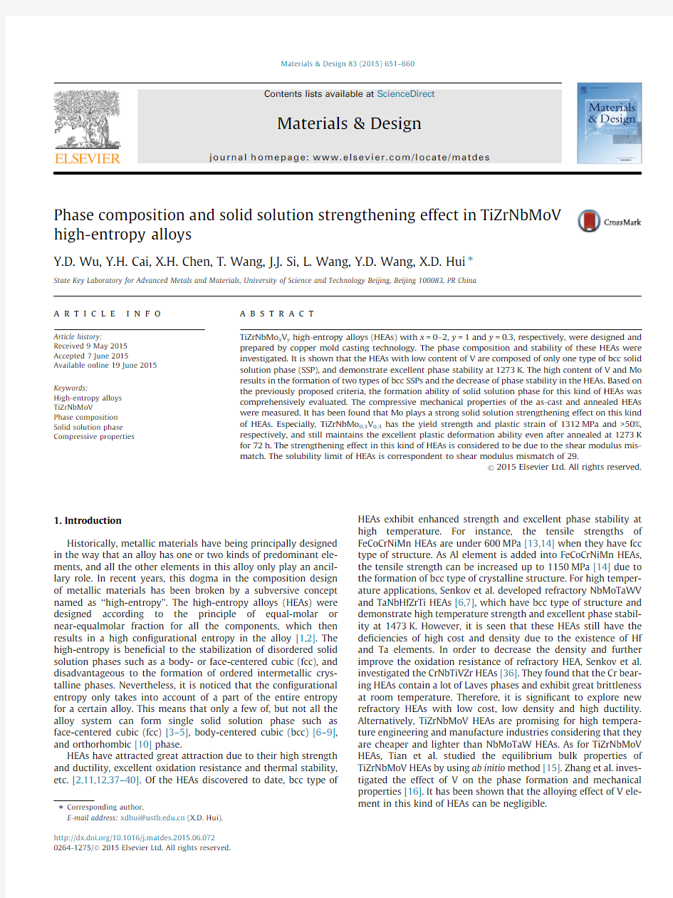
Fig.1.(a)and(c)The XRD patterns of G-MV10and G-MV3HEAs,(b)and(d)the magni?ed(110)peaks as shown in(a)and(c),respectively.
2.The SEM backscattering electron micrographs of as-cast(a)M0V10,(b)M3V10,(c)M13V10and(d)M17V10alloy.
Table1
The chemical composition in different region of TiZrNbVMo HEAs measured by EDS.
Alloys Region a Chemical compositions(at.%)
Ti Zr Nb V Mo
M0V10Nominal25252525–O26.30±0.1925.92±0.1521.40±0.1326.38±0.20–
M3V10Nominal23.2623.2623.2623.26 6.97 DR23.75±0.2216.69±0.1427.86±0.1922.61±0.229.09±0.13
IR23.79±0.1923.62±0.1521.97±0.1624.30±0.20 6.32±0.11
M13V10Nominal18.8718.8718.8718.8724.52 DR17.99±0.2115.97±0.1522.46±0.1919.16±0.2224.42±0.20
IR18.52±0.2020.17±0.1620.17±0.1819.06±0.2122.08±0.18
M17V10Nominal17.5417.5417.5517.5529.82 DR16.07±0.22 6.19±0.1219.16±0.1915.43±0.2243.15±0.26
IR18.23±0.2224.99±0.1913.36±0.1816.02±0.2227.41±0.22
PT16.89±0.2542.82±0.298.58±0.2015.65±0.2516.06±0.22
M0V3Nominal30.330.330.39.09
O31.09±0.2331.37±0.1828.26±0.179.28±0.15
M3V3Nominal27.7727.7727.778.348.34 O28.72±0.2130.15±0.1724.39±0.169.01±0.147.74±0.12
M5V3Nominal26.3226.3226.327.9013.16 DR23.42±0.1516.71±0.1137.60±0.17 5.43±0.1016.84±0.12
IR25.74±0.1837.63±0.1718.37±0.139.29±0.128.98±0.11
M7V3Nominal2525257.517.5 DR27.61±0.1619.71±0.1126.04±0.14 6.24±0.1020.41±0.12
ID27.22±0.1631.72±0.1418.16±0.129.04±0.1113.87±0.11
M7V3-AN DR26.77±0.2216.84±0.1328.89±0.188.84±0.1518.67±0.16 IR25.16±0.2036.87±0.1921.48±0.17 5.47±0.1211.03±0.14
PT7.33±0.0836.15±0.309.58±0.3315.78±0.1731.16±0.36
M10V3Nominal23.2523.2523.25 6.9823.25 DR18.13±0.1112.74±0.1428.33±0.31 4.96±0.0835.84±0.32
IR20.59±0.1121.82±0.2922.83±0.35 6.62±0.0928.15±0.34
M13V3Nomial21.7421.7421.74 6.5228.26 DR16.74±0.1810.25±0.1325.53±0.30 4.28±0.1643.20±0.33
IR18.60±0.1047.90±0.319.10±0.317.20±0.0817.20±0.33 a Nominal:nominal composition,O:overall,DR:dendrite,IR:interdendrite,PT:precipitation regions.
=0,0.30.50.7,1.0,1.3,1.5,1.7and2.0
M3V10,M5V10,M7V10,M10V10,M13V10,
M20V10in the following context),respec-
TiZrNbMo x V0.3(denoted as G-MV3),where
1.0,1.3and1.5(denoted as M0V3,M1V3,
M10V3,M13V3and M15V3),respectively.
prepared by arc-melting a mixture of pure
>99wt.%)in a water-cooled copper hearth
argon atmosphere.To ensure the chemical
alloys were?ipped and remelted?ve times.
then drop-cast into a water-cooled copper cylindrical rods with a diameter of3mm.
interested alloys were analyzed by X-ray
a PHILIPS APD-10diffractometer(Philips,
Netherlands)with Cu K a radiation.The
samples was investigated by using ZEISS scanning electron microscope(SEM)with
spectrometry(EDS).To investigate the stability of the HEAs,ingots with60g were sealed
evacuated and re?lled with high purity argon.
annealed at1273K for72h.The room tem-perature compressive tests were conducted by using an MTS809
materials testing machine and cylindrical rods of/3mm?4.5mm according to the standard of ASTM:E9-09.The strain rate for the compressive test is2?10à4sà1.
3.Results and discussions
3.1.Microstructural evolution
The X-ray diffraction patterns of TiZrNbVMo alloys are shown in Fig.1.Two types of bcc structure can be differentiated in G-MV10 HEAs.In this group of HEAs with low content of Mo(M0V10–M10V10),only a single bcc structure is formed.As the amount of Mo is increased to x=1.3(M13V10),a new minor(110)peak emerges near the original(110)peak of the major bcc structure. To shed light on the effect of Mo on the structure of HEAs,the (110)peaks for as-cast alloys are magni?ed,as shown in Fig.1(b).It is seen that for the HEAs with low content of Mo (M0V10–M10V10),the(110)peak shifts towards high angle side as Mo content is increased.The reduction of lattice constant is mainly owing to the solid solution of relatively small radius of Mo atoms.It is also found that with the addition of Mo,the (110)peak of the original bcc phase is apparently broadened, meaning that there are severe distortion in the lattice structure and a trend of phase decomposition.As the content of Mo is increased to x=1.5(M13V15–M20V10),the original(110)peak of HEAs is found to split into two sub-peaks.A weak peak arises when x P1.5at the2h around37°,indicating the formation of a new bcc phase.The original peak keeps on shifting towards higher angle side,while the new peak shifts towards lower angle side.The XRD results show that the new bcc phase is rich of the components with relative larger radii among the alloy system.
The alloying effect of Mo on the phase structure of G-MV3HEAs is shown in Fig.1(c)and(d).It is seen that only a single phase with bcc crystal structure is formed in this group of HEAs.Fig.1(d)
Fig.3.The SEM backscattering electron micrographs of as-cast(a)M0V3,(b)M5V3,(c)M10V3and(d)M13V3alloy.
Fig.4.The XRD patterns of M3V3and M7V3in as-cast state and after annealed
1273K for72h.
indicates that as the concentration of Mo is increased,the (110)peak is broadened,and shifts towards the higher angle side.This result illustrates that all the components are solved into the bcc phase.Severe distortion in the crystal lattice emerges due to the mixing of these ?ve kinds of components with different atomic radii.
To further investigate the phase formation in this alloy system,the SEM backscattering electron micrographs of as-cast G-MV10HEAs with different amount of Mo are presented in Fig.2.It is shown that M0V10alloy has almost uniform microstructure.Dendrite structure is observed in M3V10due to the addition of Mo.The dendrites in these HEAs become thinner and denser with the increase of the amount of Mo,which also re?ects the segrega-tion of solutes in the interdendrites.It is seen that this kind of seg-regation is caused by the enrichment of Zr,which is deduced by the EDX results as shown in Table 1.It is seen that the content of Zr in dendrites is lower than the nominal composition,and the distribu-tions of Mo however are opposite.In M17V10HEA (Fig.2(d)),a new phase is formed in the interdendritic region.It is shown from Table 1that the contents of Zr and Mo in the dendrite of M17V10HEA are 6.19%and 43.15%,deviating obviously from their nominal composition.The interdendritic region is slightly Nb-depleted.It is also be found that the new bcc phase is enriched with Zr.The con-tent of Zr in this new phase is as high as 42.82%.
The microstructural evolution of G-MV3HEAs is shown in Fig.3.It is seen that this group of HEAs has typical single solid solution phase with different extent of heterogeneity.The SEM backscatter-ing electron micrograph of M0V3HEA exhibits weak contrast,meaning that this alloy has ?ne homogeneous microstructure.As shown in Table 1,the compositional distribution rules of all the components in this group are same as those in G-MV10group.The enrichment of Zr in the interdendrites is intensi?ed with the increase of Mo.From the EDX results listed in Table 1,it is seen that the content of V in the interdendrite region is still higher than the nominal composition.One of the reason for the suppression of sec-ond phase is due to the relative low content of V.In other words,the formation of second bcc phase in G-MV10HEAs is attributed to the uni?ed effect of high content of V and Mo.
3.2.The phase stability
The HEAs in present work were prepared by arc melting in water-cooled copper mold,resulting in non-equilibrium solidi?ca-tion microstructure.During the non-equilibrium solidi?cation pro-cess,the redistribution of solutes between bcc structure and liquid is retarded and the crystallization of second phase is hindered.Therefore,it is necessary to investigate the phase stability and mechanical properties of these HEAs for their engineering application.
Fig.4reveals the XRD patterns of as-cast and annealed M3V3and M7V3HEAs.It is shown that after annealed at 1273K for 72h,M3V3still preserve the single bcc solid solution phase,while M7V3has been decomposed into two bcc phases and C15Laves phase.The diffraction peaks in the XRD pattern of M3V3alloy become sharper after annealing,which may be caused by the decrease of inner stress and the coalescence of crystalline grains.The phase stability can
be
scattering electron micrographs of M3V3and M7V3HEAs,(a)as-cast M3V3,(b)annealed M3V3,(c)as-cast M3V3,and (d)magni?ed image of interdendrite region revealing the precipitation of Laves phase.
Table 2
Relevant parameters of proposed criteria for TiZrNbMoV alloys (d was ampli?ed by 100for clarity).
d
D H mix (kJ/mol)D S mix
(J/mol/K)X
D v (%)G a
(GPa)D G M0V10 5.43à0.2511.53103.76 5.4241.513.35M3V10 5.51à1.2612.8323.46 5.3340.018.89M5V10 5.54à1.7813.1515.86 5.2639.121.50M7V10 5.55à2.2113.3114.14 5.2038.323.61M10V10 5.55à2.7213.3811.71 5.1037.226.16M13V10 5.54à3.1013.3310.35 5.0036.228.17M15V10 5.53à3.3113.259.73 4.9435.629.30M17V10 5.51à3.4713.159.26 4.8835.730.29M20V10 5.47à3.6712.988.73 4.7934.331.56M0V3 4.72 1.4310.8317.12 4.2039.512.68M1V3 4.840.8011.6233.34 4.2638.915.19M3V3 5.03à0.2812.32102.68 4.3537.918.93M5V3 5.17à1.1412.6526.14 4.4036.921.71M7V3 5.27à1.8312.8016.65 4.4336.123.89M10V3 5.37à2.6212.8311.81 4.4535.026.45M13V3 5.42à3.2012.729.73 4.4434.028.41M15V3
5.44
à3.49
12.61
8.90
4.42
33.4
29.48
bcc phase.After annealing at 1273K for 72h,a new bcc and a Laves phase were formed in the interdendrite region.From the magni?ed section shown in Fig.5(d),the Laves phase was actually precipitated from the new bcc phase.It can be imaged from the SEM results that the sequence of microstructural evolution for M7V3HEA during the annealing process is as following:the new bcc phase is precipitated in the interdendrites and then the Laves phase is formed from the new bcc phase.
The EDS results listed in Table 1reveal that the dendrite region of as-annealed M7V3is slightly Zr-depleted,indicating the bcc phase with smaller lattice constant.And the interdendrite region is Zr-enriched,which is correspondent to the new bcc phase with larger lattice constant.It is also shown that the precipitated Laves phase is enriched with Zr,V and Mo,and extremely depleted with Ti and https://www.360docs.net/doc/488438600.html,bining the EDS results with XRD patterns,it can be deduced that the Laves phases are formed due to the break-ing of solution limit of Zr,V and Mo in the new bcc phase,and have Mo 2Zr or V 2Zr type of structure.
3.3.Phase selection in TiZrNbMoV HEAs
Up until now,several parameters have been proposed to predict the structural stability and phase formation of HEAs.Yang and Zhang [19]proposed that the enthalpy of mixing,D H mix ,entropy of mixing,D S mix ,and the radius mismatch between elements,d can be used as the criteria.They de?ned the criteria for the forma-tion of random solid solution in HEAs to be in the range of à15 For the current alloys,relevant parameters of proposed criteria for TiZrNbMoV alloys are listed in Table 2,and the D H mix –d ,X –d and D v –d graphs are shown in Fig.6.It is evident that on the whole,all current alloys fall in the solid solution zone according to the proposed criteria.However,it should be noted that in D H mix –d ,X –d and D v –d diagram,Zhang et al.also showed a region where solid-solution +intermetallics can be formed,as indicated by the green lines.Therefore,it is seen that all the G-MV10alloys fall in the solid-solution +intermetallics region if evaluated by D H mix –d .This criterion is obviously ineffective for predicting the formation of solid solution in current HEAs.When the X –d crite-rion is employed,small amounts of HEAs which contain high con-tent of Mo fall in solid-solution +intermetallics region overlap.Therefore,it is seen that X –d criterion is more effective in predict-ing phase formation of current alloys.From Fig.6(c),the D v –d cri-terion re?ects the phase composition of the current HEAs reasonably.Another ?nding from Fig.6is that the G-MV3HEAs are more liable to form solid solution microstructure than G-MV10HEAs since G-MV3HEAs have lower radius mismatch and electronegativity difference. Fig.6.The (a)D H mix –d ,(b)X –d and (c)D v Allen –d for TiZrNbMo x V y HEAs. &Design 83(2015)651–660 3.4.The compressive properties of TiZrNbVMo HEAs The engineering stress–strain curves,yield strength and plastic strain for the present HEAs are depicted in Fig.7.Room tempera-ture mechanical properties of HEAs studied in present work and reported in literature are summarized in Table3.For G-MV10 HEAs,the yield strengths increase with the addition of Mo from M0V10to M10V10,and then decrease sharply at x=1.3,which might be due to the formation of a new bcc phase.As the content of Mo keeps on rising,the yield strengths of HEAs increase again, but cannot exceed the highest value tested in M10V10HEA.It is seen that for the HEAs with single bcc phase,the high content of mechanical properties can be explained by the microstructure and phase composition.According to XRD analysis,there is only one type of bcc phase in G-MV3HEAs.The more the Mo content, the higher the yielding strength due to the higher bulk modulus of Mo.From Fig.4,it is seen that high concentration of V in G-MV10HEAs indeed plays intensive strengthening role.Low con-centration of V is bene?cial to the plastic deformability. The compressive properties of annealed M3V3and M7V3HEAs are shown in Fig.8,It is seen that both the yield strengths of M3V3 and M7V3were decreased after heat treatment as compared with those of as-cast alloys.The reduction of yielding strength of M3V3 after annealing should be attributed to the coarsening of crystalline The mechanical properties of as-cast G-MV10and G-MV3alloys at room temperature:(a)and(c)the engineering stress–strain curves of G-MV10and G-MV3 respectively,(b)and(d)the yield strength and plastic strain as a function of Mo concentration in G-MV10and G-MV3HEAs,respectively. Y.D.Wu et al./Materials&Design83(2015)651–660657 yield strengths listed in Table 3.Fig.9shows of room temperature compressive SYSs for reported HEAs.It is seen that all the HEAs possess relatively high SYS values,while their a wide range from about 10%to above 50%.M10V10possesses the SYS of 251KPa m 3/kg of 35%.M0V10and M3V3HEAs exhibit so they cannot be broken in the compression M0V10and M3V3are noted as 50%in the refractory HEAs reported in literatures their plastic strains are lower than 10%.The HEAs composed of the late transition except CrFeCoNiCu and AlCrFeCoNi HEAs.the SYS of CrFeCoNiCu HEA is only 28KPa m 3be concluded that the bcc type of HEAs insuf?cient plasticity at room temperature,or On the contrary,M3V3developed in present sesses plastic strain up to 50%but also has 198MPa m 3/kg.In other words,M3V3may ity,which makes this kind of HEAs more CrNbTiVZr HEAs for engineering application. It is widely accepted that the solid metallic solid solutions arises from the between the local stress ?eld of solute [24,25].The interaction force,f m ,increases the atomic size difference and moduli solute and solvent atoms.Here,we Table 3 Room temperature mechanical properties of HEAs studied in present work and reported in literature.Alloy q mix (g/cm 3) r 0.2(MPa) r 0.2/q (kPa m 3/kg) e p (%) Ref.TiZrNbV 6.46110417150Present work TiZrNbVMo 0.3 6.69128919342Present work TiZrNbVMo 0.5 6.83147321632Present work TiZrNbVMo 0.7 6.96170624532Present work TiZrNbVMo 1.0 7.131********Present work TiZrNbVMo 1.3.7.29149620530Present work TiZrNbVMo 1.57.38160321720Present work TiZrNbVMo 1.77.48164522015Present work TiZrNbVMo 2.07.60176523212Present work TiZrNbV 0.3 6.5186613345Present work TiZrNbV 0.3Mo 0.1 6.6093214145Present work TiZrNbV 0.3Mo 0.3 6.77131219450Present work TiZrNbV 0.3Mo 0.5 6.93130118843Present work TiZrNbV 0.3Mo 0.7 7.0714*******.6Present work TiZrNbV 0.3Mo 1.07.26145520025Present work TiZrNbV 0.3Mo 1.37.43160321620Present work TiZrNbV 0.3Mo 1.57.5315762098Present work AlCoCrFeNiTi 0.5 6.44226035123.3[26]AlCrFeCoNi 6.72125118632.7[27]CrFeCoNiCuTi 0.8 7.581042137 2.1[28]CrFeCoNiCuTi 0.57.827009021.6[28]CrFeCoNiCu 8.332302850[28]AlCrFeCoNiCu 7.0713*******[29]AlCrFeCoNiCuV 6.9214692126[29]Cu 0.25AlCoCrFeNiTi 0.5 6.5419943059.1[30]AlCoCrFeNiMo 0.1 6.451804280 7.5[31]AlCoCrFeNiSi 0.2 6.92126518313.8[32]AlCoCrFeNiSi 0.4 6.22148123813.4[32]TaNbHfZrTi 9.909299450[33]NbMoTaW 13.64105878 2.6[6]VNbMoTaW 12.361246101 1.7[6]NbCrMo 0.5Ta 0.5TiZr 8.0015951995[34]CrNbTiZr 6.6412601906[36]CrNbTiVZr 6.5612891983[36]AlMo 0.5NbTa 0.5TiZr 7.3020002749[35]AlNb 1.5Ta 0.5Ti 1.5Zr 0.5 6.801280188 2.5[35]Al 0.4Hf 0.6NbTaTiZr 9.0018412059[35]Al 0.3NbTaTi 1.4Zr 1.3 8.1019652434[35]Al 0.3NbTa 0.8Ti 1.4V 0.2Zr 1.37.6019652594[35]Al 0.5NbTa 0.8Ti 1.5V 0.2Zr 7.30 2035 279 3.5 [35] Fig.8.The stress–strain curves of M3V3and M7V3in as-cast state and after annealed at 1273K for 72h. 658Y.D.Wu et al./Materials &Design 83(2015)651–660 the D G values of current HEAs were calculated,as shown in Table3.It is seen that the addition of Mo into TiZrNbV alloys dra-matically increases the D G of https://www.360docs.net/doc/488438600.html,bined with the XRD anal-yses,it can be deduced that formation of single solid solution phase occurred when D G<29in current alloy systems when prepared by copper mould casting.When D G is larger than29,phase decompo-sition happened. 4.Conclusion In this study,the microstructural evolution and compressive properties of a series of TiZrNbMoV HEAs were investigated.The alloying effects of Mo and V on the phase formation and strength-ening effect of these HEAs were discussed.Based on the obtained results,conclusive remarks are drawn as following. 1.The phase formation is strongly affected by both the addition of Mo and V.For G-MV10HEAs,there is a bcc type of structure as the Mo is lower than25%,and two kinds of bcc phases as the Mo content is higher than25%.Only one single bcc phase is formed in G-MV3HEAs. 2.After annealed at1273K for72h,M3V3still maintains single bcc phase,while the microstructure of M7V3has been changed to two bcc phases and C15type of Laves phases. 3.By using the existing criteria including d,D H mix,D S mix,X and D v,the phase composition were predicted for the present HEAs.It is found that all these parameters for the present HEAs fall in the region of solid solution phase proposed based on these criteria.It is also found that the G-MV3HEAs are more liable to form solid solution microstructure than G-MV10HEAs. 4.Mo plays a strong solid solution strengthening effect on this kind of HEAs.M3V3demonstrates excellent comprehensive compressive mechanical properties with yield strength of 1312MPa and plastic strain higher than50%.The M3V3and M7V3HEAs maintain equivalent plastic deformation abilities to those of as-cast alloys after annealed at1273K for72h.5.The TiZrNbMoV HEAs investigated in this work possesses rela- tive high SYS among all the bcc HEAs.This strengthening effect is found to be correlated to the shear modulus mismatch.The solubility limit of current HEAs was found to be consist with D G=29,when prepared by copper mould casting. Acknowledgments The authors are grateful for the?nancial support of National Natural Science Foundation of China(No.51271018),and the pro-prietary program of the State Key Laboratory for Advanced Metals and Materials,University of Science and Technology Beijing(Nos. 2011Z-01and2012Z-01). Reference [1]J.W.Yeh,S.K.Chen,S.J.Lin,J.Y.Gan,T.S.Chin,T.T.Shun,et al.,Nanostructured high-entropy alloys with multiple principal elements:novel alloy design concepts and outcomes,Adv.Eng.Mater.6(2004)299–303. [2]J.W.Yeh,Recent Progress in High-Entropy Alloys,Lavoisier,Annales de chimie, 2006,pp.633–648. [3]B.Cantor,I.T.H.Chang,P.Knight,A.J.B.Vincent,Microstructural development in equiatomic multicomponent alloys,Mater.Sci.Eng.A375–377(2004)213–218. [4]F.Otto,Y.Yang,H.Bei,E.P.George,Relative effects of enthalpy and entropy on the phase stability of equiatomic high-entropy alloys,Acta Mater.61(2013) 2628–2638. [5]M.J.Yao,K.G.Pradeep, C.C.Tasan, D.Raabe,A novel,single phase,non- equiatomic FeMnNiCoCr high-entropy alloy with exceptional phase stability and tensile ductility,Scr.Mater.72–73(2014)5–8. [6]O.N.Senkov,G.B.Wilks,J.M.Scott, D.B.Miracle,Mechanical properties of Nb25Mo25Ta25W25and V20Nb20Mo20Ta20W20refractory high entropy alloys,Intermetallics19(2011)698–706. [7]O.N.Senkov,J.M.Scott,S.V.Senkova, F.Meisenkothen, D.B.Miracle, C.F. Woodward,Microstructure and elevated temperature properties of a refractory TaNbHfZrTi alloy,J.Mater.Sci.47(2012)4062–4074. [8]J.P.Couzinié,G.Dirras,L.Perrière,T.Chauveau,E.Leroy,Y.Champion,et al., Microstructure of a near-equimolar refractory high-entropy alloy,Mater.Lett. 126(2014)285–287 . yield strength vs.plastic strain for the present HEAs and other reported HEAs composed of late transition [9]Y.D.Wu,Y.H.Cai,T.Wang,J.J.Si,J.Zhu,Y.D.Wang,et al.,A refractory Hf25Nb25Ti25Zr25high-entropy alloy with excellent structural stability and tensile properties,Mater.Lett.130(2014)277–280. [10]L.Lilensten,J.P.Couzinié,L.Perrière,J.Bourgon,N.Emery,I.Guillot,New structure in refractory high-entropy alloys,Mater.Lett.132(2014)123–125. [11]J.W.Yeh,Y.L.Chen,S.J.Lin,S.K.Chen,High-entropy alloys–a new era of exploitation,Mater.Sci.Forum:Trans Tech Publ.560(2007)1–9. [12]Y.Zhang,Y.J.Zhou,J.P.Lin,G.L.Chen,P.K.Liaw,Solid-solution phase formation rules for multi-component alloys,Adv.Eng.Mater.10(2008)534–538. [13]G.Salishchev,M.Tikhonovsky,D.Shaysultanov,N.Stepanov,A.Kuznetsov,I. Kolodiy,et al.,Effect of Mn and V on structure and mechanical properties of high-entropy alloys based on CoCrFeNi system,J.Alloys Comp.591(2014)11– 21. [14]J.He,W.Liu,H.Wang,Y.Wu,X.Liu,T.Nieh,et al.,Effects of Al addition on structural evolution and tensile properties of the FeCoNiCrMn high-entropy alloy system,Acta Mater.62(2014)105–113. [15]F.Tian,L.K.Varga,N.Chen,J.Shen,L.Vitos,Ab initio design of elastically isotropic TiZrNbMoV x high-entropy alloys,J.Alloys Comp.599(2014)19–25. [16]Y.Zhang,X.Yang,P.K.Liaw,Alloy design and properties optimization of high- entropy alloys,JOM64(2012)830–838. [17]A.Devaraj,S.Nag,R.Banerjee,Alpha phase precipitation from phase-separated beta phase in a model Ti–Mo–Al alloy studied by direct coupling of transmission electron microscopy and atom probe tomography,Scr.Mater. 69(2013)513–516. [18]X.Min,S.Emura,K.Tsuchiya,T.Nishimura,K.Tsuzaki,Transition of multi- deformation modes in Ti–10Mo alloy with oxygen addition,Mater.Sci.Eng.A 590(2014)88–96. [19]X.Yang,Y.Zhang,Prediction of high-entropy stabilized solid-solution in multi- component alloys,Mater.Chem.Phys.132(2012)233–238. [20]T.Egami,Y.Waseda,Atomic size effect on the formability of metallic glasses,J. Non-Cryst.Solids64(1984)113–134. [21]M.G.Poletti,L.Battezzati,Electronic and thermodynamic criteria for the occurrence of high entropy alloys in metallic systems,Acta Mater.75(2014) 297–306. [22]J.B.Mann,T.L.Meek,E.T.Knight,J.F.Capitani,L.C.Allen,Con?guration energies of the d-Block elements,J.Am.Chem.Soc.122(2000)5132–5137. [23]https://www.360docs.net/doc/488438600.html,/periodicity. [24]R.L.Fleischer,Substitutional solution hardening,Acta Metall.11(1963)203– 209. [25]L.A.Gypen,A.Deruyttere,Multi-component solid solution hardening,J.Mater. Sci.12(1977)1028–1033.[26]Y.J.Zhou,Y.Zhang,Y.L.Wang,G.L.Chen,Solid solution alloys of AlCoCrFeNiTix with excellent room-temperature mechanical properties,Appl.Phys.Lett.90 (2007)181904. [27]Y.P.Wang,B.S.Li,M.X.Ren,C.Yang,H.Z.Fu,Microstructure and compressive properties of AlCrFeCoNi high entropy alloy,Mater.Sci.Eng.A491(2008)154–158. [28]X.F.Wang,Y.Zhang,Y.Qiao,G.L.Chen,Novel microstructure and properties of multicomponent CoCrCuFeNiTix alloys,Intermetallics15(2007)357–362. [29]B.Li,Y.Wang,M.Ren, C.Yang,H.Fu,Effects of Mn,Ti and V on the microstructure and properties of AlCrFeCoNiCu high entropy alloy,Mater.Sci. Eng.A498(2008)482–486. [30]Y.J.Zhou,Y.Zhang,F.J.Wang,Y.L.Wang,G.L.Chen,Effect of Cu addition on the microstructure and mechanical properties of AlCoCrFeNiTi0.5solid-solution alloy,J.Alloys Comp.466(2008)201–204. [31]J.M.Zhu,H.M.Fu,H.F.Zhang,A.M.Wang,H.Li,Z.Q.Hu,Microstructures and compressive properties of multicomponent AlCoCrFeNiMox alloys,Mater.Sci. Eng.A527(2010)6975–6979. [32]J.M.Zhu,H.M.Fu,H.F.Zhang, A.M.Wang,H.Li,Z.Q.Hu,Synthesis and properties of multiprincipal component AlCoCrFeNiSix alloys,Mater.Sci.Eng. A527(2010)7210–7214. [33]O.N.Senkov,J.M.Scott,S.V.Senkova, D.B.Miracle, C.F.Woodward, Microstructure and room temperature properties of a high-entropy TaNbHfZrTi alloy,J.Alloys Comp.509(2011)6043–6048. [34]O.N.Senkov,C.F.Woodward,Microstructure and properties of a refractory NbCrMo0.5Ta0.5TiZr alloy,Mater.Sci.Eng.A529(2011)311–320. [35]O.Senkov, C.Woodward, D.Miracle,Microstructure and properties of aluminum-containing refractory high-entropy alloys,JOM66(2014)2030–2042. [36]O.Senkov,S.Senkova,D.Miracle,C.Woodward,Mechanical properties of low- density,refractory multi-principal element alloys of the Cr–Nb–Ti–V–Zr system,Mater.Sci.Eng.A565(2013)51–62. [37]W.P.Chen,Z.Q.Fu,S.C.Fang,H.Q.Xiao, D.Z.Zhu,Alloying behavior, microstructure and mechanical properties in a FeNiCrCo0.3Al0.7high entropy alloy,Mater.Des.51(2013)854–860. [38]L.C.Tsao,C.S.Chen,C.P.Chu,Age hardening reaction of the Al0.3CrFe1.5MnNi0.5 high entropy alloy,Mater.Des.36(2012)854–858. [39]B.Ren,Z.X.Liu,B.Cai,M.X.Wang,L.Shi,Aging behavior of a CuCr2Fe2NiMn high-entropy alloy,Mater.Des.33(2012)121–126. [40]Y.Dong,K.Y.Zhou,Y.P.Lu,X.X.Gao,T.M.Wang,T.J.Li,Effect of vanadium addition on the microstructure and properties of AlCoCrFeNi high entropy alloy,Mater.Des.57(2014)67–72. 660Y.D.Wu et al./Materials&Design83(2015)651–660 solidworks 受力分析教程 作者:JingleLi ()本教程通过承载花盆分析花架受力情况,如下图。 1.在插件工具栏选择Simulation 加载插件 匸吿乂忡臼殊宕1视荃I*刘人训二具11;E□.閉輕呵L J y 谕0% 少迪? t S CkcurlVVQik? Ph°怖View kanlo^O SOUDV^ORKS SCi>*VC^K5 50UDWOA.C SOLO^OR*S lo-Anaiysl 3Cfl MotiOR flouting TcofcDM 5.应用材料:选择零件(可批量选择),然后点击选择适合的应用材料,也可以通过在组装 体或者零件中的材质选择材料。将所有零件材料配置完成进行下一步。 6. 夹具顾问:夹具顾问下有二级菜单,可按照实际设计选择夹具,本例子是花架,点击“夹 具顾问”在右栏添加夹具,或者直接点击固定几何体操作。按照提示添加固定面, 固定的面 会显示绿色固定钉。 7. 外部载荷顾问:外部载荷顾问也有二级菜单,根据受力情况选择,花架承受花盆的重力, 选择引力选项, 进入后选择基准面和受力方向。 拯 SOL/D^WKS 梵4p= 朱就袒专时世上血 丄帥 £lni.:iti 师 坯一(W) 牛討1鬥 才 ? 宾貧架?\s F < 1 E S3 4JS 1C20 PC 庁儿 AJ9 1035 詔聞 AJ5i io*5 C3,二 杏串jUM ;外垃 ?^-=芒 '3( -I^J 3)■亠 AISl 旳 3口 3t£才书工抵卡勺 cpCJ jEffJ?m-Jr m *■ I > Jr>j JtflJI.Oflm? m* 1?:, *氐ffi?飙5加九『沁)± 卜證卑铳性吟13 ?證舷克也和 f 趾亏可戌性常U 351 痒 Q74隐 153; A151347驭押涵|⑥ AI5HL3Q Ji>. '^~r\ 365; AI9 Solidworks心得体会 为期一周的solidworks设计已接近尾声,在这短短的一周里我们再次熟悉了运用平时学的solidworks课程,从中体会到了这种绘图系统的实用性。同时也感觉到,绘图作为机械设计过程中设计思想的载体,具备良好的绘图能力,是一个优秀的设计人员所具备的最基本素质。显然这次solidworks三维计算机辅助设计训练对于我们来说,为我们将来为从事设计打下了坚实的基础。 在平时上课都是老师给我们的一些基本操作做了演示,然后我们我在学习solidworks还是比较慢。因为以前没有接触过,学习基本是老师教的,陆续又借了些相关的书籍,看了相关solidworks的在线视频指导,熟悉了就开始画一些简单的图形。按照书上的教学方法一步一步的熟悉着画,半年的学习让我们对 solidworks 的掌握越来越娴熟,在这一周里进一步的让我们掌握了 solidworks 的使用。 在solidworks中,各种零件可由无数重方法生成,但制作时应选择最简便,迅速的方法.草图越简单越好.因为这样不仅提高效率,更重要的是减轻计算机的负担,零件的草图又多又复杂,等多个零件装配时会严重影响运行速度!提高这方面技能的方法就是多画图。学习solidworks中碰到很多困难的,在此过程有感谢老师和同学的帮助。 通过这次的solidworks实训,我认识到了熟练掌握solidworks的重要性,同时也认识到了自己存在的一些问题,这段时间,尽管每天都要学习,但是如果学习不连续下来,学习很难在短期内有大的提高;平时要有自学能力,许多网上对初学者和提高者及高级专业人士有相应的教学.学起事半功倍了;在学solidworks 的过程中,要不断的学习其它相关联的知识,只有这样做你才能有所进步,不但solidworks很快上手,就是其它同类软件也很快上手,因为你有相当的理论,知道它的原理与实质;最后我认为交流对学习很重要.碰到不会的问题,可以请教同学,问老师是最好的方式之一!多看看身边的人是怎么画的,这样一定会有惊喜的收获,记得取长补短. SOLIDWORKS培训试题 姓名得分 一.填空题(每题2分,共20分) 1、Solidworks提供了两种生成孔特征的方法,分别是简单直孔和(异型孔)。 2、根据草图的尺寸标注,可将草图分为(欠定义)、完全定义和过定义3种状态。 3、不同类型的文件,其工作环境是(不同的)。 4、镜向的对象既可以是实体也可以是(特征)。 5、在Solidworks中,零件的配合类型有标准配合和(高级)配合两类。 6、工程图中的尺寸由尺寸数字、尺寸线、(箭头)、延伸线等要素组成。 7、扫描特征只能有一条(扫描路径)。 8、旋转特征方式草图中不允许有多条(中心线)。 9、临时轴是在创建圆柱和(圆锥体)时隐含生成的。 10、在Solidworks中设计钣金零件,必须是同一(厚度)的。 二.选择题(每题3分,共30分) 1、Solidworks的主要建模技术是(B)。 A、参数建模 B、特征建模 C、基础特征建模 D、附加特征建模 2、在新建Solidworks文件对话框中,新建文件类型有(A)种。 A、3 B、2 C、1 3、在Solidworks特征管理设计树中包含(B)基准面。 A、后视 B、右视 C、左视 D、下视 4、9、草图绘制/退出草图的按钮图标是(A)。 A、B、C、D、 5、在Solidworks中要选择多个图形要素应按住(C)键。 A、Ctrl B、Shift C、Tab D、Enter 6、在Solidworks中,绘制的多边形边数最多为(A)。 A、40B、30C、100D、60 7、改变绘制好的椭圆的形状,可以进行如下操作:(B)。A、按住Ctrl键B、左键拖动特征点 C、右键拖动特征点D、Ctrl+Shift键 8、下面中的(B)选项,只有部分零部件模型数据装入内存A.零部件的压缩B.零部件的轻化 C.零部件的隐藏 9、利用旋转特征建模时,旋转轴和旋转轮廓应位于(C)中。A、同一草图中B、不同草图中 C、可在同一草图中,也可不在同草图中 10、Solidworks的文件类型有(A)。 A、sldprtB、dwgC、docD、jpg 三.判断题(每题3分,共30分) 1、SolidWorks可以改变背景颜色。(√) 2、文件属性的信息可以自动插入到工程图中标题栏里。(√) 小学生作文批改方法及 步骤 公司内部档案编码:[OPPTR-OPPT28-OPPTL98-OPPNN08] 小学生作文批改方法及步骤第一步:学生自改作文 学生在练习本上写完自己的作文后,自己阅读、修改自己的作文。但是,学生个人修改,往往“只缘身在此山中”,而且限于水平,文章中的毛病,作者常常自己看不出来。 首先要求学生对自己的作文进行复看审核,查找出标点、错别字以及不通顺的句子,并进行改正。 接着从题意、中心、内容、感情、结构、语言等方面来一个“回头望”,多问几个“是什么”或“怎么样”,对自己的作文进行从点到面,实事求是的评价。 最后,对文章再次阅读,寻找出自己本次作文的最大亮点,或指出今后作文中应该改进的地方,在这样的自我修改,自我反思的过程中,学生的写作能力也在不断提高着。 第二步:小组内互改作文 组内成员都完成作文后,在组长的带领下,针对每一个组员的作文进行一一共同阅读,共同修改。 修改时要注意: 1格式是否正确。 2找出错别字。将错字在原文处打下标记,在后面写上正确的字。 3找出病句。挑出病句划上横线,修改正确。 4标点符号。强调句号、引号、叹号、问号的使用。 5看文章的中心是否鲜明、集中。以上五点是写文章最低的要求。学生经过三四篇文章的批文实践,就能够掌握这几条要求了。修改后,组员再次阅读自己修改后的作文,最后抄写在课堂作文本上。 第三步:各小组互改互评作文 互改互评课上,各小组间交换作文。同样,在组长的带领下,对四本作文进行一一阅读、批改。 1、各小组互改的操作方法: ①格式是否正确。打开作文一看正确,拿出红笔,写上批语,格式正 确;不正确的要批语指出,并修改出正确格式。比如:书信、建议书等等格式。格式不正确扣2分。 ②页面是否整洁。希望学生批改别人作文指出书面不整洁或书写不工 整时,下次自己写作文也要注意,达到自己教育自己的目的。 ③修改错别字。将错字在原文处打下标记,写上正确的字。这样使粗心的同学也认真起来,批改的时候,手里抱着大字典,唯恐漏掉了错别字。发现错别字,每两个扣1分,最多扣5分。10个以上也不再多扣。 ④修改病句或语句不通。挑出病句划上横线,写出病因在何处,再在文中进行修改,每处病句减1分,减至5分,不再多减。 ⑤标点符号有明显错误。强调句号、引号、叹号、问号的使用。明显错误的地方,有一处扣1分,超过5分不再多扣。以上五条在组内时基本就解决完成,小组互换后只是再次检查并作扣分处理,一般经过第一次组内处理都比较好。 管道支吊架受力分析总结 管道安装在机电安装工程中占较大的比重,而管道支吊架的制安在管道安装中扮演着主要的角色,它直接关系到管道的承重流向及观感。有些支吊架不但影响观感,更存在着安全隐患,为了消除管道支吊架存在的各种隐患,使管道支吊架制安达到较高水平,有必要对管道支吊架进行荷载受力分析,确保支吊架荷载在安全范围以内。 选取宝鸡国金中心-购物中心地下室某段压力排水管道进行受力分析: 系统:压力排水 材质:镀锌钢管 管径:DN100 管道数量:两根 两支架间距:6米 一、管道重量由三部分组成:按设计管架间距内的管道自重、满管水重及以上两项之合10%的附加重量计算(管架间距管重均未计入阀门重量,当管架中有阀门时,在阀门段应采取加强措施)。 1、管道自重: 由管道重量表可查得,镀锌钢管 DN100:21.64Kg/m ,支架间距按6米/个考虑,计算所得管重为: f1=21.64*6kg=129.84kg*10=1298.4N 2.管道中水重 f2=πr2ρ介质l=3.14*0.1062*1000*6kg=211.688kg=2116.88N 3、管道重量 f=f1+f2+(f1+f2)*10%=3756.81N 4、受力分析 根据支架详图,考虑制造、安装等因素,系数按1.35考虑,每个支架受力为: F=3756.81*1.35/2=2535.85N 假设选取50*5等边角钢(材质为Q235)做受力分析试验 分析过程: 1、支架建立 1)在REVIT导出要进行分析的支架剖面,然后打开solidworks软件,打开保存好的CAD支架剖面图; 2)通过草图绘制工具绘制支架轮廓; 3)通过插入-焊件-结构构件选择50*5等边角钢,并在绘制好的轮廓图上依次描图(如果没有需要的型钢号,可以下载国标型钢库放在solidworks指定的文件夹); 绘制型钢轮廓型钢的选择支架建立 4)赋材质:对支架模型赋予普通碳钢材质; 2、支架加载 1)定义受力面:对横担的水管投影区域进行分割,便于为下一步载荷选择指定面(我们等效管道的作用力集中在水平中心截面); 2)边界条件、载荷的定义:对支架的上端进行固定,保证在力的加载过程中不晃动,对支架进行加载,力的大小为2535.85N; 定义受力面力的加载 3、受力分析 从图中可以看出屈服力大小为220.594MPa,而最大应力只有164.125MPa,最大应力小于屈服力的大小,型钢处于弹性应力应变阶段。 1)应力、应变关系如下: 绘制成应力应变曲线图如下: 从图中可以看出,应力/应变曲率变化不明显,处于弹性应力应变行为阶段,各部位均没有发生屈服现象。 由相关资料可查得50*5等边角钢的抗拉强度σb=423MPa,抗剪强度σr=σb*0.8=338.4MPa,型钢吊杆拉伸强度小于它的抗拉强度,型钢横担小于它的抗剪强度,所以50*5等边角钢可以满足使用要求。 2)危险部位应力分析 图中的蓝色区域为支架应力最大的地方,也即该处最容易发生变形与开裂,在设计中应对有较大变形的地方,解决办法有两个:1、加固,可以通过增加肋板来加固,在型钢焊接的地方更应该满焊以此增大接触面,从而减小开裂的可能;2、通过选择更大规格的型钢来试验,直到满足设计要求为止。 通过上述例子,如果我们选择40*4的等边角钢来试验,通过计算和分析校核,发现可以满足使用要求,从而更加节省了型钢的用量。 以上分析只考虑了垂直方向的载荷,实际上对于有压管道,同时存在水平方向的受力,所以我们分开单独分析一下。 二、支架水平方向受力 引导线和路径和轮廓的建立一条线一个草图引导线两条就建两个草图 "不能生成此特征,因为这将导致厚度为零的几何体"为什么 不知道楼主的具体模型是怎样的,下面举两个例子,不知能否说明楼主的问题 下图中如果孔正好与一边向切,红圈处就会产生零厚度。现在将边线移动了0.00001,就避免了零厚度。 下图中,底下一个边长100的方块,上面是两个边长50的方块,就会在红圈处产生零厚度。现在将上面方块处的边长缩小0.00001,就避免了零厚度。 可见产生零厚度错误是因为在模型上确实产生了在计算机精度上反映出厚度为零的现象。有趣的是在第2个例子中,我们发现了一个能不产生零厚度的办法。见下面链接 扫描引导线先建引导线和路径线一条线一个草图但在同一基准面然后确定轮廓线在不同基准面 重合不一定穿透但是穿透一定重合 CAM软件通过计算机将你想要加工的模型进行编程,出刀路,到机床上进行实切的编程工具,有些简单的程序通过手工编程就可以,但是一些复杂的模型需要通过这类的软件实现编程进而加工出来。CAM这类数控编程软件很多,hypermill,powermill,UG,catia,edgecam,mastercam,cimtron,......等等IGS保存格式机械三维软件通用 MASTERCAM FOR SOLIDWORKS) Solidworks的黄金伴侣其实是CAMworks,不仅能快速建模还能很快的提取加工特征。它的2.5轴铣削,3轴铣削,多轴铣削,镗孔,数控车,线切割功能很好很方便 CAM软件通过计算机将你想要加工的模型进行编程,出刀路,到机床上进行实切的编程工具,有些简单的程序通过手工编程就可以,但是一些复杂的模型需要通过这类的软件实现编程进而加工出来。CAM这类数控编程软件很多,hypermill,powermill,UG,catia,edgecam, mastercam,Cimatron,......等等 SolidWorks 高级培训手册 目录 基础知识 第一课介绍基础知识 第二课薄壁零件基础知识 高级零件建模 第一课复杂外形建模第一部分高级零件 第二课复杂外形建模第二部分高级零件 第三课曲面建模高级零件 钣金 钣金钣金 高级装配建模 第一课自顶向下的装配体建模高级装配 第二课在装配环境下工作高级装配 第三课装配体编辑高级装配 第四课型芯和型腔高级装配 工程图 工程图工程图 1、培训手册: SolidWorks基础知识 第一课介绍SolidWorks高级培训手册 2、基础知识 SolidWorks高级培训手册 基础知识第一课介绍 在成功地学完这一课后,你将能够: 描述一个基于特征的,参数化实体建模系统的主要特色 区分草图特征和直接生成特征 认识SolidWorks用户界面的主要内容 解释如何用不同的尺寸标注方法来表达不同的设计意图 3、基础知识 第一课介绍SolidWorks高级培训手册 4·基础知识 SolidWorks高级培训手册基础知识第一课 关于本课程本课程的目的是教授你如何使用SolidWorks自动机械设计软件来创建零件和装配体的参数化模型,以及如何绘制这些零件和装配体的工程 图。 SolidWorks是一个强劲且功能丰富的应用软件,以致于本课程不可能 覆盖此软件的每一个细节和方面。因此,本课程重点教授你成功应用SolidWorks所需的基本技能和概念。你应该把本培训手册当作系统文 档和在线帮助的补充而不是替代品。一旦你对SolidWorks的基本使用 技能有了较好的基础,你就能参考在线帮助来得到关于不常用的命令 选项的信息。 前提条件我们希望参加本课程学习的学生具有如下经验: 小学生作文批改方法及 步骤 Company number:【WTUT-WT88Y-W8BBGB-BWYTT-19998】 小学生作文批改方法及步骤 第一步:学生自改作文 学生在练习本上写完自己的作文后,自己阅读、修改自己的作文。 但是,学生个人修改,往往“只缘身在此山中”,而且限于水平,文章中的毛病,作者常常自己看不出来。首先要求学生对自己的作文进行复看审核,查找出标点、错别字以及不通顺的句子,并进行改正。接着从题意、中心、内容、感情、结构、语言等方面来一个“回头望”,多问几个“是什么”或“怎么样”,对自己的作文进行从点到面,实事求是的评价。最后,对文章再次阅读,寻找出自己本次作文的最大亮点,或指出今后作文中应该改进的地方,在这样的自我修改,自我反思的过程中,学生的写作能力也在不断提高着。正如叶圣陶先生所说:“批改固教者之要务,然须进一步想,必使学生能自改其文,或文成达而竟不须改,乃有济也。” 第二步:小组内互改作文 组内成员都完成作文后,在组长的带领下,针对每一个组员的作文进行一一的共同阅读,共同修改。修改时要注意: 1格式是否正确。 2找出错别字。将错字在原文处打下标记,在后面写上正确的字。 3找出病句。挑出病句划上横线,修改正确。 4标点符号。强调句号、引号、叹号、问号的使用。 5看文章的中心是否鲜明、集中。 以上五点是写文章最低的要求。学生经过三四篇文章的批文实践,就能够掌握这几条要求了。修改后,组员再次阅读自己修改后的作文,最后抄写在课堂作文本上。 第三步:各小组互改互评作文 互改互评课上,各小组间交换作文。同样,在组长的带领下,对四本作文进行一一阅读、批改。在以前的作文批改中,我首先对所有学生的作文通览一遍,找出其中具有代表性的文章,在作文课上和学生一起进行批改。同时,注意向学生介绍规范性的批改符号,讲解具体的批改方法,从点到面,对典型作文进行全方位的改评。这样做,不但使学生学到了别人作文的长处,起到取长补短,互相促进的作用,而且也使学生学到了作文修改的方法。 1、各小组互改的操作方法: ①格式是否正确。打开作文一看正确,拿出红笔,写上批语,格式正确;不正确的要批语指出,并修改出正确格式。比如:书信、建议书等等格式。格式不正确扣2分。 ②页面是否整洁。希望学生批改别人作文指出书面不整洁或书写不工整时,下次自己写作文也要注意,达到自己教育自己的目的。酌情扣2—3分。 solidworks受力分析教程 作者:JingleLi()本教程通过承载花盆分析花架受力情况,如下图。 1.在插件工具栏选择Simulation加载插件 2. Simulation加载完成后选择工具栏,点击新算例 3.选择静应力分析,可以更改静应力分析的名称 4.依照工具栏的顺序,按提示操作一步一步进行。 5.应用材料:选择零件(可批量选择),然后点击选择适合的应用材料,也可以通过在组装体或者零件中的材质选择材料。将所有零件材料配置完成进行下一步。 6.夹具顾问:夹具顾问下有二级菜单,可按照实际设计选择夹具,本例子是花架,点击“夹具顾问”在右栏添加夹具,或者直接点击固定几何体操作。按照提示添加固定面,固定的面会显示绿色固定钉。 7.外部载荷顾问:外部载荷顾问也有二级菜单,根据受力情况选择,花架承受花盆的重力,选择引力选项,进入后选择基准面和受力方向。 8.连接顾问:连接顾问同样有二级菜单,点击“连接顾问”安排说明步骤选择结合-焊接、粘合剂,如果在组装体中各个面配合好,可以不用设置此项。 9.本例子无壳体,所以以上设置完后点击“运行此算例”直接进行计算。计算完查看结果。 10.结果查看与分析:分析完后看到架子受力变形很厉害,软件自动将变形形状放大很多倍数,便于查看变形结果。 但实际变形量需要设置才能看清楚,双击左边结果中的“应力”,设置变形为真实比例或自定义变形比例,选择适当单位,图标选项中选择浮点查看,以方便查看数据。 颜色的变化对应右边彩图可以知道受力大小,从此结果分析可以评估架子承受大小,易受力变形的点,和变形后的形状等。 Solidworks上机实习报告 名称: Solidworks上机实习 院系:材料工程学院 班级: 0531124 学号: 053112428 姓名:曹璠 教师:廖秋慧 目录 一.实习内容 (3) 二.产品介绍 (2) 三.产品建模过程介绍 (4) 3.1设计思路 (5) 3.2设计过程 (6) 3.2.1 泵盖(拉伸、旋转、筋、镜像、螺旋线、扫描切除、圆角和异型孔) (6) 3.2.2 泵体(拉伸、切除、旋转、筋、镜像、阵列、扫描、放样、异型孔) (7) 3.2.3 主动轴(旋转、拉伸、拉伸切除、圆角、螺纹螺旋线、扫描切除) (7) 3.2.4 从动轴(拉伸、旋转、倒角) (8) 3.2.5 主、从动齿轮(拉伸、拉伸切除、旋转、放样、放样切除、倒角) (9) 3.2.6 填料压盖(拉伸、旋转、镜像、倒角) (9) 3.2.7 键和轴(衬)套(拉伸、拉伸切除、旋转、圆角、倒角) (10) 3.2.8其他零件(拉伸、拉伸切除、旋转、扫描、倒角、放样) (11) 3.3齿轮油泵装配及工程图 (13) 3.4填料压盖上下模 (14) 四.设计心得 (14) 五. 设计心得 (16) 一、实习内容: 在本次材料成型CAD上级实习中,我们主要学习了SolidWorks软件的基本建模过程及操作,并且利用SolidWorks软件进行产品三维模型的建立。 Solidworks软件功能强大,组件繁多。Solidworks功能强大、易学易用和技术创新是SolidWorks 的三大特点,使得SolidWorks 成为领先的、主流的三维CAD解决方案。SolidWorks 能够提供不同的设计方案、减少设计过程中的错误以及提高产品质量。SolidWorks 不仅提供如此强大的功能,同时对每个工程师和设计者来说,操作简单方便、易学易用。 对于熟悉微软的Windows系统的用户,基本上就可以SolidWorks 来搞设计了。SolidWorks独有的拖拽功能使用户在比较短的时间内完成大型装配设计。SolidWorks资源管理器是同Windows资源管理器一样的CAD文件管理器,用它可以方便地管理CAD文件。使用SolidWorks ,用户能在比较短的时间内完成更多的工作,能够更快地将高质量的产品投放市场。在目前市场上所见到的三维CAD解决方案中,SolidWorks是设计过程比较简便而方便的软件之一。美国著名咨询公司Daratech所评论:“在基于Windows平台的三维CAD软件中,SolidWorks是最著名的品牌,是市场快速增长的领导者。强大的设计功能和易学易用的操作(包括Windows风格的拖/放、点/击、剪切/粘贴)协同下,使用SolidWorks ,整个产品设计是可百分之百可编辑的,零件设计、装配设计和工程图之间的是全相关的。 solidworks使用心得 SolidWorks 常见问题安装问题 Q1:怎样修改,修复或删除已有SolidWorks软件的安装? A:在退出SolidWorks的状态下,于控制面板中双击添加或删除程序,选择Solidworks,单击更改或删除来对软件进行 相应的更改;若跳过该步可进行程序维护,包括修改和修复程序。 Q2:SolidWorks怎么进行激活? A:在安装完成软件后需要进行软件的激活,激活方式有两种:通过英特网自动激活与通过电子邮件手工激活。通过英 特网自动激活时需要安装正确的授权序列号,并填写相应的客户信息,在连接互联网状态下即可以完成 自动激活;若通过电子邮件激活,单击保存生成文件,然后将文件发送到 。当您收到许可密匙 时,再次运行激活过程并单击打开以装载相应文件。激活/重新激活成功对话框显示所有已成功激活的 产品。 Q3: 什么是网络许可?网络许可有什么特殊的表现? A:网络许可即SolidWorks License(SNL),可通过浮动许可使用而允许用户数量超过许可数量。SNL安装表现在: 1.SW提供的USB或并行端口硬件锁(dongle)附加到许可服务器上。 2.SNL Manager软件及SNL文件只安装在许可服务器上。 3.在许客户端上安装SolidWorks软件时,序列号识别此计算机为SNL客户端,提示SNL客户端安装对话框。键入许可服务器的地址以将客户端连接到服务器。 Q4:网络版需要特殊的服务器吗?对网络连接有什么要求? A:许可服务器支持多个许可客户端。它在网络上为客户机分发许可。许可服务器可以:只分发SolidWorks许可,分发SolidWorks许可并运行SolidWorks软件。许可服务器及所有许可客户端必须位于使用 TCP(传输控制协 议)的同一网络上。网络许可得管理包括:升级网络许可,删除许可文件,检索客户端许可,借用许可,临时许可等。 2、零件与草图 Q1:什么是设计意图,怎样来体现设计意图? A:设计意图是关于模型被改变后如何表现的规划,模型创建的方式决定它将怎样被修改。可以通过以下几种方式来体 现设计意图:自动(草图)几何关系、方程式、添加约束关系、尺寸。 Q2:怎样在直线与圆弧间进行切换? A:草图绘制时L键快捷方式选择直线,A键切换直线与切线弧。 Q3: 怎样显示直径或半径? 小学生作文的指导方法和要求 以写人物为例说明:(引) 写人,是小学作文训练的基本功之一。在记叙文中,人和事是不可分的,关键是看题目如何要求。要求写事的题目,文中的人要为事服务;要求写人的题目,文中的事必须为人服务。写人为主的记叙文,就是要通过一件或几件事,来表现人物一种或多种品质。写人的继续文,叙事不要求完整;记事的记叙文,虚实要求完整,而且要贯穿文章始终。 (一)通过一件事来写人 通过一件事来写人,通常是表现人物的一种品质或性格的一个方面。为了刻画人物,对所写人物必须进行必要的外貌、语言、动作、心理等方面的描写。但是,从以事写人这个角度来说,最好是选择一件最能反映此人某一特点的事,并把这件事写好。 在写事情的时候,要选择典型的事例。所谓典型,就是能集中反映中心思想的事,能够表现人物的好思想、好品质、美好情感的事。对小学生来说,选择典型事例,要着眼于小事,选择那些最能反映深刻意义的小事。这样的事表面上看,都是普普通通的凡人小事,但是其中却蕴涵着深刻的意义,这就是我们常说的“小中见大”。 (二)通过几件事写人 可以分成两种情况:以是用几件事表现某个人的一种品质;二是用几件事表现某个人的多种品质。 要注意:用几件事写人,这些事可以是完整的,作者必须把事情发生的时间、地点、人物、事件(起因、经过、结果),一一交代清楚,也可以是不完整的,只着重于某几点进行叙述。更多的是在一篇文章中,有的事详写;有的事略写;有的事要求写得比较完整,有的事要求写得比较简单。通过几件事写人,同样要对人物进行必要的外貌、行动、语言、心理的描写。 (三)学会刻画人物 写人的文章要会在叙事的过程中,对最能表现人物思想感情、性格特点的外貌、语言、动作、心理活动等方面进行描写,也就是学会刻画人物。 1.外貌描写 也叫肖像描写,是通过对人物的容貌、神情、衣着、姿态、语调、外貌特征的描写。来揭示人物性格的一种方法。人物的的外貌和人物内心世界密切的联系,具体说:通过外貌描写,使人物的形象更丰满,能给读者留下深刻印象;通过外貌描写,揭示人物的身份;通过外貌描写,展示人物在特定场合的内心世界;通过外貌描写,表现人物性格、精神面貌和思想品质。 总之,外貌描写要和表现人物特点、突出文章的中心思想紧密配合。外貌描写要传神, Solid works使用心得 Solidworks是一个三维CAD软件,它功能完善,可以进行三维实体曲面建模、渲染,完成动画。现在,随着Solidworks的功能日益完善、使用越来越贴近用户,价格也越来越低,使用Solidworks的企业也越来越多。但目前大部分培训材料讨论的多是建模渲染的技巧,而国内大绝大部分的技术、设计人员必须要把自己的设计完成平面图纸和工艺文件,这样才能使自己的设计让别人明白。(毕竟完全直接使用数控加工设备的企业不是很多。)我们的技术人员大部分时间不是在思考和设计方面,而是用在图纸的绘制上。 其实Solidworks在图纸管理和工程图方面也是十分强大的,正确的使用可以大大降低工程技术人员的劳动强度,事半功倍,解放生产力,真正成为“工程师”。而且它最大的好处就是,直观、图面错误少。一旦有新的系列产品的设计,或者有部分部件改动再出一套新图纸和三表几乎不用什么时间,而且不担心会错(如忘了改装配图上的尺寸、线条、图号等)。 下面就把一些心得分享给各位同行: 1. 首先,当然要掌握Solidworks的基本三维的建模、装配并学会如何出工程图。其实只要掌握基本的就可以了,因为企业中大多数的零部件并不复杂,顶多是有点繁。建模技巧高了,只不过建模的特征树简单点罢了。 2. 建立“模板”——templates。包括零件、装配体和各种幅面的工程图。这样在“新建”时,可以直接调用你保存的“模板”直接工作。 3. 必须学会使用“配置”——ConfigurationManager。因为企业中大部分零部件都是系列化的。结构大同小异,只不过是尺寸改变、多几个孔、加几个特征的区别。在装配图中也是多几个少几个零部件。这样可以节省大部分建模和出图的时间(绝对地省啊!)。这样也可同时建立好常用的“标准件”,如紧固件,密封件和常用件。网上可以到处下载,特殊的你也可以自己制作。(让别人制作是要拿银子换滴!) 4. 使用“配置”的同时,SW会建立基于Excel“系列零件设计表”,你可以直接编辑来改变零部件的尺寸和结构,而且这在出图时也很有用,它能直接粘贴在工程图上作为同结构不同尺寸的表格。这一点SW考虑的相当全面。(可以添加、显示、隐藏行列)。符合我们的出图标准和习惯。 5. 标准件推荐使用Solidworks自带的ToolBox 6. 如果你对使用“配置”还不满意的话,你还应该学会使用SW的“设计库”。 建模部分就谈这么多,下面谈谈工程图 7. 零件和装配模型建立和使用“属性”。这是最关键的一点。这样对出图来说的好处大大地。根据企业图纸和技术文件的需要,建立好每个模型的“属性”,如名称、代号、重量(SW能根据“密度”自动计算,但必须建立)、材料、备注、图纸幅面(如表面处理情况、借用情况)、仓库货号……等等。“属性”可以建立在“模板”中,其具体的值可以在以后的工作中更改和设定。 8. 在工程图“模板”中设定“文字”和“属性”的“链接”。这样一来,在空白的工程图中,一旦放置了零件或装配体,图纸上的如比例、重量、图号、 小学作文修改的步骤及方法 修改作文的步骤及方法 建始县实验小学姜灿俊 指导作文修该是贴近学生习作实际的一次指导。学生是习作讲评的主人。为了发挥学生的主体,增强训练意识, 我尝试了以下教学方法。 一.佳作展示,激发兴趣一一乐评 大教育家孔子说过,'‘知之者不如好之者,好之者不如乐之者。”激发学生的兴趣,是作文教学的良好开端。为了刺激学生的 表达欲望,调动学生参与的积极性,推岀四大版块“榜上有名”"佳作亮相” “片断欣赏” “出谋划策”。在“片断欣赏”让学生有感情 地朗读同学的好词佳句,并配上柔和的音乐,创造一种轻松愉悦 的氛围,也使学生获得成功体验,为习作的讲 评创设良好情境。 二.教师对上次作文的修改进行评价、 1、精选点评,范评引路一一会评 最有价值的知识是方法。为了解决这堂课的重点,让学生掌握如何修改作文的方法,我先选择一篇优秀习作,让学生欣赏、剖析, 并指点写作秘诀。这使得学生在接下来的讲评、修改中有个范本。接着我采用知识迁移的的方法,让学生评析“病”例。有了之 前的佳作范评,学生对“病”文的剖析就能胸有成竹。通过剖析典型作文,使学生知道什么样的作文是佳作,懂得“佳”在何处,“病”文“病”在哪里,更认识到平时要注意观察,展开联想,真情实感,遣词造句才能使作文表达更生动具体。这对学生自我评价习作有很大启发,对学生准确评价自己的习作,恰当修改自己的作文有很强的指导意义。 2、合作评改,培养能力——会改 只评不改的作文讲评课是"纸上谈兵”的空洞说教,只有让学生动手修改习作,学生才会有深切的体会,真正的领悟。叶圣陶先生 说:“教师只给些引导和指点,该怎么改让学生自己去考虑去决定。”于是我给学生创设空间,通过小组合作和集体改文实践,学生 在合作评改中互动交流,互相补充,循序渐进地培养了学生对自己作文进行修改的能力,达到举一反三、触类旁通的目的。 三指导修改教师交代本次作文修改的重点内容,回忆本次作文的要求。指导作文修改: 1、组内评改:可以让学生先说说本次作文的要求,根据习作要求确定评改要点,然后在小组内进行作文评改,并选出组内的优秀作文。 2、全班评改:即“佳作”和“病文”评改。老师选出 、二篇好文章和写得不理想的文章,师生根据本次作文的要求,针对字、词、句等进行逐一评改; 作文的具体步骤及方法 小学生的语言积累还处于初级阶段,如何写作文,如何写好作文成为他们很大的一个障碍,所以如何提高质量成了他们很关注的问题。 一、作文教学的序列目前国内正在实验的作文教学序列,主要有以下三种: (一)以统编教材为基础的作文教学序列 统编教材的作文扣除安排在教材的“基础训练”中,与阅读教学结合穿插进行。一可分三个阶段: 1、一年级.为中年级写片断做准备阶段。通过看图说话、写话、回答问题等形式训练学生说写一句完整的话、几话连贯的话,同时学写请假条、留言条、简单的日记等应用文。 2、三年级,由说话写话向命题作文过渡阶段。要求能写记人记事和状物的简短的记叙文,要求内容具体,条理比较清楚,语句比较通顺,会用标.点,同时学写板报稿、决心书、通知等应用文。 3、四、五年级,命题作文综合训练阶段。进行记叙文写作方法和作文能力的各项训练,使学生作文逐步做到思想健康、中心明确、内容具体、条理清楚、语句通顺。同时进行一般书信、读书笔记、会议记录等应用文教学。 (二)以景山学校实验教材为基础的作文教学序列 该校实行“读写结合,以作文为中心安排语文教学”,以名家名篇为典范,严格进行写作训练。 一、二年级在集中大量识字的同时,突出字词句的训练进行大量造句、抄书、听写句子和段落、看图写诗写片断、写日记等练习。同时引导学生留心观察和反映周围的人、本、秆境,养成观察习惯,积累写作素材。这样,到二年级下学期,“绝大多数学生就能在教师指导下,写出三、四百字的短文,为下一段作文启蒙打好基础。 三年级是作文启蒙阶段。主要采取“放胆文”的形式,把文章“写开”、“写顺”。从三年级下学期起,就指导学生围绕中,用逻辑思维去选择和组织生活中那些生动、形象、具体的材料,要使文章内容具体,叙述细致生动。 四年级是掌握规律,严格训练阶段,教会学生如何写人、记事、状物等。 五年级是运用规律,提高作文水平阶段,训练学生能写出夹叙夹议央抒情的儿童小品。 力10创新实践 用solidworks进行汽车雨刷的调幅杆 与驱动片的建模 学号 班级力 1001-1 姓名周振喜 指导教师薛雁 完成日期 2013-07-10 用solidworks进行汽车雨刷的调幅杆与驱动片的建模 摘要:随时代发展,汽车早已走进千家万户,成为现今社会人们的出行工具,雨刷则是汽车必不可少的设备。本文用solidworks三维软件对汽车雨刷的调幅杆与传动片按照尺寸分步进行建模与分析,以便用于后期组装雨刷。 关键词:solidworks、调幅杆、驱动片、运动学。 1、引言 三维计算机辅助设计软件作为一种强大的辅助设计工具,为机械工程师提供了表达场频设计思想的有力手段,而solidworks已成为windows平台下的三维设计软件标准其软件易用性堪称业 界第一 [1] 。 solidworks是由着名的三维cad软件开发供应商solidworks公司发布的3d设计软件。 自其问世以来,以其优异的性能、易用性和创新性,受到了机械设计师的欢迎。它可以最大限度的 释放设计师们的创造力,使他们只需花费很少的时间设计更好、更有吸引力、更具有创新力,在市 场上更受欢迎的产品。随着新产品的不断升级和改造,solidworks已成为市场上扩展性最佳的软件,也是集3d设计、分析、数据管理等功能于一体的软件 [2] 。 solidworks公司正成为机械设计领域中的三维标准,文件格式成为3d软件世界"流通率"最高的格式[3] 。 驱动片通过铆钉与连杆和传动轴相连,用于将电机的运动传给刮雨器,驱动雨刷工作部分运动;调幅杆通过铆钉与驱动柄和连接片相连接,用于调节运动的幅度,雨刷顺利工作。 2、问题描述与求解 2.1 基本工程图 2.1.1 调幅杆工程图 图1调幅杆工程图 2.1.2 驱动片工程图 图2驱动片工程图 2.2建模过程 调幅杆的制作相对简单一些,首先我做出了主体长杆。在前视基准面上绘出一个半径为6mm 的圆,拉伸123.3mm即可得到条幅干的中部圆杆,如图3。 图3 中部圆杆 修改作文的步骤与方法 第一步是过判断关,就是在通读文章的基础上,对主题(中心)是否突出,观点(态度)是否鲜明,所选材料是否典型,结构是否合理,层次是否清楚,详略是否得当六个方面作出判断,对要修改的文章获得总体认识;第二步是过推敲关,就是在确认文章总体框架的基础上对字、词、句、标点符号的运用作出推敲,进行修改;第三步是过润色关,就是对通过修改后的文章,再作润色。只要教师不厌其烦地强调修改步骤,学生修改作文的良好习惯就会迅速形成,修改能力也就会很快提高。 无论选用哪种方法,均须从两个大的方面去努力。①是指导学生以多角度多层次多方位的思维观去思考修改的重点与方法。②是指导学生脚踏实地地进行逐字、逐词、逐句、逐层的分析修改。这样指导,不仅使学生在修改中懂得了修改方法的取舍,而且学会了运用作文批改术语评点修改作文的方法。 第一步:符号示意法。所谓符号示意法,就是教师在浏览学生作文时,遵循着正确的衡文标准,顺手划下符号,以符号指导学生修改。 这种批改方法,既可以把教师从繁琐的作文批改中解放出来,又可以引导学生自己动手修改文章。 第二步:自改自评法。自改中,学生感到最困难的是:将内容进一步深化。这是学生修改中的障碍,教师在眉批中要善于提出问题,解开结症,插上路标,在他们感知、感受的基础上加以感情的点化,使他们再回到经历过的事件中去,再体验、再消化,以至在认识上迅速得到突破,主题自然地得到升华。 文章自改后,再仔细阅读品味,并写下只言片语的感受,即自评。这种自评不要求全面,只要求真切,防止自评流于形式,或成为学生写作的累赘。 第三步:自评自讲法。学生自改自评后的文章交给教师,教师根据学生的自改自评情况,选出典型,当面加以辅导,让受辅导者在班上作自评自讲。这样不仅提高了该生对作文的认识,培养了口头表达能力,强化了写作兴趣,而且也交流了写作与修改的经验,同学们听来感到亲切,易于接受。与此同时,将产生一种羡慕感、追求感。 学生的自改、自评、自讲的过程,是学生作文逐渐自我完善的过程,教师要把握这一过程的规律,认真培养学生自改自评的习惯,提高学生自改的能力,使他们的文章逐渐达到“理真情切而意达”的境地。 Solidworks学习体会 这是大学里面的最后一个暑假了,在这个暑假快要到来的时候自己最初的想法是出去打工,接触一下自己将来要面临的行业,有一点社会上面的经验,毕竟纸上得来终觉浅,然而在将近一个月的找暑期工的时间中,没有找到与自己专业相关的工作,只有接线员,电子操作工之类的工作,所以留在了家里。 这个暑假自己也没有闲着,做了一些与自己专业相关的事情,我是机械制造及其自动化专业,机械行业的绘图软件有很多,自己要学习的也有很多,在大三下学期的时候自己学习了ug和pro/e两个软件,学习的不是很完善,毕竟是自学,有很多的功能在今后的学习上继续努力,正常的画图能够完成。在暑期找工作的时候发现solidworks这一款软件是用人单位比较重视的一种能力,因为这一款软件的优点很多,正逐步从一个小行也的软件发展成拥有很多用户的一个大公司的软件,并且一直在发展。学习这一款软件迫在眉睫,利用这次的暑期的时间,认真的学习了这一款软件。 下面讲讲这一个半月来自己学习的体会: Solidworks软件和其他三位软件一样,草图的创建都是从画出最形状,通过solidworks草图里面的约束和定义尺寸完成标准草图的绘制,标注尺寸还是很方便的,通过一个智能尺寸按钮,标注很方便。草图完成比以前更加的迅速,草图里面还有其他的一些工具,例如复制按钮,平移按扭还有旋转按钮,这些都极大的提高的solidworks软件开发的周期。还有构造线和实线之间的转换速度也是很快的,solidworks在创建实体的基础上面,如果需要用到实体上面的线作为下一实体条件的线是有一个很方便的工具叫做转换实体引用工具。标注尺寸里面也有很多的技巧,首先有一个叫做半径用直径标注的方法,还有一个是方程式的尺寸标注+数值连接的尺寸标注方法。 在solidworks的三维画图里面,有拉伸,有旋转,有切除。Solidworks里面的拉伸按钮也是蛮强大的一个,里面拥有从哪个条件开始拉伸,到最后结束的时候还有一些条件,这些条件都是很好的完成图形的按钮。Solidworks里面还有一个放样和一个扫描的指令,可以比较方便的实习一些特殊情况图形的绘制。在三维图形中还经常会出现孔类零件,这一部分的特征,可以通过三维软件中的异形孔特征和简单直孔特征完成,在异形孔里面可以改变一开始的结构,开始的结构也是可以进行国标的,有一些特殊的结构,这一部分的知识应当加强。Solidworks在装配体上面也用有很强悍的功能,例如:一个零部件和另一个零部件的配合可以通过里面的配合特征,进行完成,配合按照原料分为:基准面、面、线、点的集中关系的组合,主要的配合特征有,重合、平行、垂直、相切、同轴心、锁定、距离,角度。通过这些特征的完成,可以方便的将零件装配到合适的位置。这是solidworks装配里面的一个简单的配合,还有一些高级的配合,例如,对称、宽度、路径配合、线性和线性耦合配合。上面的两个配合都是稍微低级一点,如果相配合的零件是机械的标准零件(例如:凸轮、铰链、齿轮、齿轮齿条、螺旋、万向节)可以通过solidworks里面的机械配合进行和方便的完成配合。在装配体里面还包含另外的一个功能,可以编辑零部件,对零部件的位置进行改变:有旋转和移动按钮。在零部件的阵列和镜像里面镜像是一个特殊的情况,里面可以产生,一个零件的主体随对称面对称,而细节可以保持不见,这是零部件对称的一个优点。有些时候装配体完成后只是外部形状的展示,有些内部的结构,可以通过,剖面显示,可以显示内部的结构和装配情况。在装配体进行打孔,有三solidworks受力分析教程
(完整word版)Solidworks心得体会
SOLIDWORKS培训试题带答案
小学生作文批改方法及步骤
SolidWorks支架受力分析报告
SW学习心得
(完整版)SolidWorks高级培训手册(全套教程)
小学生作文批改方法及步骤
solidworks受力分析教程
Solidworks实习报告
solidworks使用心得
小学生作文的指导方法和要求
Solid works使用心得
小学作文修改的步骤及方法
作文的具体步骤及方法
SOLIDWORKS实习心得体会
修改作文的步骤与方法
solidworks 学习体会