design of dual polarized antenna for dcs umts wibro base stations
Design of Dual Polarized Antenna for DCS, UMTS, WiBro Base Stations Injong Seo(1), Inho Cho(2), Cheonhee Lee(2), Heonhyeong Jung(2), Jungkeun Oh(3), Jinwoo Jung(1),
Hyeonjin Lee(4), Yeongseog Lim(1)
(1) Dept. of Electronics Engineering, Chonnam National University, Gwang-ju, Korea
(2) Antenna R&D Division, T&P Solution Corp., Incheon, Korea
(3) Antenna R&D Division, Mobitech Corp., Seoul, Korea
(4) Dept. of Electrical and Electronics, Dongkang College, Gwangju, Korea
E-mail: ijseo@https://www.360docs.net/doc/4512498898.html,
Introduction
Mobile communication technologies have been rapidly developed for several services such as DCS and UMTS. For reduction of signal fading in a multi-path environment, the base station antenna requires the high power, high directivity and dual polarization. In addition, the antenna with the wideband width and miniaturization should be designed to gain high directivity and to reduce the effect by another device [1, 2]. Therefore, in this paper, the antenna with wideband is proposed. Moreover, for dual polarization diversity, we embed the cross pair of dipoles. In a multi-path environment, for reduction of signal fading, base station antennas are required for the dual polarization. The conventional dual polarization antenna for DCS and UMTS bands is studied in reference [2]. In this paper, we proposed the dual polarization antenna for DCS(1710~1880MHz), UMTS(1920~2170MHz), and WiBro(2300~2390MHz) bands. To extend the impedance band width, the proposed antenna used the square loop radiators. In addition, by using square loop radiators, the dimensions of the antenna are reduced. Details of the antenna design and the experimental results are presented and discussed in subsequent sections.
Antenna design and experimental results
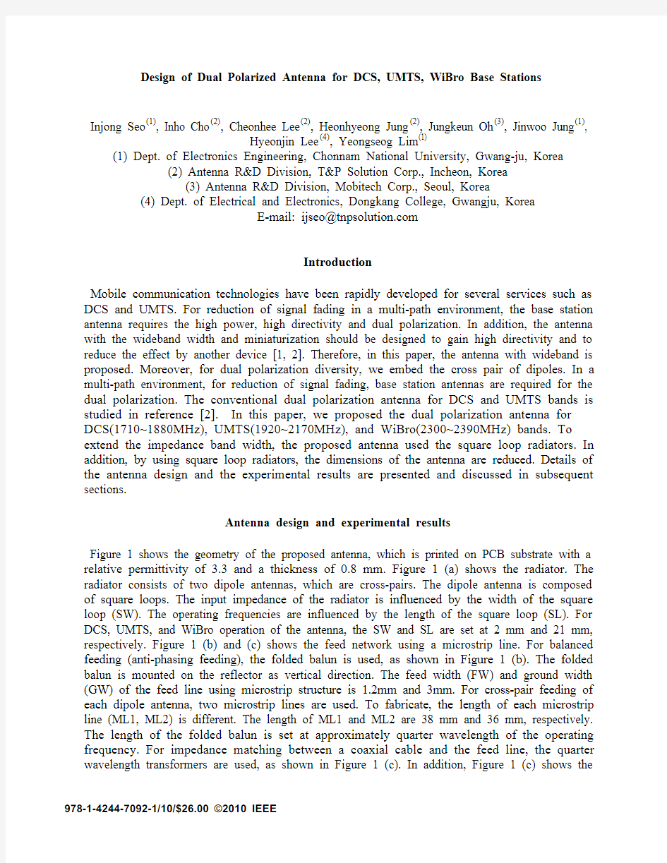
Figure 1 shows the geometry of the proposed antenna, which is printed on PCB substrate with a relative permittivity of 3.3 and a thickness of 0.8 mm. Figure 1 (a) shows the radiator. The radiator consists of two dipole antennas, which are cross-pairs. The dipole antenna is composed of square loops. The input impedance of the radiator is influenced by the width of the square loop (SW). The operating frequencies are influenced by the length of the square loop (SL). For DCS, UMTS, and WiBro operation of the antenna, the SW and SL are set at 2 mm and 21 mm, respectively. Figure 1 (b) and (c) shows the feed network using a microstrip line. For balanced feeding (anti-phasing feeding), the folded balun is used, as shown in Figure 1 (b). The folded balun is mounted on the reflector as vertical direction. The feed width (FW) and ground width (GW) of the feed line using microstrip structure is 1.2mm and 3mm. For cross-pair feeding of each dipole antenna, two microstrip lines are used. To fabricate, the length of each microstrip line (ML1, ML2) is different. The length of ML1 and ML2 are 38 mm and 36 mm, respectively.
The length of the folded balun is set at approximately quarter wavelength of the operating frequency. For impedance matching between a coaxial cable and the feed line, the quarter wavelength transformers are used, as shown in Figure 1 (c). In addition, Figure 1 (c) shows the 978-1-4244-7092-1/10/$26.00 ?2010 IEEE
reflector. The reflector consists of the main reflector and the choke. The distance between the radiator and the main reflector is 40 mm, which is approximately quarter wavelength of the operating frequency. By varying the reflector shape, the beam width in the horizontal plane can easily be controlled. To obtain the beam width in horizontal plane of from 65 degree to 75 degree, the dimensions of the reflector are set as follows: RL=200 mm, RW=100mm, and CH = 10 mm, as shown in Figure 1 (c).
The antenna was analyzed and optimized by CST Microwave Studio 2008 Software. Figure 1 (d) shows the 3-dimensional view of the proposed antenna.
For dual-polarization, the dipole antennas are cross-pairs. Squared loop radiators extend the impedance bandwidth of the dipole antenna. When dipole antennas are situated in cross-pairs, in far-field, the radiation characteristics are orthogonal. Therefore, the inter-isolation is in good condition. To obtain the inter-isolation of good condition, the dipole antennas of the proposed antenna, which have square loop radiators, are situated in cross-pairs. When only dipole antenna 1 is fed, the square loops of dipole antennas are considered parasitic elements. When a dipole antenna has parasitic elements, the impedance bandwidths can be extended. Therefore, in the case of the proposed antenna, the impedance bandwidth is extended. However, in dipole antenna 2, the coupled currents occur. Because the dipole antenna 2 is fed, the coupled currents should be considered. By dipole antenna 1, in each square loop of the dipole antenna 2, the coupled currents of half wavelength occur. Therefore, the coupled current distributions of the dipole antenna 2 are one wavelength. The electrical length of a general dipole antenna is half wavelength. When the electrical length of a dipole antenna is one wavelength, the resonance frequency of the dipole antenna is anti-resonance frequency. At anti-resonance frequency, the dipole antenna has very high resistance. As a result, the coupled current, which occurs by the dipole antenna 1, can not be influence in dipole antenna 2. The coupled current, which is occurred by dipole antenna 2, can not be influence in dipole antenna 1 for the same reason. Figure 3 shows the photograph of the fabricated antenna. The size of an actual fabricated radiator is 45mm × 45mm (L×W), which is 11% smaller than the conventional antenna [2].
Figure 4 shows the measured return loss in port 1 (S11) port 2 (S22), and the measured isolation between two radiators (S21), at operating frequencies from 1.71 GHz to 2.39 GHz. The obtained results show that the S11 and S22 are less than –14dB, and intra isolation is less than –25dB. By the difference of the geometry of each feed line and the location of each dipole antenna, the S11 and S22 are different.
Figure 5 shows the measured radiation patterns (E plane and H plane) at 1.71 MHz, 1.88 MHz, 1.92 MHz, 2.17 MHz, 2.3MHz, and 2.39 MHz, respectively.
Table 1 shows the peak gain and HPBW of proposed antenna at each frequency.
Conclusions
In this paper, we proposed the dual polarization antenna for DCS, UMTS, and WiBro bands. To extend the impedance band width, the proposed antenna used the square loop radiators. In addition, by square loop radiators, the dimensions of an antenna are reduced. As a result of measurement after compensation, we can see that the first port is less than -14dB, the second port is less than -14dB and intra isolation is less than -25dB. Additionally, a gain of the antenna is more than 9dBi. This polarization diversity antenna element can be used to form an array antenna for a wireless communication base station.
(a) Radiator with anti-phase cross section(b) Feeder line & folded balun
(c) Feeder line & reflector (d) The 3D structure
SL=21, SW=2, DG=3, ML1=38, ML2=36, W=25, GW=3, FW=1.2, BW=3, BL=40, RL=200, RW=100, CH=10, Unit : [mm]
Figure 1 The Structure of proposed antenna
Figure 2 Photograph of the fabricated antenna Figure 3 S-Parameter characteristic of proposed antenna
(a) H plane radiation pattern of dipole (b) E plane radiation pattern of dipole Figure 4 Measured radiation pattern at port 1
Table 1 Gain and HPBW of proposed antenna
Frequency
[MHz] H plane
E plane Max.
Gain
[dBi] HPBW [°] Max. Gain
[dBi] HPBW [°]
1710 9.74 65.16 9.68 61.62
1880 9.92 65.45 9.44 69.32
1920 9.52 66.48 9.37 68.79
2170 9.17 73.52 9.16 65.86
2300 9.12 74.27 9.21 63.87
2390 9.10 74.68 9.23 72.85
References
[1] Wu Di, Yin Yingzeng, Guo Minjun and Shen Renqiang, “Wideband Dipole Antenna for 3G
Base Stations”, IEEE International Symposium on Microwave, Antenna, Propagation and EMC Technologies for Wireless Communications Proceedings, pp.454-457, 2005.
[2] Daoyi Su, Jason J. Qian, Hua Yang and Demin Fu, “A Novel Broadband Polarization
Diversity Antenna Using A Cross-Pair of Folded Dipoles”, APMC, 2005.
[3] Gangyi Deng, Bill Vassilakis, “A Broadband Dual Polarized Antenna Element for Wireless
Communications”, IEEE Antennas and Propagation Society International Symposium, pp.4717-4720, 2007.
[4] Warren L. Stutzman, “Antenna Theory And Design” 1998.