POE60U-560(G);中文规格书,Datasheet资料
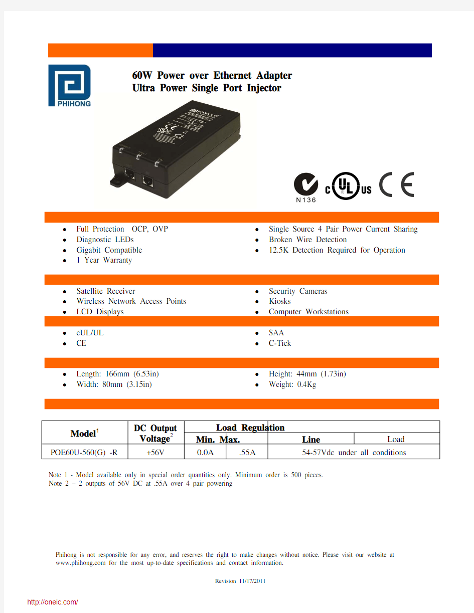

https://www.360docs.net/doc/4c17511957.html, 60W Power over Ethernet Adapter
Ultra Power Single Port Injector
Features
? Full Protection OCP, OVP ? Single Source 4 Pair Power Current Sharing ? Diagnostic LEDs ? Broken Wire Detection
? Gigabit Compatible ? 12.5K Detection Required for Operation
? 1 Year Warranty
Applications
? Satellite Receiver
? Security Cameras ? Wireless Network Access Points ? Kiosks
? LCD Displays
? Computer Workstations
Safety Approvals
? cUL/UL ? SAA ? CE ? C-Tick
Mechanical Characteristics
? Length: 166mm (6.53in) ? Height: 44mm (1.73in) ? Width: 80mm (3.15in) ? Weight: 0.4Kg
Output Specifications
Note 1 - Model available only in special order quantities only. Minimum order is 500 pieces.
Note 2 – 2 outputs of 56V DC at .55A over 4 pair powering
Phihong is not responsible for any error, and reserves the right to make changes without notice. Please visit our website at Model 1
DC Output
Voltage 2
Load Regulation
Min. Max. Line
Load POE60U-560(G) -R
+56V
0.0A .55A 54-57Vdc under all conditions
POE60U-560(G)-R Characteristics https://www.360docs.net/doc/4c17511957.html,
INPUT:
AC Input Voltage Range
90 to 264VAC
AC Input Voltage Rating
100 to 240VAC, 47-63Hz
AC Input Current
2A (RMS) maximum for 90VAC
1.2A (RMS) maximum for 240VAC
Leakage Current
3.5mA maximum @ 254VAC 60Hz
AC Inrush Current
30A (RMS) maximum for 115VAC
40A (RMS) maximum for 230VAC OUTPUT:
Total Output Power
60W
DC Offset
No data degradation with DC imbalance 18mA per min.
Efficiency
75% (typical) at maximum load, and 120VAC 60Hz Hold-up Time
10mS minimum 120VAC and maximum load Transient O/P Voltage Protection
60V maximum
ENVIRONMENTAL:
Temperature
Operation 0 to +40°C
Non-operation -25 to +65°C
Humidity
Operation 5 to 90%
EMC
FCC Part 15 Class B
EN55022 Class B Isolation Test
Primary to Secondary: 4242VDC for 1 minute Primary to Field Ground: 2121VDC for 1 minute Output to Field Ground: 2121VDC
Immunity
ESD: EN61000-4-2. Level 3
RS: EN61000-4-3. Level 2
EFT: EN61000-4-4. Level 2
Surge: EN61000-4-5. Level 3
CS: EN61000-4-6. Level 2
Voltage Dips EN61000-4-11
Harmonic: EN61000-3-2 Class A Insulation Resistance
Primary to secondary: >10M OHM 500VDC Primary to FC: >10M OHM 500VDC FEATURE:
Detection
12.5kohm detection resistor value required to turn on full power 4 pair power.
Over Voltage/Current, Short Circuit Protection
Outputs equipped with short circuit protection and overload protection and the maximum average current is 0.55A, Peak 0.6A per pair. The output can be shorted permanently without damage Indicators
Green LED 1: DC Power “OK”
Red LED: Fault detected
Green LED 2: Power detected “CONNECT” at
60W
Input Connector
IEC320 inlet 3 pin
Warranty
1 Year
Dimension Diagram Unit:mm https://www.360docs.net/doc/4c17511957.html,
Description of LED Functions for Gigabit Power Injector
Power-up Sequence:
Upon power-up, all 3 LEDs will light for 2 seconds, as part of the self-test for the internal
microprocessor software. After the 2 second period, the "ON" LED will illuminate green. The DC
output voltage is available for powering a compliant load.
Detection Sequence:
Once a compliant load is attached to the output RJ45 connector, the green "CONNECT" LED will
illuminate.
Should the load be non-compliant then the LEDs will blink a code specific to the cause for non-
detection.
Detection Failure Codes:
1.Incorrect resistive signature – The green “CONNECT” and red “FAULT” LEDs will blink 3 times.
2.Incorrect capacitive signature – The green “ON” LED will blink 3 times.
3.Incorrect Voffset – The green “CONNECT” and green “ON” LEDs will blink 3 times.
4.Unstable current measurement – The green “ON” LED will blink 3 times
5.Low voltage sensed during detection (overload) – The red “FAULT” LED will blink 3 times
After the LEDs blink 3 times the Power Injector will continue to try to detect a valid load. Until the
correct load is applied, the LEDs will continue to blink. If there is an open circuit connected to the
output RJ45 then the LEDs will not blink but the Power Injector will continue to try to detect a valid
load.
Fault Sequence:
Should there be a fault such as an overload or short circuit then the red "FAULT" LED will illuminate.
The red “FAULT” LED will illuminate for 2 seconds and then go off as the power supply tries to re-
detect a valid load. If there is a problem detecting the load, the LED will indicate the possible fault as per the codes in the section above.
分销商库存信息: PHIHONG
POE60U-560(G)