,英3RCMAC的自适应控制设计无刷直流电机
ORIGINAL ARTICLE
RCMAC-based adaptive control design for brushless DC motors
Chih-Min Lin ?Chun-Fei Hsu ?Chao-Ming Chung
Received:27October 2007/Accepted:24November 2008/Published online:19December 2008óSpringer-Verlag London Limited 2008
Abstract This paper proposes a recurrent cerebellar model articulation controller (RCMAC)-based adaptive control for brushless DC motors.This control system is composed of a RCMAC and a compensation controller.RCMAC is used to mimic an ideal controller,and the compensation controller is designed to compensate for the approximation error between the ideal controller and RCMAC.The Lyapunov stability theory is utilized to derive the parameter tuning algorithm,so that the uni-formly ultimately bound stability of the closed-loop system can be achieved.For comparison,a fuzzy control,an adaptive fuzzy control and the developed RCMAC-based adaptive control are implemented on a ?eld programmable gate array chip for controlling a brushless DC motor.Experimental results reveal that the proposed RCMAC-based adaptive control system can achieve the best tracking performance.Moreover,since the developed RCMAC-based adaptive control scheme uses a hyperbolic tangent function to compensate for the approximation error,there is no chattering phenomenon in the control effort.Thus,the proposed control method is more suitable for real-time practical control applications.
Keywords Recurrent CMAC á
Uniformly ultimately bound stability áBrushless DC motor áFPGA
1Introduction
Recently,brushless DC (BLDC)motors have gradually been used in the motion control,because their advantages include simple to construct,high-torque capability,small inertia,low noise and long-life operation [1].Unfortu-nately,BLDC motor is a non-linear system whose internal parameter values will change slightly with different input commands and environments.Several investigations have been carried out in recent years to apply various control approaches for BLDC motor control [2–4].Liu et al.[2]proposed a PI controller to achieve instantaneous torque control with reduced torque ripple.However,the selection of PI gains is a trade-off between robustness and fast transient response.Rubaai et al.[3]proposed an adaptive fuzzy-neural-network controller to achieve satisfactory tracking performance.However,the computational loading is too complex.Rubaai et al.[4]proposed a robust adaptive fuzzy controller.The experimental results show that robust tracking performance can be achieved;however,the con-trol effort may lead to a large control signal as the speci?ed robustness is increased.
Based on the approximation ability of neural network (NN),the NN-based adaptive controllers have been developed to compensate for the effects of non-linearities and system uncertainties [5–8].To obtain the fast learn-ing property and good generalization capability,the cerebellar model articulation controller (CMAC)has been proposed [9].CMAC is classi?ed as a non-fully con-nected perceptron-like associative memory network with
C.-M.Lin (&)áC.-M.Chung
Department of Electrical Engineering,Yuan Ze University,Chung-Li,Tao-Yuan 320,Taiwan,ROC e-mail:cml@https://www.360docs.net/doc/4218599162.html,.tw C.-M.Chung
e-mail:s948507@https://www.360docs.net/doc/4218599162.html,.tw
C.-F.Hsu
Department of Electrical Engineering,
Chung Hua University,Hsinchu 300,Taiwan,ROC e-mail:fei@https://www.360docs.net/doc/4218599162.html,.tw
Neural Comput &Applic (2009)18:781–790DOI 10.1007/s00521-008-0230-2
overlapping receptive-?elds.CMAC has been already validated that it can approximate a non-linear function over a domain of interest to any desired accuracy.There has been considerable interest in exploring the applica-tions of CMAC to deal with the non-linearity and uncertainty of control systems[10–13].It has been shown that the CMAC-based adaptive control systems can achieve better control performance than NN-based adap-tive control systems by appropriately designing the CMAC controller[14,15].
According to the structure,the NNs can be mainly classi?ed as feedforward neural networks(FNNs)and recurrent neural networks(RNNs)[16].As known,FNN is a static mapping.Without the aid of tapped delays, FNNs are unable to represent a dynamic mapping.As far as RNNs are concerned,their ability to deal with time varying input or output through their own natural tem-poral operation is of particular interest.Thus,RNN is a
dynamic mapping and demonstrates good control perfor-mance in the presence of unmodeled dynamics[17,18]. In this study,a recurrent CMAC(RCMAC),which involves dynamic elements in the form of feedback con-nections that are used as internal memories,is developed to design the controller.RCMAC has advantages over CMAC in its dynamic response and its information stor-ing ability.
To tackle the non-linear problem of BLDC motor,this paper proposes a RCMAC-based adaptive control system with a new training algorithm.The RCMAC-based adaptive control system is composed of an RCMAC and a compensation controller.RCMAC is used to mimic an ideal controller and it presents the main controller.The compensation controller using a hyperbolic tangent func-tion is derived to compensate for the difference between the ideal controller and RCMAC.Since RCMAC has an internal feedback loop,it captures the dynamic response of system with external feedback through delays.More-over,all the parameters of the RCMAC-based adaptive control system are tuned in the Lyapunov sense,thus the uniformly ultimately bounded stability can be guaranteed. The stability analysis shows that the output of the system can exponentially converge to a small neighborhood of the trajectory command.Finally,the proposed RCMAC-based adaptive control system is implemented based on a ?eld programmable gate array(FPGA)chip for possible low-cost and high-performance industrial applications.A comparison between a fuzzy controller,an adaptive fuzzy controller and the proposed RCMAC-based adaptive controller is made.The experimental results demonstrate that the proposed RCMAC-based adaptive control scheme can achieve better control performance than the other control methods.2RCMAC approximator
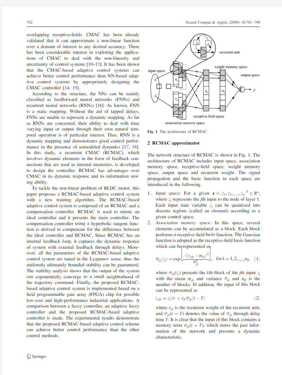
The network structure of RCMAC is shown in Fig.1.The architecture of RCMAC includes input space,association memory space,receptive-?eld space,weight memory space,output space and recurrent weight.The signal propagation and the basic function in each space are introduced in the following.
1.Input space:For a given z??z1;z2;...;z n T2R n;
where z j represents the j th input to the node of layer1.
Each input state variable z j can be quantized into discrete regions(called an element)according to a given control space.
2.Association memory space:In this space,several
elements can be accumulated as a block.Each block performs a receptive-?eld basis function.The Gaussian function is adopted as the receptive-?eld basis function which can be represented as
u jkez jT?exp
àez rjkàm jkT2
r
jk
"#
;for k?1;2;...;n Be1T
where u jk(z j)presents the k th block of the j th input z j with the mean m jk and variance r jk and n B is the number of blocks.In addition,the input of this block can be represented as
z rjk?z jetTtr jk u jketàTTe2Twhere r jk is the recurrent weight of the recurrent unit, and u jk(t-T)denotes the value of u jk through delay time T.It is clear that the input of this block contains a memory term u jk(t-T),which stores the past infor-mation of the network and presents a dynamic
characteristic.
Fig.1The architecture of RCMAC
3.
Receptive-?eld space :In this receptive-?eld space,the multidimensional receptive-?eld function is de?ned as
b q ez T?Y n j ?1u jk ez rjk T?exp X n j ?1àez rjk àm jk T
2r jk "#
;for q ?1;2;...;n R
e3T
where b q is associated with the q th receptive-?eld.
De?ne the vectors m ,r and r collecting all parameters of the membership layer as
m ?m 11;...;m n 1;m 12;...;m n 2;...;m 1n B ;...;m nn B ? T e4Tr ?r 11;...;r n 1;r 12;...;r n 2;...;r 1n B ;...;r nn B ? T e5Tr ?r 11;...;r n 1;r 12;...;r n 2;...;r 1n B ;...;r nn B ? T :
e6T
The multidimensional receptive-?eld function can be expressed in a vector notation as
H ?b 1;...;b q ;...;b n R ??T
:e7T4.
Weight memory space :Each location of R to a particular adjustable value in the weight memory space with n R components can be expressed as
w ?w 1;...;w q ;...;w n R ??e8Twhere w q denotes the connecting weight value of the q th receptive-?eld.
5.
Output space :The output of RCMAC is the algebraic sum of the activated weights in the weight memory,and is expressed as y ?
X n R q ?1
w q b q :e9T
The output of RCMAC can be expressed in a vector
notation as y ?w T H ez ;m ;r ;r T:
e10T
This implies that there exists an RCMAC of (10)such that it can uniformly approximate a non-linear even time-varying function X .By the universal approximation theorem,there exists ideal weight vectors such that [19]X ?y ?
tD ?w ?T
H ez ;m ?
;r ?
;r ?
TtD ?w ?T
H ?
tD
e11T
where D denotes the approximation error,w *and H *are the optimal parameter vectors of w and H ,respectively,and m *,r *and r *are the optimal parameter vectors of m ,r and r ,respectively.In fact,the optimal parameter vectors that are needed to best approximate a given non-linear function X cannot be determined.Thus,an estimation function is de?ned as
^y ?^w
T H ez ;^m ;^r ;^r T?^w T ^H e12T
where ^w
and ^H are the estimated parameter vectors of w and H ,respectively,and ^m ;^r ;and ^r are the estimated
parameter vectors of m ,r and r ,respectively.De?ne the estimation error as
~y
?X à^y ?y ?à^y tD ?~w T ~H t^w T ~H t~w T ^H tD e13T
where ~w
?w ?à^w and ~H ?H ?à^H :In the following,some tuning laws will be derived to on-line tune the parameters of RCMAC to achieve favorable estimation of a non-linear function.To achieve this goal,the Taylor expansion linearization technique is employed to transform the non-linear function into a partially linear form,i.e.[19]~H ?A T ~m tB T ~r tC T ~r th e14Twhere ~m
?m ?à^m ;~r ?r ?à^r ;~r ?r ?à^r ;
h is a
vector of higher-order terms;
A ?o H 1o m o H 2o m áááo H n R o m ! m ?^m
B ?
o H 1o r o H 2o r áááo H n R o r ! r ?^r C ?
o H 1o r o H 2o r áááo H n R o r ! r ?^r
:Substituting (14)into (13),yields
~y
?~w T ~H t^w T eA T ~m tB T ~r tC T ~r th Tt~w T ^H tD ?~w
T ^H t~m T A ^w t~r T B ^w t~r T C ^w te e15T
where ^w T A T ~m ?~m T A ^w ;^w T B T ~r ?~r T B ^w and ^w T C T ~r ?~r T C ^w
are used since they are scales,and the uncertain term e ?^w
T h t~w T ~H tD denotes the approximation error,and is assumed to be bounded by 0B |e |B E *,in which E *is a positive constant.However,this uncertainty bound E *cannot be obtained in practice,so that it will be on-line estimated and will be discussed in the following section.3RCMAC-based adaptive controller design 3.1Modeling of a brushless DC motor
The system equations of BLDC motor driver in a d –q model can be expressed as [4]i qs ?àR s L q i qs àL d L q x r i ds t1L q v qs àk m
L q x r
e16Ti ds ?à
R s L d i ds tL q L d
x r i qs t1
L d v ds
e17T
L q?L istL mqe18TL d?L istL mde19Twhere i ds and i qs represent the d and q axes stator currents,respectively,R s is the stator resistance,L d and L q are the d and q axes stator inductances,respectively, L is is the stator leakage inductance,L md and L mq are the d and q axes magnetizing inductances,respectively,x r is the electrical rotor angular velocity,and k m is the?ux linkage of permanent magnet.The torque equation is expressed as
T e?3
2
N
2
?k m i qsteL dàL qTi qs i ds ?J
N
2
_x rtB
N
2
x rtT L
e20T
where N is the number of poles,J is the inertia of the rotor, B is the damping coef?cient,and T L is the load disturbance. By using the?eld-oriented control,the torque equation of BLDC motor driver can be expressed as
T e?3
2
N
2
k m i qs?k t i qse21T
where k t?3
2N
2
k m is the constant gain.From(20)and(21),
it can obtain
€h?f_htguthe22T
where h?R
x r d t is a position of rotor,f?àB
J
;g?
2 N k t
J
;h?à2
N
1
J
T L;and u=i qs is the control effort.
3.2Control system design
The control objective of the BLDC motor driver is to ?nd a control law so that the rotor position h can track the position command h c closely.De?ne the tracking error as
e?h càh:e23TAssume that the parameters of the controlled system in (22)are well known,there exits an ideal controller
u??gà1eàf_hàht€h ctk1_etk2eTe24Twhere k1and k2are positive constants.Applying the ideal controller(24)into(22)results in the following error dynamics
€etk1_etk2e?0:e25TIf k1and k2are chosen such that all roots of the polynomial hesTD s2tk1stk2lie strictly in the open left
half of the complex plane,then it implies that lim
t!1e?0for
any starting initial conditions.However,since the system dynamics f and g,and the disturbance h may be unknown or perturbed in practical applications,the ideal controller u*in(24)cannot be precisely obtained.
To tackle this problem,the RCMAC-based adaptive control system for BLDC motor driver is proposed and shown in Fig.2,where the control law is designed as
u?u RCMACtu rb:e26TThe RCMAC u RCMAC is used to mimic the ideal con-troller u*and the robust controller u rb is used to compensate for the difference between RCMAC and ideal controller.Substituting(26)into(22)and using(15),the error dynamic equation can be obtained as
_e?A m etbeu?àu RCMACàu rbT
?A m etbe~w T^Ht~m T A^wt~r T B^wt~r T C^wteàu rbT
e27Twhere A m?
01
àk2àk1
!
and b=[0,1]T.To guarantee the stability of the RCMAC-based adaptive control system, the Lyapunov function is de?ned as
V?
1
2
e T Pet
1
2g1
~w T~wt
1
2g2
~m T~mt
1
2g3
~r T~rt
1
2g4
~r T~r
t
1
2g5
~E2e28T
where the positive constants g1,g2,g3,g4and g5are the learning-rates,the estimation error of error bound is de?ned as~E?E?à^E where^E is the estimation of E*, and P is a symmetric positive de?nite matrix that satis?es the Lyapunov equation
A T
m
PtP T A m?àQe29Tand Q is a positive de?nite matrix.Taking the derivative of Lyapunov function in(28)and using(27),
yields
_V?1
2_e T Pet
1
2
e T_Pet
1
g1
~w T_~wt
1
g2
~m T_~wt
1
g3
~r T_~r
t1
g4
~r T_~wt
1
g5
~E_~E
?1
2
e T A T
m
PtPA m
àá
ete T Pb
à
~w T^Ht~m T A^wt~r T B^w
t~r T C^wteàu rb á
à
1
g1
~w T_^wà
1
g2
~m T_^mà
1
g3
~r T_^r
à1
g4
~r T_^rà
1
g5
~E_^E
?à1
2
e T Qet~w T e T Pb^Hà
_^w
g1
!
t~m T e T PbA^wà
_^m
g2
!
t~r T e T PbB^wà
_^r
g3
!
t~r T e T PbC^wà
_^r
g4
!
te T Pbeeàu rbTà
1
g5
~E_^E:
e30T
If the adaptation laws of RCMAC are chosen as
_^w?g
1
e T Pb^Hàl1e^wà^w0T
h i
e31T
_^m?g
2
e T PbA^wàl2e^mà^m0T
??
e32T
_^r?g
3
e T PbB^wàl3e^rà^r0T
??
e33T
_^r?g
4
e T PbC^wàl4e^rà^r0T
??
e34T
where l1,l2,l3and l4are positive small constants, ^w0;^m0;^r0and^r0are initial estimation vectors of w*,m*, r*and r*,respectively.The robust controller with bound estimation law is chosen as
u rb?^E tan h
e T Pb
d
e35T
_^E?g
5e T Pb tan h
e T Pb
àl5e^Eà^E0T
!
e36T
where tan h(á)is a hyperbolic tangent function,d and l5 are small positive constants,and^E0is initial estimation value of E*.The adaptation laws comprise a variant of the l-modi?cation,which allow the designer to incorporate any a priori parameter knowledge.In the absence of any a priori information,^w0;^r0and^E0can be simply set to zero,^m0can be assigned with equal distribution in the considered ranges and^r0can be set as a value to let the intersection of two neighbor receptive-?eld basis function will be equal to0.5.Then(30)can be rewritten as
_V?à1
2
e T Qet~w T l1e^wà^w0Tt~v T l2e^mà^m0T
t~r T l3e^rà^r0Tt~r T l4e^rà^r0T
te T Pb eà^E tan h
e T Pb
d
!
à~E e T Pb tan h
e T Pb
d
àl5e^Eà^E0T
!
à
1
2
e T Qet~w T l1e^wà^w0Tt~v T l2e^mà^m0T
t~r T l3e^rà^r0Tt~r T l4e^rà^r0T
tE?e T Pb
àe T Pb tan h
e T Pb
d
!
t~E l5e^Eà^E0T:
e37TIt can be found that the following inequality holds for any d[0[20]
0e T Pb
àe T Pb tan h
e T Pb
d
jde38T
where j is a constant satisfying j=exp(-(j?1)). Using the inequality(38),(37)can be rewritten as
_Và1
2
e T Qet~w T l1e^wà^w0Tt~v T l2e^mà^m0T
t~c T l3e^rà^r0Tt~r T l4e^rà^r0T
t~E l5e^Eà^E0TtE?k d
à
1
2
e T QetE?jdà
1
2
l1~w
k k2tl2~m
k k2tl3~r k k2
tl4~r k k2tl5~E
2
t
1
2
l1w?à^w0
k k
eT2
h
tl2m?à^m0
k k
eT2tl3r?à^r0
k k
eT2tl4r?à^r0
k k
eT2tl5E?à^E0
àá2i
e39TChoosing Q=I and considering the Lyapunov function (28),(39)can be obtained as
_Vàa Vtbe40Twhere a and b are positive constants given by
a?min
1
k maxePT
;l1g1;l2g2;l3g3;l4g4;l5g5
e41Tb?
1
2
l1w?à^w0
k k
eT2tl2m?à^m0
k k
eT2
h
tl3r?à^r0
k k
eT2tl4r?à^r0
k k
eT2tl5E?à^E0
àá2i tE?jd:e42TThus,the uniformly ultimately bound stability of the closed-loop system can be achieved[20].
4Experimental results
Field programmable gate array is a fast prototyping IC
component.This kind of IC incorporates the architecture of a gate array and programmability of a programmable logic device.The advantage of controller implemented by FPGA includes short development cycles,low cost,small size,fast system execution speed,and high ?exibility.In the FPGA design,the Altera Quartus II software and hardware description language Verilog are used in this study.The hardware is implemented by Altera Stratix II series FPGA chip with 50MHz clock frequency.The external peripheral interfaces are used to transmit and receive the motor driver signals through a 12-bits encoder counter circuit and a 12-bits D/A converter circuit.The encoder counter circuit is comprised of an encoder signal delay IC,motor rota-tional direction gauge IC,and three 4-bits up–down counter ICs for calculating the rotor position of BLDC motor.The 12-bits D/A converter IC with dual channel voltage output is used to control the BLDC motor.Additionally,every IC that connects with the FPGA chip uses asynchronous bus transceiver IC to protect the current re?ow to FPGA chip.The experimental setup is shown in Fig.3.To illustrate the effectiveness of the proposed design method,a comparison between a fuzzy controller,an adaptive fuzzy controller,and the proposed RCMAC-based adaptive controller is made.
4.1Comparison of different control methods
To compare the tracking ef?ciency,?rst a fuzzy controller is applied to control the BLDC motor.The fuzzy control rules are given in the following form:
Rule i :IF e is F i e and _e is F i
_e ;
THEN u is q i
e47T
where q i ,i =1,2,…,n are the singleton control actions,
and F e i and F i
_e are the labels of the fuzzy sets with Gaussian membership function.The fuzzy rules are summarized in Table 1,where the fuzzy labels used in this paper are negative big (NB),negative medium (NM),negative small (NS),zero (ZO),positive small (PS),positive medium (PM)and positive big (PB).The fuzzy rules in Table 1are
constructed in such a way that e and _e
will approach to zero with fast rise time and without large overshoot.The de-fuzzi?cation of the controller output is accomplished by the method of sum of weightings.The experimental results of the fuzzy controller are shown in Fig.4.The tracking response is depicted in Fig.4a,the associated control effort is depicted in Fig.4b,and the tracking error is depicted in Fig.4c,respectively.From the experimental results,the fuzzy controller can achieve tracking performance for a start;however,the degenerate tracking response occurs as the frequency of the input command is increased at the 5.5th second.Next,an adaptive fuzzy controller proposed in [3]is applied to control the BLDC motor again.The experimental results of the adaptive fuzzy controller are shown in Fig.5.The tracking response is depicted in Fig.5a,the associated control effort is depicted in Fig.5b,and the tracking error is depicted in Fig.5c.Though the tracking performance can be achieved after learning,there exists the undesirable control chattering in Fig.5b.4.2RCMAC-based adaptive control
It should be emphasized that the development of RCMAC-based adaptive control system does not need to know the system dynamics of the controlled system.For practical implementation,the parameters of the RCMAC-based adaptive control system can be on-line tuned by the pro-posed adaptive laws without the need of system parameters.Finally,the proposed RCMAC-based adaptive control system is applied to control the BLDC motor to illustrate its effectiveness.For the control system,choosing Q =I ,k 1=2,k 2=1and solving A m T P ?PA m =-Q ,it can be
obtained
Fig.3The experimental setup
Table 1Fuzzy control rules base _
e e NB
NS ZO PS PB NB -2.0-2.0-2.0-1.00.0NS -2.0-2.0-1.00.0 1.0ZO -2.0-1.00.0 1.0 2.0PS -1.00.0 1.0 2.0 2.0PB
0.0
1.0
2.0
2.0
2.0
P?1:76250:7812
0:78120:8088
!
:e48T
The parameters of adaptive laws are chosen as g1?0:02;g2?g3?g4?0:0002;g5?0:00002;d?0:1and l1?l2?l3?l4?l5?0:01:The initial estimation vectors of^w0;^r0;and^E0are all set to0,^m0is set as equal distribution in the range betweenà1:92;1:92
? and ^r0is set as0.58.All the gains are chosen to achieve satisfactory transient control performance in considering the requirement of stability and possible operating conditions.The experimental results of the RCMAC-based adaptive control system are depicted in Fig.6.The tracking response is depicted in Fig.6a,the associated control effort is depicted in Fig.6b,and tracking error is depicted in Fig.6c.It can be seen that there is no chattering phenomena in the control effort and perfect tracking response can be obtained after initial transient response. From the comparison of experimental results,it is shown that the RCMAC-based adaptive control system
can
achieve better tracking performance than other control methods.Additionally,the performance comparison between a fuzzy controller,an adaptive fuzzy controller, and the proposed controller is made as shown in Table2, which shows that the proposed RCMAC-based adaptive control pay the price of a little larger computational load for achieving better control performance.However, this computational load is acceptable for practical application.5Conclusions
In this paper,an RCMAC-based adaptive control system with a novel training algorithm for a brushless DC motor has been successfully developed and implemented based on the FPGA approach.The implementation of the control system using the FPGA can achieve the charac-teristics of small size,fast execution speed and less memory.All the parameters of the proposed
RCMAC-system
based adaptive control system can be tuned based on the Lyapunov stability theorem;thus,the uniformly ultimately bound stability of the control system is guaranteed.The effectiveness of the proposed RCMAC-based adaptive control has been veri?ed by experimental
results.
control system
Table 2Controller
characteristic comparison
Controller Controller parameters Stability proof Robustness Chattering phenomena Fuzzy control Trial and error No Middle No Adaptive fuzzy control On-line learning Yes Good Yes RCMAC-based adaptive control
On-line learning
Yes
Excellent
No
Acknowledgments The authors appreciate partial support from the National Science Council of Republic of China under grant NSC 95-2622-E-155-004-CC3.
References
1.Dote Y,Kinoshita S(1990)Brushless servomotors:fundamentals
and applications.Clarendon Press,Oxford
2.Liu Y,Zhu ZQ,Howe D(2005)Direct torque control of brushless
DC drives with reduced torque ripple.IEEE Trans Ind Appl 41(2):599–608.doi:10.1109/TIA.2005.844853
3.Rubaai A,Ricketts D,Kankam MD(2002)Development and
implementation of an adaptive fuzzy-neural-network controller for brushless drives.IEEE Trans Ind Appl38(2):441–447.doi:
10.1109/28.993165
4.Rubaai A,Ofoli AR,Cobbinah D(2007)DSP-based real-time
implementation of a hybrid H?adaptive fuzzy tracking controller for servo-motor drives.IEEE Trans Ind Appl43(2):476–484.doi:
10.1109/TIA.2006.889904
5.Hsu CF,Lin CM,Chen TY(2005)Neural-network-identi?cation-
based adaptive control of wing rock motion.IEE Proc Contr Theor Appl152(1):65–71.doi:10.1049/ip-cta:20050904
6.Duarte-Mermoud MA,Suarez AM,Bassi DF(2005)Multivari-
able predictive control of a pressurized tank using neural networks.Neural Comput Appl15(1):18–25.doi:10.1007/ s00521-005-0003-0
7.Leu YG,Wang WY,Lee TT(2005)Observer-based direct
adaptive fuzzy-neural control for nonaf?ne nonlinear systems.
IEEE Trans Neural Netw16(4):853–861.doi:10.1109/TNN.
2005.849824
8.Lin CM,Hsu CF(2003)Neural network hybrid control for
antilock braking systems.IEEE Trans Neural Netw14(2):351–359.doi:10.1109/TNN.2002.806950
9.Jan JC,Hung SL(2001)High-order MS CMAC neural network.
IEEE Trans Neural Netw12(3):598–603.doi:10.1109/72.92556210.Shiraishi H,Ipri SL,Cho DD(1995)CMAC neural network
controller for fuel-injection systems.IEEE Trans Contr Syst Technol3(2):32–38.doi:10.1109/87.370707
11.Su SF,Tao T,Hung TH(2003)Credit assigned CMAC and its
application to online learning robust controllers.IEEE Trans Syst Man Cybern B33(2):202–213.doi:10.1109/TSMCB.2003.
810447
12.Lin CM,Peng YF(2004)Adaptive CMAC-based supervisory
control for uncertain nonlinear systems.IEEE Trans Syst Man Cybern B34(2):1248–1260.doi:10.1109/TSMCB.2003.822281 13.Lin CM,Peng YF(2005)Missile guidance law design using
adaptive cerebellar model articulation controller.IEEE Trans Neural Netw16(3):636–644.doi:10.1109/TNN.2004.839358 14.Su SF,Lee ZJ,Wang YP(2006)Robust and fast learning for
fuzzy cerebellar model articulation controllers.IEEE Trans Syst Man Cybern B36(1):203–208.doi:10.1109/TSMCB.2005.
855570
15.Lin CM,Chen LY,Chen CH(2007)RCMAC hybrid control for
MIMO uncertain nonlinear systems using sliding-mode technol-ogy.IEEE Trans Neural Netw18(30):708–720.doi:10.1109/ TNN.2007.891198
16.Lin CT,Lee CSG(1996)Neural fuzzy systems:a neuro-fuzzy
synergism to intelligent systems.Prentice-Hall,Englewood Cliffs 17.Lin CM,Hsu CF(2004)Supervisory recurrent fuzzy neural
network control of wing rock for slender delta wings.IEEE Trans Fuzzy Syst12(5):733–742.doi:10.1109/TFUZZ.2004.834803 18.Leung CS,Tsoi AC(2005)Combined learning and pruning for
recurrent radial basis function networks based on recursive least square algorithms.Neural Comput Appl15(1):62–78.doi:10.
1007/s00521-005-0009-7
19.Wang LX(1994)Adaptive fuzzy systems and control:design and
stability analysis.Prentice-Hall,Englewood Cliffs
20.Park JH,Seo SJ,Park GT(2003)Robust adaptive fuzzy con-
troller for nonlinear system using estimation of bounds for approximation errors.Fuzzy Sets Syst(133):19–36.doi:10.1016/ S0165-0114(02)00137-9
一种无刷直流电动机控制系统设计
一种无刷直流电动机控制系统设计
————————————————————————————————作者:————————————————————————————————日期:
一种无刷直流电动机控制系统设计 摘要:介绍了MOTORALA公司专门用于无刷直流电机控制的芯片MC33035和 MC33039的特点及其工作原理,系统设计分为控制电路与功率驱动电路两大部分,控制电路以MC33035/33039为核心,接收反馈的位置信号,与速度给定量合成,判断通电绕组并给出开关信号。在驱动电路设计中,采用三相Y联结全控电路,使用六支高速MOSFET 开关管组成。通过实验,电机运行稳定。 关键词:无刷直流电机;MC33035/33039;控制电路;驱动电路 Design of control system for Brushless DC Motors SUN GuanQun;SHI Ming;TONG LinYi;XU YiPing Abstract:It introduces the MOTORALA company used for the characteristics o f the chip MC33035 and MC33039 which control the brushless direct curren t motor exclusively and its work principle. The system design divides into tw o major parts: the control circuit and the power driver circuit, the control circ uit take MC33035/33039 as the core, receive feedback position signal, with th e speed to the quota synthesis, the judgment circular telegram winding and p roduces the switching signal. In the actuation circuit design, uses the three-p hase Y joint all to control the electric circuit, uses six high speed MOSFET swit ching valve to compose. Through the experiment, the electric motor moveme nt stable is reliable. Keywords:Brushless DC motor;MC33035/33039;control circuit;drive circuit 1.引言 永磁直流无刷电机是近年来迅速成熟起来的一种新型机电一体化电机。该电机由定子、 转子和转子位置检测元件霍尔传感器等组成,由于没有励磁装置,效率高、结构简单、工作特 性优良,而且具有体积更小、可靠性更高、控制更容易、应用范围更广泛、制造维护更方便 等优点,使无刷电机的研究具有重大意义。 本系统设计是利用调压调速,根据调整供电PWM电源的占空比进而调整电压的方式实 现。本设计采用无刷直流电机专用控制芯片MC33035,它能够对霍尔传感器检测出的位置 信号进行译码,它本身更具备过流、过热、欠压、正反转选择等辅助功能, 组成的系统所需 外围电路简单,设计者不必因为采用分立元件组成庞大的模拟电路,使得系统的设计、调试 相当复杂,而且要占用很大面积的电路板。 MC33035和MC33039这两种集成芯片也可以方便地完成无刷直流电动机的正反转、 运转起动以及动态制动、过流保护、三相驱动信号的产生、电动机转速的简易闭环控制等。
直流无刷电机硬件设计文档
硬件电路设计说明书V1 文档版本 1.0 编写人:彭威 编写时间:2015-06-10 部门:研发部 审核人: 审核时间:
1.引言 1.1编写目的 本文档是无刷直流电机风机盘管电源电路及控制驱动电路的硬件设计说明文档,它详细描述了整个硬件模块的设计原理,其主要目的是为无刷直流电机控制驱动电路的原理图设计提供依据,并作为 PCB 设计、软件驱动设计和上层应用软件设计的参考和设计指导。 1.2产品背景 1.3参考资料 Datasheet:Kinetis KE02 Datasheet:MKE02Z16VLC2 Datasheet:MKE02Z64M20SF0RM Datasheet:FSB50760SFT Datasheet:TNY266 Datasheet:FAN7527 2.硬件电路概述 2.1电源部分 电源部分主要功能是提供400V直流电供给电机,另外提供15V直流电给电机驱动芯片供电。采用反激式开关电源设计。 2.1.1总体方案
设计一款 100W驱动开关电源。给定电源具体参数如下: (1)输入电压:AC 85V~265V (2)输入频率:50Hz (3)工作温度:-20℃~+70℃ (4)输出电压/电流:400V/0.25A (5)转换效率:≧85% (6)功率因数:≧90% (7)输出电压精度:±5% 系统整体框架如下 如图所示为电源的整体架构框图,主要目的是在输入的85~265V、50Hz交流电下,输出稳定的恒压电机驱动直流电。由图可知,电源电路主要包括了前级保护电路模块、差模共模滤波模块、整流模块、功率因数校正模块、DC/DC模块。其中EMI滤波电路能够抑制自身和电源线产生的电磁污染,功率因数校正电路采用Boost有源功率因数
通用无刷直流电机控制器PES331
PES331 3-Phase Brushless DC Motor Controller 10F-2, No. 1, Sec. 2, Dong-Da Road, Hsin-Chu 300, Taiwan, R.O.C. TEL: 886-3-532-7598 + https://www.360docs.net/doc/4218599162.html, Key Features: Support 3-Phase Brushless DC motor with hall IC interface Applications for electric screwdriver, electric drill and electric tooling Programmable motor phase sequence Automatically stop after lockup Re-lockup protection Over current protection 5V operating voltage Pin Diagram and Pin Description PWM_BH DIR_IN PWM_AL PWM_CL AVDD VDD HALL_A HALL_C NC2 PWM_CH PWM_BL PWM_AL START_IN GND VBus AGND CUR_SEN T_CMD NC1 HALL_B PES331(SSOP20-150mil) Pin No. Pin Name I/O Description 1 PWM_CH Output C output signal to control the high side of motor driver 2 PWM_AL Output A output signal to control the low side of motor driver 3 PWM_BL Output B output signal to control the low side of motor driver 4 START_IN Input Start to operate 5 GND - Ground 6 AGND - Analog Ground 7 T_CMD Input Clutch signal Input to set the required torque 8 CUR_SEN Input Analog input to sense motor current
无刷直流电机的驱动及控制
无刷直流电机驱动 James P. Johnson, Caterpiller公司 本章的题目是无刷直流电动机及其驱动。无刷直流电动机(BLDC)的运行仿效了有刷并励直流电动机或是永磁直流电动机的运行。通过将原直流电动机的定子、转子内外对调—变成采用包含电枢绕组的交流定子和产生磁场的转子使得该仿效得以可能。正如本章中要进一步讨论的,输入到BLDC定子绕组中的交流电流必须与转子位置同步更变,以便保持磁场定向,或优化定子电流与转子磁通的相互作用,类似于有刷直流电动机中换向器、电刷对绕组的作用。该原理的实际运用只能在开关电子学新发展的今天方可出现。BLDC电机控制是今天世界上发展最快的运动控制技术。可以预见,随着BLDC的优点愈益被大家所熟知且燃油成本持续增加,BLDC必然会进一步广泛运用。 2011-01-30 23.1 BLDC基本原理 在众文献中无刷直流电动机有许多定义。NEMA标准《运动/定位控制电动机和控制》中对“无刷直流电动机”的定义是:“无刷直流电动机是具有永久磁铁转子并具有转轴位置监测来实施电子换向的旋转自同步电机。不论其驱动电子装置是否与电动机集成在一起还是彼此分离,只要满足这一定义均为所指。”
图23.1 无刷直流电机构形 2011-01-31 若干类型的电机和驱动被归类于无刷直流电机,它们包括: 1 永磁同步电机(PMSMs); 2 梯形反电势(back - EMF)表面安装磁铁无刷直流电机; 3 正弦形表面安装磁铁无刷直流电机; 4 内嵌式磁铁无刷直流电机; 5 电机与驱动装置组合式无刷直流电机; 6 轴向磁通无刷直流电机。 图23.1给出了几种较常见的无刷直流电机的构形图。永磁同步电机反电势是正弦形的,其绕组如同其他交流电机一样通常不是满距,或是接近满距的集中式绕组。许多无刷直流电
51单片机直流无刷电机控制
基于MCS-51单片机控制直流无刷电动机 学号:3100501044 班级:电气1002 :王辉军
摘要 直流无刷电机是同步电机的一种,由电动机本体、位置传感器和电子开关线路三部分组成。其定子绕组一般制成多相(三相、四相、五相不等),转子由永久磁钢按一定极对数(2p=2,4,…)组成。电机转子的转速受电机定子旋转磁场的速度及转子极数(P)影响: N=120.f / P。在转子极数固定情况下,改变定子旋转磁场的频率就可以改变转子的转速。直流无刷电机即是将同步电机加上电子式控制(驱动器),控制定子旋转磁场的频率并将电机转子的转速回授至控制中心反复校正,以期达到接近直流电机特性的方式。也就是说直流无刷电机能够在额定负载围当负载变化时仍可以控制电机转子维持一定的转速。 MCS-51单片机是美国英特尔公司生产的一系列单片机的总称,是一种集成电路芯片,采用超大规模技术把具有数据处理能力的微处理器(CPU)、随机存储器(RAM)、只读存储器(ROM)、输入输出接口电路、定时计算器、串行通信口、脉宽调制电路、A/D转换器等电路集成到一块半导体硅片上,这些电路能在软件的控制下准确、迅速、高效地完成程序设计者事先规定的任务。 本论文将介绍基于MCS-51单片机控制直流无刷电动机的设计,它可以实现控制直流无刷电动机的启动、停止、急停、正反转、加减速等功能。 关键词:单片机,直流无刷电动机,控制系统
直流无刷电动机是在直流电动机的基础之上发展而来的,它是步进电动机的一种,继承了直流电动机的启动转矩大、调速性能好等特点克服了需要换向器的缺点在交通工具、家用电器及中小功率工业市场占有重要的地位。直流无刷电动机不仅在电动自行车、电动摩托车、电动汽车上有着广泛的应用,而且在新一代的空调机、洗衣机、电冰箱、吸尘器,空气净化器等家用电器中也有逐步采用的趋势,尤其是随着微电子技术的发展,直流无刷电动机逐渐占有原来异步电动机变频调速的领域,这就使得直流无刷电动机的应用围越来越广。 本设计就是基于MCS-51系列单片机控制直流无刷电动机,利用所学的知识实现单片机控制直流无刷电动机的启动、停止、急停、正反转,加减速等控制,并对直流无刷电动机运行状态进行监视和报警。详细介绍单片机的种类、结构、功能、适用领域和发展历史、未来前景及其直流无刷电动机的工作原理、控制结构等容,既着重单片机的基本知识、功能原理的深入阐述,又理论联系实际详细剖析单片机控制直流无刷电动机的过程。 1.直流无刷电动机的基本组成 直流无刷电动机是在直流电动机的基础上发展而来的,直流无刷电动机继承了直流电动机启动转矩大、调速性能好的优点,克服了直流电动机需要换向器的缺点,在交通工具、家用电器等生活的方方方面面占有重要的地位。 由于直流无刷电动机既具有交流电动机的结构简单、运行可靠、维护方便等一系列优点,又具备直流电动机的运行效率高、无励磁损耗以及调速性能好等诸多优点,故在当今国民经济各领域应用日益普及。 直流无刷电动机主要由电动机本体、位置传感器和电子开关线路三部分组成。其定子绕组一般制成多相(三相、四相、五相不等),转子由永久磁钢按一定极对数(2p=2,4,…)组成。图3-1所示为三相两极直流无刷电机结构。 三相定子绕组分别与电子开关线路中相应的功率开关器件联结,A、B、
基于无刷直流电机控制系统设计与实现
基于无刷直流电机控制系统设计与实现 发表时间:2017-10-20T11:19:09.350Z 来源:《防护工程》2017年第15期作者:樊圣至[导读] 为了摆脱此系统对进口技术的依赖性,应深入研究其控制系统,提升设计水平,从而实现煤矿开采的自动化。交通运输部东海第一救助飞行队摘要:无刷直流电机具备体积小、效率高以及控制精度高等优势,且在多个领域得到了广泛使用。但在部分控制系统中,外加干扰以及参数摄动等因素干扰了系统的动静态性,基于此,本文在分析无刷直流电机结构与运行原理的基础上,指出了其软硬件方面的优化控制措施,以期为此后无刷直流电机控制系统的设计工作提供更多的参考依据。 关键词:无刷直流电机;控制系统;设计与实现 1 无刷直流电机结构 电机本体、位置测算结构、电子换相逻辑等均属于无刷直流电机的组成结构,且其与永磁同步电机较为相似。相较直流电机,无刷直流电机旋转的转子为磁极,而直流电机为绕组。且定子主要由电枢绕组、定子铁芯以及其他固定部件组成,电枢绕组一般采用三相Y型绕法,而转子磁极则采用稀土永磁钢片组成,安装在转子表面。 2 无刷直流电机软硬件设计2.1系统硬件部分 2.1.1系统硬件结构 系统硬件主要包括整流电路、开关电源电路、控制芯片、信号隔离电路、调试电路、逆变功率电路以及电流电压检测与保护电路等,其具体结构如下图1所示。 图1 无刷直流电机控制系统硬件结构组成图其中键盘控制系统信息,比如完成启动、停机、速度给定以及系统参数的在线修改等工作。系统交流电源通过整流桥获得直流电源,并供给全桥逆变以及开关电源电路。而开关电源电路则为系统提供24V以及5V的直流电源,电压检测电路通过模数转换获得电压时值,通过母线电压的监控实行过压保护动作,而主控芯片则通过判断输入信息进行控制命令。 2.1.2电源部分分路 整个系统能量的主要来源便是电源,且其呈现出交流、直流以及交流的变化过程,整个电路被分为强电与弱电两个组成部分,且单相220伏的交流电在整合后会形成310伏的直流电,为逆变电路以及开关电路提供能量。首先是整流电路,包括单相全桥不可控整流电路以及电容充电电流限制电路两个组成部分,当电机功率为1.5kW时,控制器的输出能力设定为2.2kW,且上电瞬间直流电源对电容充电,断开继电器,且电流在经过电阻的过程中得到缓冲。其次是电源电路,主要由变压器、IC1以及MC7085等部分组成,其中IC1为电源的专门控制面板。且开关电源处于电压工作模式,IC1通过电压反馈调整PWM的输出功率,从而维持电源电压的稳定运行。最后是芯片电源电路,主要采用主控芯片为3.3伏的工作电平。 2.1.3主控芯片以及周边电路研究中采用适合电机控制领域的32位Cortex -M3核的单片机,可以达到较高的运算效率,且其时钟频率为72赫兹,具备丰富的外设资源。在设计管脚分配以及附属电路时应在参考专业手册的基础上进行,第一,对于引脚60的外接电路,芯片应处于下载设置状态,且系统完成后还应焊接0欧姆的电阻,以保持引脚的低电平状态。第二,对于晶振电路应采用8M外部晶体的振荡器,且电源与大地之间连接电容,以排除电源的耦合干扰。第三,PWM信号输出控制电路,应采用安全性较强的芯片,且在芯片输出后以及光电隔离之前设置74ACT244以有效控制信号的总输出。第四,键盘系统属于独立通信模块,设计时应按照协议要求编写通讯软件即可使用。 2.1.4功率器元件以及驱动电路GTO、MOSFET、GTR、IGBT以及IPM等均属于常用的功率开关元件,且设计期间,应根据元件管件的耐压程度、最大开关频率等因素进行选择。本次研究中,电机控制要求较高的开关频率;较小的导通阻抗以及较小的驱动功率,因此可以选择MOSFET、IPM以及IGBT。比较发现,IGBT具备大电流以及低导通阻抗的特点,可以保持开关频率;而IPM则在内部集成了过高电压、过大电流以及高温的检测系统,且可以在引脚处输出故障信号,降低了系统的损害率。但考虑到此次研究的试验性质,因此应选择IGBT的分立元件组建全桥逆变电路,并确定1200伏的耐压与25安的额定电流,上升时间为50毫秒。 2.1.5模拟量采集与故障电路
无刷直流电机控制器的综述【文献综述】
文献综述 电气工程及自动化 无刷直流电机控制器的综述 摘要:实现由专用集成芯片及外围电路构成的一种体积小、结构紧凑、调试方便的无刷 直流电机控制器,实现电机的正反转,并分析了各部分的电路结构。 关键词: MC33035; MC33039;无刷直流电机;控制器; 1引言 无刷直流电机是随着大功率开关器件、专用集成电路、稀有永磁材料、微机、新型控制理论及电机理论的发展而迅速发展起来的一种新型电动机,它比交流电动机的结构简单、运行可靠、维护方便等优点,又具备直流电动机运行效率高、无励磁损耗、调速性能好等特点,因此在当今国民经济的各个领域(如医疗器械、仪器仪表、化工、轻纺以及家用电器等方面) 的应用日益普及。 2无刷电机的控制结构及原理 所谓无刷直流电动机是利用半导体开关电路和位置传感器代替电刷和换向器的直流电动机,也就是,它是把电刷与换向器的机械整流变换为霍尔元件与半导体功率开关元件的电子整流。无刷直流电机由转子和定子两部分组成,转子用永磁材料制成,构成永磁磁极,定子由绕组和铁芯组成,定子铁芯由导磁硅铁片迭压而成,其周上均匀分布的槽中嵌放有很多相电枢绕组。直流无刷驱动器包括电源部及控制部:电源部提供三相电源给电机,控制部分需要转换输入电源频率。 图一 电源部可以直接以直流电输入(一般为24V)或以交流电输入(110V/220 V),如果输入是交流电就得先经转换器转成直流。不论是直流电输入或交流电输入要转入电机线圈前须先用换流器将直流
电压转换成3 相电压来驱动电机,换流器一般由6个功率晶体管分为上臂(A+、B+、C+)臂(A-、B-、C-)连接电机作为控制流经电机线圈的开关。控制部则提供PWM(脉冲宽度调制)决定功率晶体管开关频度及换流器换相的时机。直流无刷电机一般希望使用在当负载变动时速度可以稳定于设定值而不会变动太大的速度控制,所以电机内部装有能感应磁场的霍尔传感器作为之闭回路控制,同时也作为相序控制的依据。 要让电机转动起来,首先控制部就必须根据hall-sensor 感应到的电机转子目前所在位置,然后依照定子绕线决定开启(或关闭)换流器(inverter)中功率晶体管的顺序,如下(图二)inverter 中之AH、BH、CH(这些称为上臂功率晶体管)及AL、BL、CL(这些称为下臂功率晶体管),使电流依序流经电机线圈产生顺向(或逆向)旋转磁场,并与转子的磁铁相互作用,如此就能使电机顺时/ 逆时转动。当电机转子转动到hall-sensor 感应出另一组信号的位置时,控制部又再开启下一组功率晶体管,如此循环电机就可以依同一方向继续转动直到控制部决定要电机转子停止则关闭功率晶体管(或只开下臂功率晶体管);要电机转子反向则功率晶体管开启顺序相反。 图二 基本上功率晶体管的开法可举例如下: AH、BL 一组→AH、CL 一组→BH、CL 一组→BH、AL 一组→CH、AL 一组→CH、BL 一组,但绝不能开成AH、AL 或BH、BL 或CH、CL。此外因为电子零件总有开关的响应时间,所以功率晶体管在关与开的交错时间要将零件的响应时间考虑进去,否则当上臂(或下臂)尚未完全关闭,下臂(或上臂)就已开启,结果就造成上、下臂短路而使功率晶体管烧毁。当电机转动起来,控制部会再根据驱动器设定的速度及加/减速率所组成的命令(Command)与hall-sensor 信号变化的速度加以比对(或由软件运算)再来决定由下一组(AH、BL 或AH、CL 或BH、CL 或……)开关导通,以及导通时间长短。速度不够则开长,速度过头则减短,此部份工作就由PWM 来完成。PWM 是决定电机转速快或慢的方式,如何产生这样的PWM 才是要达到较精准速度控制的核心。高转速的速度控制必须考虑到系统的CLOCK 分辨率是否足以掌握处理软件指令的时间,另外对于hall-sensor信号变化的资料存取方式也影响到处理器效能与判定正确性、实时性。至于低转速的
直流无刷电机的控制系统设计方案
直流无刷电机的控制系统设计方案1 引言 1.1 题目综述 直流无刷电机是在有刷直流电机的基础上发展起来的,它不仅保留了有刷直流电机良好的调试性能,而且还克服了有刷直流电机机械换相带来的火花、噪声、无线电干扰、寿命短及制造成本高和维修困难等等的缺点。与其它种类的电机相比它具有鲜明的特征:低噪声、体积小、散热性能好、调试性能好、控制灵活、高效率、长寿命等一系列优点。基于这么多的优点无刷直流电机有了广泛的应用。比如电动汽车的核心驱动部件、电动车门、汽车空调、雨刮刷、安全气囊;家用电器中的DVD、VCD、空调和冰箱的压缩机、洗衣机;办公领域的传真机、复印机、碎纸机等;工业领域的纺织机械、医疗、印刷机和数控机床等行业;水下机器人等等诸多应用[1]。 1.2 国内外研究状况 目前,国内无刷直流电机的控制技术已经比较成熟,我国已经制定了GJB1863无刷直流电机通用规范。外国的一些技术和中国的一些技术大体相当,美国和日本的相对比较先进。当新型功率半导体器件:GTR、MOSFET、IGBT等的出现,以及钕铁硼、钐鈷等高性能永磁材料的出现,都为直流电机的应用奠定了坚实的基础。近些年来,计算机和控制技术快速发展。单片机、DSP、FPGA、CPLD等控制器被应用到了直流电机控制系统中,一些先进控制技术也同时被应用了到无刷直流电机控制系统中,这些发展都为直流电机的发展奠定了坚实的基础。 经过这么多年的发展,我国对无刷电机的控制已经有了很大的提高,但是与国外的技术相比还是相差很远,需要继续努力。所以对无刷直流电机控制系统的研究学习仍是国内的重要研究内容[2]。 1.3 课题设计的主要内容 本文以永磁方波无刷直流电机为控制对象,主要学习了电机的位置检测技术、电机的启动方法、调速控制策略等。选定合适的方案,设计硬件电路并编写程序调试,最终设计了一套无位置传感器的无刷直流电机调速系统。本课题涉及的技术概括如下:
直流无刷电机本体设计解读
电机与拖动基础 课程设计报告 设计题目: 学号: 指导教师: 信息与电气工程学院 二零一六年七月
直流无刷电机本体设计 1. 设计任务 (1) 额定功率 80N P W = (2) 额定电压310N U V ≤ (3) 电动机运行时额定转速 1000/min N n r = (4) 发电机运行时空载转速max 6000/min n r = (5) 最大允许过载倍数 2.5λ= (6) 耐冲击能力21500/m a m s = (7) 机壳外径42D mm ≤ 设计内容: 1. 根据给定的技术指标,计算电机基本尺寸,包括:定子铁心外径、定子铁心内径、铁心长度等。 2. 磁路计算,包括极对选择、磁钢选型、磁钢厚度、气隙长度等方面计算。 3. 定子绕组计算,包括定子绕组形式、定子槽数、绕组节距等计算。 2. 理论与计算过程 2.1 直流无刷电机的基本组成环节 直流无刷电动机的结构原理如图2-1-1所示。它主要由电机本体、位置传感器和电子开关线路三部分组成。电机本体在结构上与永磁同步电动机相似,但没有笼型绕组和其他起动装置。其定子绕组一般制成多相(三相、四相、五相不等),转子由永久磁钢按一定极对数(2p=2,4,……)组成。图中的电机本体为三相电机。三相定子绕组分别与电子开关线路中相应的功率开关器件连接,位置传感器的跟踪转子与电动机转轴相连接。 当定子绕组的某一相通电时,该电流与转子永久磁钢的磁极所产生的磁场相互作用而产生转矩,驱动转子旋转,再由位置传感器将转子磁钢位置变换成电信号,去控制电子开关线路,从而使定子各相绕组按一定次序导通,定子相电流随转子位置的变化而按一定的次序换相。由于电子开关线路的导通次序是与转子转角同步的,因而起到了机械换向器的换向作用。 因此,所谓直流无刷电机,就其基本结构而言,可以认为是一台由电子开关线路、永磁式同步电机以及位置传感器三者组成的“电动机系统”。其原理框图如图2-1-2所示。
无刷直流电机控制系统的Proteus仿真
无刷直流电机控制系统的Proteus仿真-机械制造论文 无刷直流电机控制系统的Proteus仿真 王家豪潘玉民 (华北科技学院电子信息工程学院,河北三河101601) 【摘要】基于Proteus软件仿真平台,提出了一种对无刷直流电机(BLDCM)控制系统实现了转速闭环控制的方案。该系统以AT89S52单片机为核心,采用IR2101芯片驱动及AD1674实现速度,并利用数码动态显示转速,通过增量式PID调节对无刷直流电机实现转速闭环稳定控制。仿真结果表明该系统具有可控调速、显示直观等特点。 关键词无刷直流电机(BLDCM);Proteus;增量式PID;闭环控制 0引言 无刷直流电机(BLDCM)既有直流有刷电机的特性,又有交流电机无刷的优点,在快速性、可控性、可靠性、输出转矩、结构、耐受环境和经济性等方面具有明显的优势,近年来得到迅速推广[1]。BLDCM是一种用电子换向取代机械换向的新一代电动机,与传统的直流电动机相比,它具有过载能力强,低电压特性好,启动电流小等优点。近年来在工业运用方面大有取代传统直流电动机的趋势,所以研究无刷直流电机的驱动控制技术具有重要的实际应用价值。 本设计采用增量式PID控制策略控制无刷电动机,并在Proteus平台上进行转速闭环系统仿真。搭建了无刷直流电动机转速控制系统的仿真模型,基于80C51控制核心,采用keil C51软件编写C程序。 1系统硬件组成 控制系统的硬件组成如图1所示。采用Atmel公司的AT89S52单片机为系统
控制核心、IR2101驱动的MOSFET三相桥式逆变器、无刷直流电机、A/D转换转速检测、闭环PID控制、按键检测、档位和转速显示等部分组成。 2控制系统核心及外围电路 系统核心AT89S52单片机最小系统及按键电路如图2所示。 AT89S52芯片是8位单片机,具有廉价、实用及运算快等优点,它有两个定时器,两个外部中断接口,24个I/O口,一个串行口。 单片机首先进行初始化,将显示部分(转速显示、档位显示)送显“0”然后通过中断对按键进行检测当检测到启动键按下时,系统启动,控制核心输出初始控制码,与此同时通过AD转换器读取当前的实时转速,一方面用于显示,另一方面将当前转速与设定转速送入PID控制环节然后输出下一时刻的控制码。 在本次设计中使用80C51的外部中断接口0(INT0)作按键检测(见图3),通过四个与门,当有任何一个按键按下去时tap端都会出现低电平引发中断。
无刷直流电机软件的设计
4.3 控制器软件设计 软件设计是控制系统最重要的一个组成部分,软件设计的好坏直接关系着整个控制系统性能的优良,控制系统的软件设计一定要具备实时性、可靠性和易维护性,对此,选择一款简单、方便的开发环境对于系统软件的整体优化以及提高整个系统的开发效率有很大的影响。目前支持STM 32系列控制芯片且应用比较广泛的主要有IAR EWARM和KEIL MDK这两个集成开发环境,本文采用的开发环境是KEIL MDK,它是ARM 公司推出的嵌入式微控制器开发软件,集成了业界领先的Vision 4开发平台,具有良好的性能,是ARM开发工具中的最好的选择,适合于不同层次的开发人员使用,尤其是它与我们经常使用的51单片机开发环境Keil C51的整体布局和使用方法类似,只有一些地方不同,操作起来比较熟练,很容易上手,极大的减小了开发人员的使用难度,缩短了开发周期,提高了开发效率,因此这款KEIL MDK得到了很多人的认可。 STM 32的软件开发主要开发方式有2种,就是基于寄存器的开发和基于库函数的开发,其中基于寄存器的开发方式就更51单片机的开发差不多,它是通过直接操作芯片内部的各个寄存器来达到控制芯片的目地,这种方式较直观,程序运行占用的资源少,但对于STM 32这种寄存器数目非常多的芯片来说,采用寄存器的开发方式会减慢开发速度,还让程序可读性降低。而基于库函数的开发方式则是对寄存器的封装,它向下处理与寄存器直接相关的配置,向上为用户提供配置寄存器的接口,这种方式大大降低了使用STM 32的条件,不仅提高了开发效率,而且程序还具有很好的可读性和移植性,因此本文采用的是基于库函数的开发方式,编程语言全采用 C 语言。
开题报告无刷直流电机的控制系统
合肥师范学院本科生毕业论文(设计)开题报告 (学生用表) 装 订 线
第l章主要叙述了无刷直流电机的发展趋势、无刷直流电机的控制技术、研究背景及意义。 第2章首先介绍了无刷直流电机的基本结构和工作原理,然后给出了常见的无刷直流电机的数学模型及其推导过程,在此基础上对无刷直流电机的稳态特性进行了详细分析。 第3章对本控制系统的总体结构和设计进行介绍。主要包括控制系统的整体方案,控制芯片,控制技术以及控制策略的选择。 第4章对控制系统的硬件电路进行设计,包括DSP最小系统、功率驱动电路、采样检测电路、保护电路等的设计,并对各个部分进行了详细的分析。 第5章以TI公司的CCS开发环境为开发工具,对整个控制系统的软件部分进行了设计。 第6章总结与展望,总结了本文的主要工作,展望了以后工作的研究方向。 五、可行性分析 此次研究是在指导老师的指导下搜集,查阅相关资料,确定能够通过应用DSP 芯片进行控制是最优方案,采用TI公司的TMS320F2812作为控制器。根据现在无刷直流电机的控制技术的发展水平和未来的发展趋势及可操作性进行分析,该课题能够顺利进行。 六、设计方案 6.1无刷直流电机的基本结构 无刷直流电机的设计思想来源于利用电子开关电路代替有刷直流电机的机械换向器。普通有刷直流电机由于电刷的换向作用,使得电枢磁场和主磁场的方向在电机运行的过程中始终保持相互垂直,这样能够产生最大的转矩,从而驱动电机不停地运转下去。无刷直流电机取消电刷实现了无机械接触换相,做成“倒装式直流电机"的结构,将电枢绕组和永磁磁钢分别放在定子和转子侧。无刷直流电机必须具有由控制电路、功率逆变桥和转子位置传感器共同组成的换相装置以实现电机速度和方向的控制[5]。因此,可以认为无刷直流电机是典型的机电一体化器件,其基本结构由电动机本体、驱动控制电路及转子位置传感器三部分组成,如图所示。 无刷直流电机的构成 6.2无刷直流电机的工作原理 普通直流电机的电枢在转子上,而定子产生固定不变的磁场。为了使直流电机旋转,需要通过换相器和电刷不断地改变电枢绕组中电流的方向,使两个磁场的方向始终保持相互垂直,从而产生恒定的转矩驱动电动机不断旋转[6]。 无刷直流电动机为了去掉电刷,将电枢放到定子上,而转子做成永磁体,这样的结构正好与普通直流电动机相反。然而即便是这样的改变仍然不够,因为直流电通入定子上的电枢以后,产生的不变磁场还是不能使电动机转动起来。为了达到使电动机
无刷直流电机控制系统的设计
1引言无刷直流电机最本质的特征是没有机械换向器和电刷所构成的机械接触式换向机构。现在,无刷直流电机定义有俩种:一种是方波/梯形波直流电机才可以被称为无刷直流电机,而正弦波直流电机则被认为是永磁同步电机。另一种是方波/梯形波直流电机和正弦波直流电机都是无刷直流电机。国际电器制造业协会在1987年将无刷直流电机定义为“一种转子为永磁体,带转子位置信号,通过电子换相控制的自同步旋转电机”,其换相电路可以是独立的或集成于电机本体上的。本次设计采用第一种定义,把具有方波/梯形波无刷直流电机称为无刷直流电机。从20世纪90年代开始,由于人们生活水平的不断提高和现代化生产、办公自动化的发展,家用电器、工业机器人等设备都向着高效率化、小型化及高智能化发展,电机作为设备的重要组成部分,必须具有精度高、速度快、效率高等优点,因此无刷直流电机的应用也发展迅速[1]。 1.1 无刷直流电机的发展概况 无刷直流电动机是由有刷直流电动机的基础上发展过来的。 19世纪40年代,第一台直流电动机研制成功,经过70多年不断的发展,直流电机进入成熟阶段,并且运用广泛。 1955年,美国的D.Harrison申请了用晶体管换相线路代替有刷直流电动机的机械电刷的专利,形成了现代无刷直流电动机的雏形。 在20世纪60年代初,霍尔元件等位置传感器和电子换向线路的发现,标志着真正的无刷直流电机的出现。 20世纪70年代初,德国人Blaschke提出矢量控制理论,无刷直流电机的性能控制水平得到进一步的提高,极大地推动了电机在高性能领域的应用。 1987年,在北京举办的德国金属加工设备展览会上,西门子和博世两公司展出了永磁自同步伺服系统和驱动器,引起了我国有关学者的注意,自此我国开始了研制和开发电机控制系统和驱动的热潮。目前,我国无刷直流电机的系列产品越来越多,形成了生产规模。 无刷直流电动机的发展主要取决于电子电力技术的发展,无刷直流电机发展的初期,由于大功率开关器件的发展处于初级阶段,性能差,价格贵,而且受永磁材料和驱动控制技术的约束,这让无刷直流电动机问世以后的很长一段时间内,都停
无刷直流电机控制系统的设计——毕业设计
无刷直流电机控制系统的设计——毕业设计
学号:1008421057 本科毕业论文(设计) (2014届) 直流无刷电机控制系统的设计 院系电子信息工程学院 专业电子信息工程 姓名胡杰 指导教师陆俊峰陈兵兵 高工助教 2014年4月
摘要 无刷直流电机的基础是有刷直流电机,无刷直流电机是在其基础上发展起来的。现在无刷直流电机在各种传动应用中虽然还不是主导地位,但是无刷直流电机已经受到了很大的关注。 自上世纪以来,人们的生活水平在不断地提高,人们在办公、工业、生产、电器等领域设备中越来越趋于小型化、智能化、高效率化,而作为所有领域的执行设备电机也在不断地发展,人们对电机的要求也在不断地改变。现阶段的电机的要求是高效率、高速度、高精度等,由此无刷直流电机的应用也在随着人们的要求的转变而不断地迅速的增长。 本系统的设计主要是通过一个控制系统来驱动无刷直流电机,主要以DSPIC30F2010芯片作为主控芯片,通过控制电路采集电机反馈的霍尔信号和比较电平然后通过编程的方式来控制直流无刷电机的速度和启动停止。 关键词:控制系统;DSPIC30F2010芯片;无刷直流电机
Abstract Brushless dc motor is the basis of brushless dc motor, brushless dc motor is developed on the basis of its. Now in all kinds of brushless dc motor drive applications while it is not the dominant position, but the brushless dc motor has been a great deal of attention. Since the last century, constantly improve the people's standard of living, people in the office, industrial, manufacturing, electrical appliances and other fields increasingly tend to be miniaturization, intelligence, high efficiency, and as all equipment in the field of motor is in constant development, people on the requirements of the motor is in constant change. At this stage of the requirements of the motor is high efficiency, high speed, high precision and so on, so is the application of brushless dc motor as the change of people's requirements and continuously rapid growth. The design of this system mainly through a control system to drive the brushless dc motor, mainly dspic30f2010 chips as the main control chip, through collecting motor feedback control circuit of hall signal and compare and then programmatically to control the speed of brushless motor and started to stop. Keywords: Control system; dspic30f2010 chip; brushless DC motor
无刷直流电机控制系统的设计
无刷直流电机控制系统 的设计 Pleasure Group Office【T985AB-B866SYT-B182C-BS682T-STT18】
1引言无刷直流电机最本质的特征是没有机械换向器和电刷所构成的机械接触式换向机构。现在,无刷直流电机定义有俩种:一种是方波/梯形波直流电机才可以被称为无刷直流电机,而正弦波直流电机则被认为是永磁同步电机。另一种是方波/梯形波直流电机和正弦波直流电机都是无刷直流电机。国际电器制造业协会在1987年将无刷直流电机定义为“一种转子为永磁体,带转子位置信号,通过电子换相控制的自同步旋转电机”,其换相电路可以是独立的或集成于电机本体上的。本次设计采用第一种定义,把具有方波/梯形波无刷直流电机称为无刷直流电机。从20世纪90年代开始,由于人们生活水平的不断提高和现代化生产、办公自动化的发展,家用电器、工业机器人等设备都向着高效率化、小型化及高智能化发展,电机作为设备的重要组成部分,必须具有精度高、速度快、效率高等优点,因此无刷直流电机的应用也发展迅速[1]。 无刷直流电机的发展概况 无刷直流电动机是由有刷直流电动机的基础上发展过来的。 19世纪40年代,第一台直流电动机研制成功,经过70多年不断的发展,直流电机进入成熟阶段,并且运用广泛。 1955年,美国的申请了用晶体管换相线路代替有刷直流电动机的机械电刷的专利,形成了现代无刷直流电动机的雏形。 在20世纪60年代初,霍尔元件等位置传感器和电子换向线路的发现,标志着真正的无刷直流电机的出现。 20世纪70年代初,德国人Blaschke提出矢量控制理论,无刷直流电机的性能控制水平得到进一步的提高,极大地推动了电机在高性能领域的应用。 1987年,在北京举办的德国金属加工设备展览会上,西门子和博世两公司展出了永磁自同步伺服系统和驱动器,引起了我国有关学者的注意,自此我国开始了研制和开发电机控制系统和驱动的热潮。目前,我国无刷直流电机的系列产品越来越多,形成了生产规模。
(完整版)无刷直流电机经典换相方式
1、引言 你希望在你的新产品中使用无刷伺服电机吗?平时,我们可能也常碰到一些关键词,例如“梯形波式”,“正弦波式”和“矢量控制”。只有当你了解了他们的真正含义,才能在你的新设计中选择正确的产品。 在过去的十年甚至二十年中,伺服电机市场已经从有刷伺服转变成无刷伺服的市场,这主要是由无刷伺服的低维修率和高稳定性所决定的。在这十几年中,驱动部分在电路和系统方面的技术已发展的非常完善。控制方式也已经完全可以实现那些关键词所描述的功能。 大部分的高性能的伺服系统都采用一个内部控制环来控制力矩。这个内部的力矩环通过和外部的速度环和位置环的配合以达到不同的控制效果。外部控制环的设计是与匹配的电机没有关系的,而内部的力矩环的设计则与所匹配的电机的性能息息相关。 有刷电机的力矩控制是非常简单的,因为有刷电机自身可完成换相工作。所输出的力矩是和有刷电机两极输入的直流电压成正比的。力矩也可通过P-I控制回路轻松地得到控制。P-I控制回路的主要功能就是通过检测电机实际电流和控制电流之间的偏差,实时地调整电机的输入电压。 图1 由于无刷电机自身没有换相功能,所以相对应的控制方式就比较复杂。无刷电机有三组线圈,有别于有刷电机的两组线圈。为了获得有效的力矩,无刷电机的三组线圈必须根据转子的实际位置进行相互独立的控制。这种驱动方式就充分地说明了对无刷电机控制的复杂性。 2、无刷电机基础 简单来说,无刷电机主要由旋转的永磁体(转子)和三组均匀分布的线圈(定子)组成,线圈包围着定子被固定在外部。电流流经线圈产生磁场,三组磁场相互叠加形成一个矢量磁场。通过分别控制三组线圈上的电流大小,我们可以使定子产生任意方向和大小的磁场。同时,通过定子和转子磁场之间的相互吸引和排斥,力矩便可自由地得到控制。
什么是无刷电机的矢量控制技术
什么是矢量控制?它有什么优点? 你希望在你的新产品中使用无刷伺服电机吗?平时,我们可能也常碰到一些关键词,例如“梯形波式”,“弦波式”和“矢量控制”。只有当你了解了他们的真正含义,才能在你的新设计中选择正确的产品。 在过去的十年甚至二十年中,伺服电机市场已经从有刷伺服转变成无刷伺服的市场,这主要是由无刷伺服的低维修率和高稳定性所决定的。在这十几年中,驱动部分在电路和系统方面的技术已发展的非常完善。控制方式也已经完全可以实现那些关键词所描述的功能。 大部分的高性能的伺服系统都采用一个内部控制环来控制力矩。这个内部的力矩环通过和外部的速度环和位置环的配合以达到不同的控制效果。外部控制环的设计是与匹配的电机没有关系的,而内部的力矩环的设计则与所匹配的电机的性能息息相关。 有刷电机的力矩控制是非常简单的,因为有刷电机自身可完成换相工作。所输出的力矩是和有刷电机两极输入的直流电压成正比的。力矩也可通过P-I控制回路轻松地得到控制。P-I 控制回路的主要功能就是通过检测电机实际电流和控制电流之间的偏差,实时地调整电机的输入电压。 图一 由于无刷电机自身没有换相功能,所以相对应的控制方式就比较复杂。无刷电机有三组线圈,有别于有刷电机的两组线圈。为了获得有效的力矩,无刷电机的三组线圈必须根据转子的实际位置进行相互独立的控制。这种驱动方式就充分地说明了对无刷电机控制的复杂性。 无刷电机基础 简单来说,无刷电机主要由旋转的永磁体(转子)和三组均匀分布的线圈(定子)组成,线圈包围着定子被固定在外部。电流流经线圈产生磁场,三组磁场相互叠加形成一个矢量磁场。通过分别控制三组线圈上的电流大小,我们可以使定子产生任意方向和大小的磁场。同时,通过定子和转子磁场之间的相互吸引和排斥,力矩便可自由地得到控制。