Throughput Maximizing FIR Filterbank For MIMO LTI Wireline Channels
Throughput Maximizing FIR Filterbank For MIMO
LTI Wireline Channels
Ahmed F.Shalash
Analog Devices
New Jersey Design Center
Somerset,NJ08873 Email:ahmed.shalash@https://www.360docs.net/doc/4318927685.html,
Mohammed Na?e
Cairo University
Department of Electronics and Communications
Geeza,Egypt
Email:mna?e@https://www.360docs.net/doc/4318927685.html,.eg
Abstract—There is an ever growing need for higher speed communications over existing wireline plant.To achieve even higher throughput,bonding and joint op-timization of multiple-input-multiple-output cable bundles attracted attention recently.In this paper we?rst explain a technique which allows several users to use the same communication medium while at the same time allowing their transmission to be separated at the receiver.This technique would handle single-channel-multiple-users case. The technique is then extended to handle multiple input multiple output(MIMO)channel by jointly optimizing the transmit?lters to maximize the throughput over the MIMO channel.This optimization is suitable for multiple-channels-single-user and multiple-channels-multiple-users cases.A2-D MIMO channel example is given and sim-ulation results show that the joint optimization achieves higher throughput than independent optimization for each channel.
I.I NTRODUCTION
With the full deployment of wide band digital commu-nications over wireline channels,many new interesting technical as well as marketing problems arise.The problem of optimizing transmit?lters for increasing the throughput of the communication channel has attracted attention lately[1],[2],[3].The research in that area was primarily concerned with single user transmitting over additive white Gaussian noise channels.However,the need for multi-user or multi-task links can be envisioned for homes or small business users.One of these applica-tions is exhibited by the so-called channelized voice over digital subscriber loops(DSL).For these applications, the users can utilize one of the classical multiple access approaches but none are without drawbacks.
A transmit?lter optimization technique for the multiple-access environment was shown in[4].However, with the growth of the DSL,the need for even higher data rates keeps mounting.This,coupled with the fact that the cost of?ber deployment still makes it attractive to utilize the loop plant to achieve maximum possible throughput,led to the emergence of such project as the G.BOND.The G.BOND project,adopted by the International Telecommunication Union(ITU),supports the topology that one user would combine multiple DSL pairs to increase the data rate.This opens the door for jointly optimizing the transmit?lters to maximize the overall throughput over multiple links.The work done in the dynamic spectrum management project[5] clearly shows the advantage of jointly optimizing the MIMO channel to achieve better data rates.In this paper, numerical optimization is performed on FIR?lter bank to maximize the information rate.
In this paper,we introduce an optimization technique that can be utilized to allow either multiple-access over a single wireline channel(single loop)or single/multiple user(s)operating on multiple loops.We model the prob-lem of the multiple loops as a MIMO channel problem. The authors cannot emphasize enough that even though the problem formulation as a?lter bank,[6],[7],[8], looks similar to the known multi-dimensional modula-tion used in wireless communications,there are many fundamental differences between wireless and wireline problems.First the wireline channels are linear-time-invariant(LTI).Second,unlike the wireless channels, complete synchronization can be guaranteed for the wireline case.Third,unlike the wireless channel,the wireline channel can be measured and known a priori. Previous work show ef?cient ways to estimate the chan-nel characteristics[9][10].The receiver is assumed to be a multi-dimensional DFE[11].
The remainder of the paper is divided as follows. Section II has the problem formulation.Section III has the solution methodology for fractionally-sampled multi-dimensional?lter banks over a single channel.Section
IV extends the problem to multiple channels(loops) by formulating it as a MIMO problem.A2-D MIMO problem example is given to highlight the advantage of joint optimization.Section V has concluding remarks.
II.P ROBLEM F ORMULATION
Several studies have been conducted to optimize the transmitter?lter to successfully mitigate the ISI and noise at the receiver with reasonable complexity[1][3]. From a theoretical stand point,one can achieve the maximum throughput over a given channel by either using in?nite length transmit?lters or by sending the data in blocks after?ltering it by non-stationary?lters. Attempts had been made to?nd optimal practical?lters. For example,in the discrete multitone(DMT)scheme redundancy is added at the transmitter to map the trans-mitted symbols on orthogonal tones.The DMT can be viewed in light of?lter bank theory as in[2].In[12],an optimization technique was introduced to maximize the throughput of noisy ISI channels by passing the white input sequence through an FIR linear transmit?lter.The MMSE-DFE is the assumed receiver as it is a widely used receiver topology.
Adopting the standard discrete time representation,the y output of an additive-noise dispersive channel at time step k is given by
y k=
ν
m=0
h m x k?m+n k,(1)
where h m=[h l?1,m···h0,m]t is the m th vector of channel coef?cients,assuming an oversampling factor of l,andνis the channel memory.The channel input x at time step k is given by
x k=
νt
n=0
p n u k?n,(2)
where{p i}v t i=1are the transmit?lter coef?cients and {u k}is an assumed white unit-energy transmitted se-quence.Under the assumption of prior knowledge of the channel and noise characteristics,the channel throughput can be maximized.As shown in[1]the channel through-put over a block of N output symbols is given by
I=
1
(N+ν)
log2(|I N+ν+H h R?1nn HR xx|),(3)
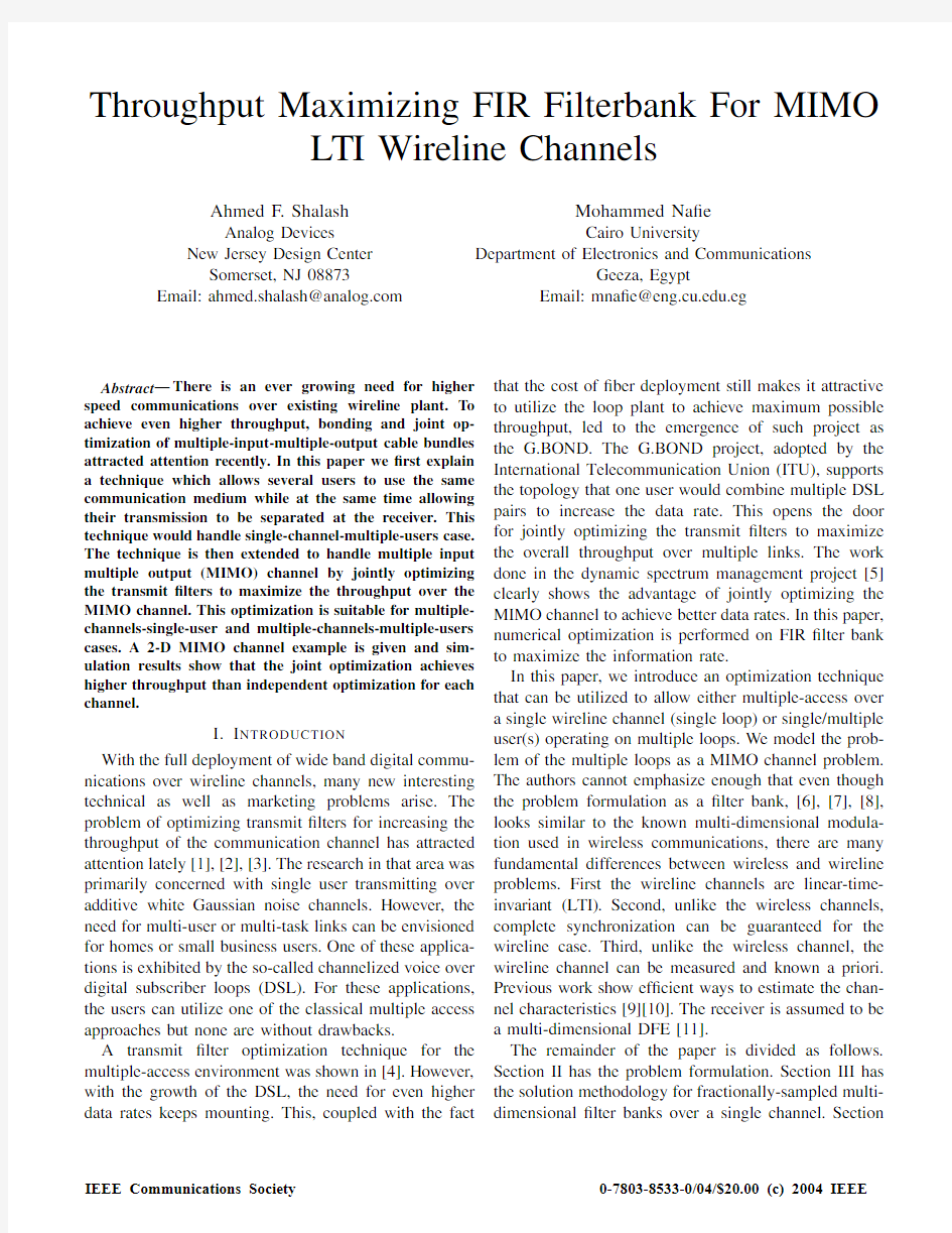
where I N+νis the identity matrix of size N+ν,()h denotes the hermitian transpose,H is the channel matrix whose?rst block-row is equal to the(ν+1)length chan-nel impulse response appended by zeros,and R nn and R xx denote the Toeplitz auto-correlation matrices for the noise and the input sequences,respectively.The channel throughput can be maximized by numerically solving the constrained and nonlinear optimization problem using the sequential quadratic programming
algorithm[12].
stationary
noise
x(m) x(m+1) x(m+2).....x(m+N?1)
Fig.1.Operation of1-D fractionally sampled FIR transmit?lter
III.M ULTI-USER O PTIMIZATION
A.Fractional Optimization
More optimization can be achieved when the FIR ?lter is fractionally sampled instead of being symbol rate sampled.Logically,increasing the sampling rate of the FIR will increase the optimization degrees of freedom, hence allowing increase in the channel throughput.The throughput function can be written as in(3),except that now
R xx=P?R uu?P h(4) where P is a matrix corresponding to the fractionally spaced transmit?lter to be optimized,and u is the oversampled input bit sequence.Therefore R uu will be a diagonal matrix,with zeros everywhere except in the positions corresponding to symbols.Figure1shows the operation of the1-D fractionally sampled FIR?lter. As an example,the optimization was performed on the linear channel given by
h(z)=0.1+0.3z?1+0.5z?2.(5) The resulting information rates for different SNR are plotted in Figure2.As shown in the?gure,the fractional optimization gives a consistent throughput improvement compared to the popular raised-cosine signal[4].
B.Multi-Dimensional Signaling
Up until now,most of the research in multiuser communications has focused on wireless channels.Many of the ideas developed for wireless mediums cannot be carried over to wireline communications.An obvious way to see this is that,in wireless communications, each user has their own channel characteristics while in wireline they all share the same wire,and hence the same channel.Second,the wireline channel,prac-tically,is not time-varying and synchronization can be easily achieved between different users.The optimization
Fig.2.Throughput for fractionally sampled transmit?lters
Fig.3.The advantage of the optimized signaling compared to the time division multiple access
technique explained above can be used to generate1-dimensional FIR signal.To be able to accommodate multiple users over the same channel,an increase in the system dimensionality has to be made.We propose two ways for obtaining the multi-dimensional FIR?lters. First,direct optimization with a modi?cation to equa-tion(3)can be performed.Speci?cally,and since we assume independent users
R xx=
i P i R u
i u i
P h i(6)
where P i and R u
i u i are,respectively,the transmit?lter
matrix and the autocorrelation function of user i.This technique will outperform the time division multiplexing from information rate view point.Figure3shows the advantage of using the optimization multi-dimensional FIR transmit?lters over the time multiplexed single transmit?lter.The other technique offers?exibility in the signals generation and allows incremental addition of users and easier receiver equalization.We use the frequency response of the FIR?lter as a template and employ the signal generation technique explained in[13] to incrementally generate any required number of sig-nals.The optimization problem is stated mathematically as?nding
min
{f i}
{max(|F i?R|)}
s.t.f i is orthogonal to f j,j where F i is the frequency characteristics of the?lter f i and R is the template being used.Notice that when users join the system incrementally,the original users on the system need only to change their rate such that the total rate is equal to the Nyquist rate of the usable bandwidth of the channel.The?lters are always the same no matter how many users are using the channel. IV.M ULTI-C HANNEL O PTIMIZATION The problem de?ned in the previous section can be extended to cover operating over MIMO channel.An ex-ample of2-D MIMO channel is shown in Figure4.The channel clearly resembles the known de?nition of direct connections and far end crosstalk(FEXT)connections associated with DSL environment operating in simplex mode.Only FEXT is considered in this example,how-ever the problem can easily be extended to cover full-duplex communications with near-end crosstalk(NEXT) as well.The throughput as de?ned in equation(3)can be re-de?ned to account for the crosstalk portion as I1= 1 (N+ν1) log2(|I N+ν 1 +H h1R?1n 1n1 H1R x 1x1 |)(7) I2= 1 (N+ν2) log2(|I N+ν 2 +H h2R?1n 2n2 H2R x 2x2 |),(8) Where R n 1n1 and R n 2n2 will each include the external noise term and the cross talk term.Under the assumption of independence among the signal sources and between the signal source and the noise,we can write R n 1n1 =R nn+((P2H21)h R u 2u2 P2H21)(9) R n 2n2 =R nn+((P1H12)h R u 1u1 P1H12)(10) where R nn is the external noise auto-correlation,assum-ing same noise is added to both paths,H21and H12are the cross talk channel matrices for both paths,and P1 and P2are the transmit?lter matrices. Fig.4.2-input/2-output MIMO channel A.Optimization Flavors There are many possibilities for optimization depend-ing on the particular setup.For multiple users case,we can assume same information rate for all users,i.e.fair-ness among users.This will be similar to the constraint put on the optimization performed for the single-channel-multiple-users case.If the computational complexity is of a concern,we can assume same transmit ?lter for all users,making it less computationally intensive to perform the optimization.Another setup involves,similar to the G.BOND project,that the user owns all the channels and thus we need to optimize the aggregate information rate.There are other possibilities that can be entertained and are beyond the scope of this paper.The authors intend to discuss these cases in an upcoming paper. Fig.5.The forward channel and the far end crosstalk channel B.Numerical Example Assume for simplicity that the direct channel is the same as in equation (5)and the crosstalk channel is given by h (z )=0.1?0.1z ?1?.2z ?2. (11) The direct and crosstalk channels are shown in Fig-ure 5.The optimization was performed by assuming a symmetric MIMO system (H 1=H 2and H 12=H 21)and by forcing the two ?lters P 1and P 2to be identical.This guarantees that I 1=I 2and hence can be used to guarantee fairness among different users.Even with such limitations,the jointly optimized ?lter outperforms the individually optimized ?lter as shown in Figure 6.The received signal and noise pro?les are shown in Figure 7. Fig.6.The joint optimization versus individual optimization for I 1(=I 2in this case) When the optimization is done for I 1+I 2,without con-straining I 1=I 2,even better performance can be achieved as shown in Figure 8.This case can be used,for example,when a single user is using multiple pairs and the only concern is to maximize the total throughput.It is worth noting that for high signal-to-noise ratios,the solution converges to the case where P 1=P 2and I 1=I 2.Note that the information rate in Figure 8is I 1+I 2rather than just I 1as in Figure 6.In Figure 6I 1=I 2by de?nition.C.Higher Dimensions It is straight forward to increase the dimensionality of the optimization problem.For practical DSL environ-ment,e.g.a single user owning 2-pair,or 4-pair cable,the MIMO optimization can be performed off line using a central processing unit.Notice that the optimization suitable for each case would depend on the particular Fig.7.The PSD pro?le at the y1point in Figure 4 scenario.To give a simple example of that,assume that we want to maximize the throughput of user 1who owns a 2-pair while at the same time keeping fairness between him and user 2with a 4-pair.Then you would maximize the throughput of the user 1while constraining the user 2throughput to be half per channel (or perhaps a little bit less than half)compared to user 1.As the channel is assumed to be practically LTI,then this operation needs to be performed once.For practical systems,temperature changes might contribute to channel variations.However,temperature changes are usually very slow and can be neglected for all practical purposes. Fig.8.The joint optimization of I 1+I 2when P 1and P 2are different V.C ONCLUSION In this paper,the problem of optimizing the FIR trans-mit ?lter bank was extended from a single channel envi-ronment to MIMO environment.The problem was ?rst de?ned for the single channel,fractionally sampled case.The throughput optimization was performed for multi-dimensional transmit ?lter bank over a single channel to support single-channel-multi-users case.By re-driving the throughput formula to cover the multi-channel case,the optimization can be jointly performed to maximize the overall information rate for any given MIMO chan-nels.It was shown that doing joint optimization clearly outperforms the independent “stand-alone”optimization.Even though the problem complexity would exponen-tially increase with the number of pairs,for practical DSL bonding environment,entailing two,three,or four-pair bonding,the optimization can be performed with reasonable complexity.Different ?avors of optimization can be performed to accommodate different services.These results come in line with the work performed in [5]. R EFERENCES [1]N.Al-Dhahir and J.Ciof?,“Block Transmission Over Disper-sive Channels:Transmit Filter Optimization and Realization,and MMSE-DFE Receiver Performance,”IEEE Trans.on Infor.Theory ,pp.137–160,Jan.1996. [2] A.Scaglione ,S.Barbarossa,and G.B.Giannakis,“Filterbank Transceivers Optimizing Information Rate in Block Transmis-sions over Dispersive Channels,”IEEE Trans.on Information Theory ,vol.45,pp.1019–1032,April 1999. [3]J.M.Ciof?,G.P.Dudevoir,M.V .Eyuboglu,and G.D.Forney Jr.,“MMSE decision-feedback equalizers and coding.Parts I and II,”IEEE Trans.on Comm.,pp.2582–604,Oct.1995.[4] A.F.Shalash and M.Na?e,“Multiple Access Over Digital Subscriber Loops Using Optimal FIR Transmit Filter Bank,”Globecom’99,Brazil ,1999. [5]Committee T1,Dynamic Spectrum Management Project . https://www.360docs.net/doc/4318927685.html,. [6]G.Cherubini ,E.Eleftheriou,and S.Olcer,“Filtered multitone modulation for VDSL,”Global Telecommunications Confer-ence,GLOBECOM ’99,vol.2,pp.1139–1144,Dec.1999.[7]P.P.Vaidyanathan,Multirate Systems and Filter Banks .Prentice Hall,1993. [8]T.Ihalainen,J.Alhava,A.Viholainen,X.Hongnian,J.Rinne, and M.Renfors,“On the performance of ?lter bank based multicarrier systems in xDSL and WLAN applications,”ICC 2000,vol.2,pp.1120–1124,2000. [9] C.Zeng et al.,“Crosstalk Identi?cation in XDSL Systems,” IEEE J-SAC ,vol.19,no.8,pp.1488–1496,2001. [10]S.Galli et al.,“A Frequency-Domain Approach to Crosstalk Identi?cation in xDSL Systems,”IEEE J-SAC ,vol.19,no.8,pp.1497–1506,2001. [11] A.Duel-Hallen,“Equalizers for Multiple Input/Multiple Out-put Channels and PAM Systems With Cyclostationary Input Sequences,”IEEE J-SAC ,vol.10,pp.630–639,Apr.1992.[12]Nofal Al-Dhahir,“Optimum Finite-Length LTI Transmit Filters For ISI Channels,”IEEE International Conference on Acoustics,Speech,and Signal Processing ,1998.Seatle,W A. [13] A.F.Shalash and K.K.Parhi,“Multi-Dimensional Carrierless AM/PM Systems for Digital Subscriber Loops,”IEEE https://www.360docs.net/doc/4318927685.html,m.,pp.1655–1667,Nov.1999. 实验六 用窗函数法设计 FIR 滤波器 一、实验目的 (1) 掌握用窗函数法设计FIR 数字滤波器的原理和方法。 (2) 熟悉线性相位FIR 数字滤波器特性。 (3) 了解各种窗函数对滤波特性的影响。 二、实验原理 滤波器的理想频率响应函数为H d (e j ω ),则其对应的单位脉冲响应为: h d (n) = ?-π π ωωωπ d e e H n j j d )(21 窗函数设计法的基本原理是用有限长单位脉冲响应序列h(n)逼h d (n)。由于h d (n)往往是无 限长序列,且是非因果的,所以用窗函数。w(n)将h d (n)截断,并进行加权处理: h(n) = h d (n) w(n) h(n)就作为实际设计的FIR 数字滤波器的单位脉冲响应序列,其频率响应函数H(e j ω )为: H(e j ω ) = ∑-=-1 )(N n n j e n h ω 如果要求线性相位特性,则h (n )还必须满足: )1()(n N h n h --±= 可根据具体情况选择h(n)的长度及对称性。 用窗函数法设计的滤波器性能取决于窗函数w(n)的类型及窗口长度N 的取值。设计过程中,要根据对阻带最小衰减和过渡带宽度的要求选择合适的窗函数类型和窗口长度N 。 三、实验步骤 1. 写出理想低通滤波器的传输函数和单位脉冲响应。 2. 写出用四种窗函数设计的滤波器的单位脉冲响应。 3. 用窗函数法设计一个线性相位FIR 低通滤波器,用理想低通滤波器作为逼近滤波器,截止频率ωc =π/4 rad ,选择窗函数的长度N =15,33两种情况。要求在两种窗口长度下,分别求出h(n),打印出相应的幅频特性和相频特性曲线,观察3dB 带宽和阻带衰减; 4 用其它窗函数(汉宁窗(升余弦窗)、哈明窗(改进的升余弦窗)、布莱克曼窗) 设计该滤波器,要求同1;比较四种窗函数对滤波器特性的影响。 四、实验用MATLAB 函数 可以调用MATLAB 工具箱函数fir1实现本实验所要求的线性相位FIR-DF 的设计,调用一维快速傅立叶变换函数fft 来计算滤波器的频率响应函数。 FIR 数字滤波器设计函数 1. fir1 功能:基于窗函数的FIR 数字滤波器设计——标准频率响应。 格式:b=fir1(n,Wn) b=fir1(n,Wn,'ftype') b=fir1(n,Wn,Window) b=fir1(n,Wn,'ftype',Window) 说明:fir1函数以经典方法实现加窗线性相位FIR 滤波器设计,它可设计出标准的低通、带通、高通和带阻滤波器。 b=fir1(n,Wn)可得到n 阶低通FIR 滤波器,滤波器系数包含在b 中,这可表示成: n z n b z b b z b --++???++=)1()2()1()(1 这是一个截止频率为Wn 的Hamming(汉明)加窗线性相位滤波器,0≤Wn ≤1,Wn=1相应于0.5fs 。 当Wn=[W1 W2]时,fir1函数可得到带通滤波器,其通带为W1<ω< W2。 b=fir1(n,Wn,'ftype')可设计高通和带阻滤波器,由ftype 决定: ·当ftype=high 时,设计高通FIR 滤波器; ·当ftype=stop 时,设计带阻FIR 滤波器。 在设计高通和带阻滤波器时,fir1函数总是使用阶为偶数的结构,因此当输入的阶次为奇数时,fir1函数会自动加1。这是因为对奇数阶的滤波器,其在Nyquist 频率处的频率响应为零,因此不适合于构成高通和带阻滤波器。 b=fir1(n,Wn,Window)则利用列矢量Window 中指定的窗函数进行滤波器设计,Window 长度为n+1。如果不指定Window 参数,则fir1函数采用Hamming 窗。 Blackman 布莱克曼窗 Boxcar 矩形窗 Hamming 海明窗 Hann 汉宁窗 Kaiser 凯瑟窗 Triang 三角窗 b=fir1(n,Wn,'ftype',Window)可利用ftype 和Window 参数,设计各种加窗的滤波器。 由fir1函数设计的FIR 滤波器的群延迟为n/2。 例如: n=32;wn=1/4;window=boxcar(n+1) b=fir1(n,wn,window) 电子科技大学信息与软件工程学院学院标准实验报告 (实验)课程名称数字信号处理 电子科技大学教务处制表 电 子 科 技 大 学 实 验 报 告 学生姓名: 学 号: 指导教师: 实验地点: 实验时间:14-18 一、实验室名称:计算机学院机房 二、实验项目名称:fir 低通滤波器的设计 三、实验学时: 四、实验原理: 1. FIR 滤波器 FIR 滤波器是指在有限范围内系统的单位脉冲响应h[k]仅有非零值的滤波器。M 阶FIR 滤波器的系统函数H(z)为 ()[]M k k H z h k z -==∑ 其中H(z)是k z -的M 阶多项式,在有限的z 平面内H(z)有M 个零点,在z 平面原点z=0有M 个极点. FIR 滤波器的频率响应 ()j H e Ω 为 0 ()[]M j jk k H e h k e Ω -Ω ==∑ 它的另外一种表示方法为 () ()()j j j H e H e e φΩΩΩ= 其中 () j H e Ω和()φΩ分别为系统的幅度响应和相位响应。 若系统的相位响应()φΩ满足下面的条件 ()φαΩ=-Ω 即系统的群延迟是一个与Ω没有关系的常数α,称为系统H(z)具有严格线性相位。由于严格线性相位条件在数学层面上处理起来较为困难,因此在FIR 滤波器设计中一般使用广义线性相位。 如果一个离散系统的频率响应 ()j H e Ω 可以表示为 ()()()j j H e A e αβΩ-Ω+=Ω 其中α和β是与Ω无关联的常数,()A Ω是可正可负的实函数,则称系统是广义线性相位的。 如果M 阶FIR 滤波器的单位脉冲响应h[k]是实数,则可以证明系统是线性相位的充要条件为 [][]h k h M k =±- 当h[k]满足h[k]=h[M-k],称h[k]偶对称。当h[k]满足h[k]=-h[M-k],称h[k]奇对称。按阶数h[k]又可分为M 奇数和M 偶数,所以线性相位的FIR 滤波器可以有四种类型。 2. 窗函数法设计FIR 滤波器 窗函数设计法又称为傅里叶级数法。这种方法首先给出()j d H e Ω, ()j d H e Ω 表示要逼近的理想滤波器的频率响应,则由IDTFT 可得出滤波器的单位脉冲响应为 1 []()2j jk d d h k H e e d π π π ΩΩ-= Ω ? 由于是理想滤波器,故 []d h k 是无限长序列。但是我们所要设计的FIR 滤波 器,其h[k]是有限长的。为了能用FIR 滤波器近似理想滤波器,需将理想滤波器的无线长单位脉冲响应 []d h k 分别从左右进行截断。 当截断后的单位脉冲响应 []d h k 不是因果系统的时候,可将其右移从而获得因果的FIR 滤波器。 1.课题描述......................................................... (1) 2.题目及要求......................................................... (1) 3.设计原理......................................................... (1) 3.1 滤波器的分类......................................................... (1) 3.2 数字滤波器工作原理 (1) 3.3 FIR滤波器的设计指 标 (3) 3.4窗函数设计FIR滤波器的设计原 理 (5) 3.5用窗函数设计滤波器的步 骤 (10) 3.6实验所用MATLAB函数说 数 (11) 4设计容......................................................... (12) 4.1用MATLAB编程实 现 (12) 4.2结果分析......................................................... (15) 5总结......................................................... (17) 6参考文献......................................................... (17) 1.课题描述 数字滤波器是指输入、输出均为数字信号,通过数值运算处理改变输入信号所含频率成分的相对比例,或者滤除某些频率成分的数字器件或程序。因此,数字滤波的概念和模拟滤波相同,只是信号的形成和实现滤波方法不同。正因为数字滤波通过数值运算实现滤波,所以数字滤波处理精度高、稳定、体积小、质量轻、灵活、不存在阻抗匹配问题,可以实验模拟滤波器无法实现的特殊滤波功能。本课题使用MATLAB信号处理箱和运用窗函数的FIR滤波器去除无用信号。2.题目及要求 产生包含三个正弦成分(120hz,80hz,20hz)的信号,设计基于窗函数的FIR滤波器去除120hz,20hz成分,保留80hz信号。通带允许的最大衰减为0.25dB,阻带应达到的最小衰减为20dB。滤波器的采样频率为500Hz。 3.设计原理 3.1滤波器的分类 从功能上可以分为:低通、高通、带通和带阻。 从处理信号分为:经典滤波器和现代滤波器。 从设计方法上分为:切比雪夫和巴特沃斯 从实现方法上分为:FIR和IIR 3.2数字滤波器的工作原理 数字滤波器是一个离散时间系统,输入x(n)是一个时间序列,输出y(n)也是一个时间序列。如数字滤波器的系统函数为H(Z),其脉 实验报告 课程名称:数字信号处理指导老师:刘英成绩:_________________实验名称: FIR数字滤波器设计与使用同组学生姓名:__________ 一、实验目的和要求 设计和应用FIR低通滤波器。掌握FIR数字滤波器的窗函数设计法,了解设计参数(窗型、窗长)的影响。 二、实验内容和步骤 编写MATLAB程序,完成以下工作。 2-1 设计两个FIR低通滤波器,截止频率 C =0.5。 (1)用矩形窗,窗长N=41。得出第一个滤波器的单位抽样响应序列h 1(n)。记下h 1 (n) 的各个抽样值,显示h 1 (n)的图形(用stem(.))。求出该滤波器的频率响应(的N 个抽样)H 1(k),显示|H 1 (k)|的图形(用plot(.))。 (2)用汉明窗,窗长N=41。得出第二个滤波器的单位抽样响应序列h 2(n)。记下h 2 (n) 的各个抽样值,显示h 2(n)的图形。求出滤波器的频率响应H 2 (k),显示|H 2 (k)|的 图形。 (3)由图形,比较h 1(n)与h 2 (n)的差异,|H 1 (k)|与|H 2 (k)|的差异。 2-2 产生长度为200点、均值为零的随机信号序列x(n)(用rand(1,200)0.5)。显示x(n)。 求出并显示其幅度谱|X(k)|,观察特征。 2-3 滤波 (1)将x(n)作为输入,经过第一个滤波器后的输出序列记为y 1(n),其幅度谱记为|Y 1 (k)|。 显示|X(k)|与|Y 1 (k)|,讨论滤波前后信号的频谱特征。 (2)将x(n)作为输入,经过第二个滤波器后的输出序列记为y 2(n),其幅度谱记为|Y 2 (k)|。 比较|Y 1(k)|与|Y 2 (k)|的图形,讨论不同的窗函数设计出的滤波器的滤波效果。 2-4 设计第三个FIR低通滤波器,截止频率 C =0.5。用矩形窗,窗长N=127。用它对x(n)进行滤波。显示输出信号y 滤波器设计原理 本文将介绍数字滤波器的设计基础及用窗函数法设计FIR 滤波器的方法,运用MATLAB 语言实现了低通滤波器的设计以及用CCS软件进行滤波效果的观察。读取语音文件,并加入一定的随机噪声,最后使用窗函数滤波法进行语音滤波,将加噪后的语音文件转换为.dat文件使其能和ccs软件链接,输出个阶段的时域和频域波形。 根据数字滤波器冲激响应函数的时域特性。可将数字滤波器分为两种,即无限长冲激响应( IIR) 滤波器和有限长冲激响应(FIR) 滤波器。IIR 滤波器的特征是具有无限持续时间的冲激响应;FIR 滤波器冲激响应只能延续一定时间。其中FIR 滤波器很容易实现严格的线性相位,使信号经过处理后不产生相位失真,舍入误差小,稳定等优点。能够设计具有优良特性的多带通滤波器、微分器和希尔伯特变换器,所以在数字系统、多媒体系统中获得极其广泛的应用。FIR数字滤波器的设计方法有多种,如窗函数设计法、最优化设计和频率取样法等等。而随着MATLAB软件尤其是MATLAB 的信号处理工具箱和Simulink 仿真工具的不断完善,不仅数字滤波器的计算机辅助设计有了可能而且还可以使设计达到最优化。 FIR滤波器的窗函数法的设计 采用汉明窗设计低通FIR滤波器 使用b=fir1(n,Wn)可得到低通滤波器。其中,0Wn1,Wn=1相当于0.5。其语法格式为 b=fir1(n,Wn); 采用:b=fir1(25, 0.25); 得到归一化系数: 或者在命令行输入fdatool进入滤波器的图形设置界面,如下图所示 得到系数(并没有归一化) const int BL = 26; const int16_T B[26] = { -26, 33, 126, 207, 138, -212, -757, -1096, -652, 950, 3513, 6212, 7948, 7948, 6212, 3513, 950, -652, -1096, -757, -212, 138, 207, 126, 33, -26 }; FIR滤波器的设计(Matlab) 技术指标为:采用25阶低通滤波器,汉明窗(Hamming Window)函数,截止频率为1000Hz,采样频率为8000Hz,增益40db。 下面的程序功能是:读取语音文件,并加入一定的随机噪声,最后使用窗函数滤波法进行语音滤波,将加噪后的语音文件转换为.dat文件使其能和ccs软件链接,输出个阶段的时域和频域波形。 课题名称:FIR滤波器窗函数设计 FlR 滤波器窗函数设计 引言: 数字滤波器(DigitalFilter )是指输入、输出都是离散时间信号,通过一定运算 关系改变输入信号所含频率成分的相对比例或者滤除某些频率成分的器件。 在许 多数字信号处理系统中,如图像信号处理等,有限冲激响应( FIR )滤波器是最 常用的组件之一,它完成信号预调、频带选择和滤波等功能。 FIR 滤波器虽然在 截止频率的边沿陡峭性能上不及无限冲激响应 (IIR )滤波器,但是却具有严格的 线性相位特性,稳定性好,能设计成多通带(或多阻带)滤波器组,所以能够在 数字信号处理领域得到广泛的应用。 数字滤波器的分类 1) 根据系统响应函数的时间特性分为两类 1. FIR (Finite ImPUISe Response 数字滤波器网络 M y[n] b k x[n k] k0 特点:不存在反馈支路,其单位 冲激响应为有限长 2. IIR ( Infinite ImPUISe Response 数字滤波器网络 特点:存在反馈支路,即信号流图中存在环路,其单位冲激响应为无限长 (2) FIR 数字滤波器IIR 数字滤波器的区别 1. 从性能上来说,IlR 滤波器传递函数包括零点和极点两组可调因素, 对极点的 惟一限制是在单位圆内。因此可用较低的阶数获得高的选择性,所用的存储 单元 少,计算量小,效率高。但是这个高效率是以相位的非线性为代价的。 选择性越好,则相位非线性越严重。FIR 滤波器传递函数的极点固定在原点, 是不能动的,它只能靠改变零点位置来改变它的性能。所以要达到高的选择 性,必须用较高的阶数;对于同样的滤波器设计指标, FIR 滤波器所要求的 阶数可能比IIR 滤波器高5-10倍,但是FIR 滤波器可以得到严格的线性相位。 2. 从结构上看,IIR 滤波器必须采用递归结构,极点位置必须在单位圆内,否则 系统将 不稳定。相反,FIR 滤波器只要采用非递归结构,不论在理论上还是 在实际的有限精度运算中都不存在稳定性问题, 因此造成的频率特性误差也 较小。此外FIR 滤波器可以采用快速傅里叶变换算法, 在相同阶数的条件下, 运算速度可以快得多。 3. 从设计工具看,IIR 滤波器可以借助于模拟滤波器的成果,因此一般都有有效 的圭寸闭形式的设计公式可供准确计算,计算工作量比较小,对计算工具的要 求不高。 hn b n , 0 n M 0, 其他 n y[n] b k x[n k] k0 a k y[n k1 k] Matlab实现振动信号低通滤波 附件txt中的数字是一个实测振动信号,采样频率为5000Hz,试设计一个长度为M=32的FIR低通滤波器,截止频率为600Hz,用此滤波器对此信号进行滤波。 要求: (1)计算数字截止频率; (2)给出滤波器系数; (3)绘出原信号波形; (4)绘出滤波后的信号波形; 解答过程: 第一部分:数字截止频率的计算 数字截止频率等于截止频率除以采样频率的一半,即 n=600/5000/2=0.24第二部分:滤波器系数的确定 在matlab中输入如下程序,即可得到滤波器系数: n=32 Wn=0.24 b=fir1(n,Wn) 得到的滤波器系数b为 Columns 1 through 9 -0.0008-0.0018-0.0024-0.00140.00210.00750.01100.0077-0.0054Columns 10 through 18 -0.0242-0.0374-0.02990.00870.07560.15370.21660.24070.2166Columns 19 through 27 0.15370.07560.0087-0.0299-0.0374-0.0242-0.00540.00770.0110Columns 28 through 33 0.00750.0021-0.0014-0.0024-0.0018-0.0008 第三部分:原信号波形 将附件4中的dat文件利用识别软件读取其中的数据,共1024个点,存在TXT文档中,取名bv.txt,并复制到matlab的work文件夹。 在matlab中编写如下程序: x0=load('zhendong.txt');%找到信号数据地址并加载数据。 t=0:1/5000:1023/5000;%将数据的1024个点对应时间加载 figure(1); plot(t,x0); xlabel('t/s'); ylabel('幅值'); 运行之后就得到如下波形,即振动信号的原始波形图: 1.5 1 0.5 幅 值 实验四 窗函数法设计FIR 数字滤波器 一、实验目的 1、掌握窗函数法设计FIR 数字滤波器的原理及具体方法。 2、掌握频率取样法设计FIR 数字滤波器的原理和基本方法。 3、学习利用窗函数法和频率取样法设计低通、带通、高通、带阻数字滤波器。 二、实验环境 计算机、MATLAB 软件 三、实验基础理论 窗函数设计FIR 滤波器 1.基本原理 窗函数设计法的基本思想为,首先选择一个适当的理想的滤波器()j d H e ω ,然后 用窗函数截取它的单位脉冲响应(n)d h ,得到线性相位和因果的FIR 滤波器。这种方法的重点是选择一个合适的窗函数和理想滤波器,使设计的滤波器的单位脉冲响应逼近理想滤波器的单位脉冲响应。 2.设计步骤 (1)给定理想滤波器的频率响应()j d H e ω ,在通带上具有单位增益和线性相位, 在阻带上具有零响应。一个带宽为()c c ωωπ<的低通滤波器由下式给定: π ωωωωωωω≤<=≤=-||,0)(,||,)(c j d c ja j d e H e e H 其中α为采样延迟,其作用是为了得到一个因果系统。 (2)确定这个滤波器的单位脉冲响应 ) ()) (sin()(a n a n n h c d --= πω 为了得到一个(n)h 长度为N 的因果的线性相位FIR 滤波器,我们令 2 1 -= N a (3)用窗函数截取(n)d h 得到所设计FIR 数字滤波器:)()()(n R n h n h N d = 3.窗函数的选择 常用的窗函数有矩形(Rectangular )窗,汉宁(Hanning )窗,海明(Hamming )窗、布莱克曼(Blackman )窗、凯瑟(Kaiser )窗等 表4-1 MATLAB 中产生窗函数的命令 实验二:FIR 数字滤波器设计与软件实现 一、实验指导 1.实验目的 (1掌握用窗函数法设计 FIR 数字滤波器的原理和方法。 (2掌握用等波纹最佳逼近法设计 FIR 数字滤波器的原理和方法。 (3掌握 FIR 滤波器的快速卷积实现原理。 (4学会调用 MA TLAB 函数设计与实现 FIR 滤波器。 2. 实验内容及步骤 (1认真复习第七章中用窗函数法和等波纹最佳逼近法设计 FIR 数字滤波器的原理; (2调用信号产生函数 xtg 产生具有加性噪声的信号 xt ,并自动显示 xt 及其频谱,如图 1所示; 图 1 具有加性噪声的信号 x(t及其频谱如图 (3请设计低通滤波器,从高频噪声中提取 xt 中的单频调幅信号,要求信号幅频失真小于 0.1dB ,将噪声频谱衰减 60dB 。先观察 xt 的频谱,确定滤波器指标参数。 (4根据滤波器指标选择合适的窗函数,计算窗函数的长度 N ,调用 MATLAB 函数 fir1设计一个 FIR 低通滤波器。并编写程序,调用 MATLAB 快速卷积函数 fftfilt 实现对 xt 的滤波。绘图显示滤波器的频响特性曲线、滤波器输出信号的幅频特性图和时域波形图。 (5 重复 (3 , 滤波器指标不变, 但改用等波纹最佳逼近法, 调用MA TLAB 函数 remezord 和 remez 设计 FIR 数字滤波器。并比较两种设计方法设计的滤波器阶数。 提示:○ 1MA TLAB 函数 fir1的功能及其调用格式请查阅教材; ○ 2采样频率 Fs=1000Hz,采样周期 T=1/Fs; ○ 3根据图 1(b和实验要求,可选择滤波器指标参数:通带截止频率 fp=120Hz,阻带截 至频率 fs=150Hz, 换算成数字频率, 通带截止频率 p 20.24 p f ωπ =T=π, 通带最大衰为 0.1dB , 阻带截至频率 s 20.3 s f ωπ =T=π,阻带最小衰为 60dB 。 3、实验程序框图如图 2所示,供读者参考。 图 2 实验程序框图 4.信号产生函数 xtg 程序清单(见教材 二、滤波器参数及实验程序清单 1、滤波器参数选取 根据实验指导的提示③选择滤波器指标参数: 通带截止频率 fp=120Hz,阻带截至频率 fs=150Hz。代入采样频率 Fs=1000Hz,换算成 数字频率,通带截止频率 p 20.24 p f 用窗函数法设计FIR 数字滤波器 一、实验目的 1.掌握用窗函数法设计FIR 数字滤波器的原理和方法。 2.熟悉线性相位FIR 数字滤波器特征。 3.了解各种窗函数对滤波特性的影响。 二、实验仪器 微型计算机 matlab 软件 三、实验原理和方法 如果所希望的滤波器的理想频率响应函数为 )(ωj d e H ,则其对应的单位脉冲响应为 )(n h d =π21 ωωωππd e e H j j d )(?- (2-1) 窗函数设计法的基本原理是用有限长单位脉冲响应序列)(n h 逼近)(n h d 。由于)(n h d 往往是无限长序列,且是非因果的,所以用窗函数)(n ω将)(n h d 截断,并进行加权处理,得到: )(n h =)(n h d )(n ω (2-2) )(n h 就作为实际设计的FIR 数字滤波器的单位脉冲响应序列, 其频率响应函数)(ωj d e H 为: )(ωj d e H =∑-=-1 0)(N n j e n h ω (2-3) 式中,N 为所选窗函数)(n ω的长度。 由第七章可知,用窗函数法设计的滤波器性能取决于窗函数)(n ω的类型及窗口长度N 的取值。设计过程中,要根据对阻带最小衰减和过渡带宽度的要求选择合适的窗函数类型和窗口长度N 。各种类型的窗函数可达到的阻带最小衰减和过渡带宽度见第七章。 这样选定窗函数类型和长度N 后,求出单位脉冲响应)(n h =)(n h d ·)(n ω,并按式(2-3)求出)(ωj e H 。)(ωj e H 是否满足要求,要进行验算。一般在)(n h 尾部加零使长度满足于2的整数次幂,以便用FFT 计算)(ωj e H 。如果要观察细节,补零点数增多即可。如果)(ωj e H 不满足要求,则要重新选择窗函数类型和长度N ,再次验算,直至满足要求。 如果要求线性相位特性,则)(n h 还必须满足 )1()(n N h n h --±= (2-4) 根据上式中的正负号和长度N 的奇偶性又将线性相位FIR 滤波器分成四类。要根据设计的滤波特性正确选择其中一类。例如,要设计线性低通特征,可选择)1()(n N h n h --=一类,而不能选)1()(n N h n h ---=一类。 四、实验内容 数字信号处理课程设计 《数字信号处理》 课程设计报告 FIR数字滤波器设计及MATLAB实现 专业:通信工程 班级:通信1101班 组次:第9组 姓名及学号: 姓名及学号: 目录 一、设计目的 (3) 二、设计任务 (3) 三、设计原理 (3) 3.1窗函数法 (3) 3.2频率采样法 (4) 3.3最优化设计 (5) 3.3.1等波纹切比雪夫逼近准则 (5) 3.3.2仿真函数 (6) 四、设计过程 (7) 五、收获与体会 (13) 参考文献 (13) FIR数字滤波器设计及MATLAB实现 一、设计目的 FIR滤波器:有限长单位冲激响应滤波器,是数字信号处理系统中最基 本的元件,它可以在保证任意幅频特性的同时具有严格的线性相频特性, 同时其单位抽样响应是有限长的,因而滤波器是稳定的系统。因此,FIR 滤波器在通信、图像处理、模式识别等领域都有着广泛的应用。滤波器设 计是根据给定滤波器的频率特性,求得满足该特性的传输函数。 二、设计任务 FIR滤波器设计的任务是选择有限长度的() H e满足一定 h n,使传输函数()jw 的幅度特性和线性相位要求。由于FIR滤波器很容易实现严格的线性相位,所以FIR 数字滤波器设计的核心思想是求出有限的脉冲响应来逼近给定的频率响应。 设计过程一般包括以下三个基本问题: (1)根据实际要求确定数字滤波器性能指标; (2)用一个因果稳定的系统函数去逼近这个理想性能指标; (3)用一个有限精度的运算去实现这个传输函数。 三、设计原理 FIR滤波器设计的任务是选择有限长度的() H e满足一定 h n,使传输函数()jw 的幅度特性和线性相位要求。由于FIR滤波器很容易实现严格的线性相位,所以FIR数字滤波器设计的核心思想是求出有限的脉冲响应来逼近给定的频率响应。 设计过程一般包括以下三个基本问题: (1)根据实际要求确定数字滤波器性能指标; (2)用一个因果稳定的系统函数去逼近这个理想性能指标; (3)用一个有限精度的运算去实现这个传输函数。 3.1窗函数法 设计FIR数字滤波器的最简单的方法是窗函数法,通常也称之为傅立叶级数法。FIR数字滤波器的设计首先给出要求的理想滤波器的频率响应()jw H e,设计 d 基于matlab的FIR低通-高通-带通-带阻滤波器设计 ————————————————————————————————作者:————————————————————————————————日期: 北京师范大学 课程设计报告 课程名称: DSP 设计名称:FIR 低通、高通带通和带阻数字滤波器的设计姓名: 学号: 班级: 指导教师: 起止日期: 课程设计任务书 学生班级: 学生姓名: 学号: 设计名称: FIR 低通、高通带通和带阻数字滤波器的设计 起止日期: 指导教师: 设计目标: 1、采用Kaiser 窗设计一个低通FIR 滤波器 要求: 采样频率为8kHz ; 通带:0Hz~1kHz ,带内波动小于5%; 阻带:1.5kHz ,带内最小衰减:Rs=40dB 。 2、采用hamming 窗设计一个高通FIR 滤波器 要求: 通带截至频率wp=rad π6.0, 阻带截止频率ws=rad π4.0, 通带最大衰减dB p 25.0=α,阻带最小衰减dB s 50=α 3、采用hamming 设计一个带通滤波器 低端阻带截止频率 wls = 0.2*pi ; 低端通带截止频率 wlp = 0.35*pi ; 高端通带截止频率 whp = 0.65*pi ; 高端阻带截止频率 whs = 0.8*pi ; 4、采用Hamming 窗设计一个带阻FIR 滤波器 要求: 通带:0.35pi~0.65pi ,带内最小衰减Rs=50dB ; 阻带:0~0.2pi 和0.8pi~pi ,带内最大衰减:Rp=1dB 。 FIR 低通、高通带通和带阻数字滤波器的设计 一、 设计目的和意义 1、熟练掌握使用窗函数的设计滤波器的方法,学会设计低通、带通、带阻滤波器。 2、通过对滤波器的设计,了解几种窗函数的性能,学会针对不同的指标选择不同的窗函数。 二、 设计原理 一般,设计线性相位FIR 数字滤波器采用窗函数法或频率抽样法,本设计采用窗函数法,分别采用海明窗和凯泽窗设计带通、带阻和低通。 如果所希望的滤波器的理想频率响应函数为)(jw d e H ,如理想的低通,由信号系统的知识知道,在时域系统的冲击响应h d (n)将是无限长的,如图2、图3所示。 H d (w) -w c w c 图2 图3 若时域响应是无限长的,则不可能实现,因此需要对其截断,即设计一个FIR 滤波器频率响应∑-=-=1 0)()(N n jwn jw e n h e H 来逼近)(jw d e H ,即用一个窗函数w(n)来 截断h d (n),如式3所示: )()()(n w n h n h d = (式1)。 最简单的截断方法是矩形窗,实际操作中,直接取h d (n)的主要数据即可。 )(n h 作为实际设计的FIR 数字滤波器的单位脉冲响应序列,其频率响应函数为: ∑-=-=1 0)()(N n jwn jw e n h e H (式2) 令jw e z =,则 ∑-=-=1 0)()(N n n z n h z H (式3), 式中,N 为所选窗函数)(n w 的长度。 数字信号处理实验报告 ---实验4窗函数法设计FIR数字滤波器 一、实验目的 1.了解常用的几种窗函数,能正确选择适当的窗函数进行滤波器设计; 2.掌握窗函数法设计数字低通滤波器。 二、实验原理 1.常用的窗函数: 矩形窗函数为boxcar和rectwin,调用格式: w= boxcar(N) w= rectwin(N) 其中N是窗函数的长度,返回值w是一个N阶的向量。 三角窗函数为triang,调用格式: w= triang(N) 汉宁窗函数为hann,调用格式: w= hann(N) 海明窗函数为hamming,调用格式: w= hamming(N) 2.各个窗函数的性能比较 三、实验内容 题一:生成四种窗函数:矩形窗、三角窗、汉宁窗、海明窗,并观察其频率响应。 题二:根据下列技术指标,设计一个FIR数字低通滤波器:wp=0.2π,ws=0.4π,ap=0.25dB, as=50dB,选择一个适当的窗函数,确定单位冲激响应,绘出所设计的滤波器的幅度响应。 四、上机程序及运行结果 题一:n=30; %矩形窗及其频响 window1=rectwin(n); [h1,w1]=freqz(window1,1); subplot(4,2,1); stem(window1);title('矩形窗');subplot(4,2,2); plot(w1/pi,20*log(abs(h1))/abs(h1(1)));title('矩形窗频响'); %三角窗及其频响 window2=triang(n); [h2,w2]=freqz(window2,1); subplot(4,2,3);stem(window2);title('三角窗'); subplot(4,2,4); plot(w2/pi,20*log(abs(h2))/abs(h2(1)));title('三角窗频响'); %汉宁窗及其频响 window3=hann(n); [h3,w3]=freqz(window3,1); subplot(4,2,5);stem(window3);title('汉宁窗'); subplot(4,2,6); plot(w3/pi,20*log(abs(h3))/abs(h3(1)));title('汉宁窗频响'); %海明窗频响 window4=hamming(n); FIR 数字滤波器设计与实现 一.摘要:数字滤波器是一种具有频率选择性的离散线性系统,在信号数字处理中有着广泛的应 用。其中FIR 滤波器是一种常用的滤波器,它在保证幅度特性满足技术要求的同时,很容易做到严格的线性相位特性,在语音分析、图像处理、雷达监测等对信号相位要求高的领域有着广泛的应用,能实现IIR 滤波器不能实现的许多功能。 二.关键词:FIR 窗函数系统函数MATLAB 三.内容提要: 数字滤波器的功能就是把输入序列通过一定的运算变换成输出序列,因此数字滤波器的结构系 统中就必须包括一定数量和性能的运算器件和运算单元,而运算器件和运算单元的配置必须由数字滤波器的结构特点和性能特点来决定,因此在进行FIR 数字滤波器的设计之前,有必要介绍和总结FIR 数字滤波器的基本结构和相关特性(包括频响曲线(幅度和相位),单位冲激响应等),在介绍完其基本结构和相关特性后,就进行FIR 数字滤波器的设计和实现。 (一)FIR 滤波器的基本结构 在讨论任何一种滤波器时,都要着重分析其系统函数,FIR 滤波器的系统函数为: n N n z n h z H ∑-==1 0)()(。从该系统函数可看出,FIR 滤波器有以下特点: 1)系统的单位冲激响应h(n)在有限个n 值处不为零; 2)系统函数H(z)在|z|>0处收敛,极点全部在z=0处(稳定系统); 3)结构上主要是非递归结构,没有输出到输入的反馈,但有些结构中(例如频率抽样结构)也包 含有反馈的递归部分。 1.FIR 滤波器实现的基本结构有: 1) 横截型(卷积型、直接型) a.一般FIR 滤波器的横截型(直接型、卷积型)结构: 若给定差分方程为: 。则可以直接由差分方程得出FIR 滤波器结构如 下图所示: 这就是FIR 滤波器的横截型结构,又称直接型或卷积型结构。 b .线性相位FIR 滤波器的横截型结构 数字信号处理课程设计 设计题目半带FIR低通滤波器设计 题目编号 0205 学院名称电气学院 指导教师 班级 学号 学生姓名 目录 一.半带滤波器的概述 (1) 二.半带FIR滤波器的性质及设计方法 (1) 2.1半带FIR滤波器的性质 (1) 2.2半带滤波器的设计方法 (2) 2.3滤波器指标的确定 (3) 2.4手工计算 (4) 三.在MATLAB中仿真 (4) 3.1滤波器的系数 (4) 3.2半带FIR滤波器的频率特性曲线 (4) 3.3基于MATLAB的幅频响应曲线 (5) 四.滤波器的结构不同对性能指标的影响 (6) 4.1利用直接型结构构建滤波器 (6) 4.2利用级联型结构构建数字滤波器 (7) 五.参数字长对性能指标的影响 (8) 5.1参数字长取2位对性能指标的影响 (8) 5.2参数字长取8位对性能指标的影响 (8) 5.3参数字长取12位对性能指标的影响 (9) 5.4参数字长取14位对性能指标的影响 (9) 5.5结论 (9) 六.心得体会 (9) 七.参考文献 (10) 八.附录 (10) 半带FIR 低通滤波器的设计 一.半带滤波器的概述 在数字滤波器的设计过程中,为了能够有效地进行抽取滤波,往往采用多级抽取的方法,这就需要采用内插和抽取的原理。如果对滤波器进行M 倍抽取,则输出的采样频率是输入采样频率的I /M ;如果对滤波器进行M 倍内插,则输出的采样频率是输入采样频率的M 倍。 半带滤波器是一种基于抽取和内插原理的滤波器,它是一种特殊的低通FIR(有限冲激响应)数字滤波器——一种抽取因子为2的抽取滤波器,这种滤波器由于通带和阻带相对于二分之一Nyquist 频率对称,因而有近一半的滤波器系数为O 。由于系数为0的部分在运算的过程中不需要消耗运算量,所以运算量减少了一半,使实际滤波过程中的运算量大幅度减少。因此计算的效率高,实时性比较强,有利于滤波运算的实时实现,多速率信号处理中有着特别重要的地位,并且得到了广泛的应用。 二.半带FIR 滤波器的性质及设计方法 2.1半带FIR 滤波器的性质 图1为抽取因子为2的半带滤波器的框图,其中:)(z H h 为抽取滤波器,s f 为输入采样 率,2/1s s f f =为输出采样率。 图1 抽取因子为2的半带滤波器框图 现在考虑频率特性如图2所示的一种特殊的FIR 滤波器,即为半带FIR 滤波器,它具有如下的特性: (1)通带纹波p δ和阻带纹波s δ相等,即s p δδ=; (2)通带边频p F 和阻带边频s F 相对于4/s f 对称,即2/s s p f F F =+,用数字频率表示为:πωω=+s p 。 f s x(n) H h (z) f s 2 2/1s s f f = 《DSP技术与应用》课程设计报告 课题名称:基于DSP Builder的FIR数字滤波器的设计与实现 学院:电子信息工程学院 班级:11级电信本01班 学号: 姓名: 题目基于DSP Builder的FIR数字滤波器的设计与实现 摘要 FIR数字滤波器是数字信号处理的一个重要组成部分,由于FIR数字滤波器具有严格的线性相位,因此在信息的采集和处理过程中得到了广泛的应用。本文介绍了FIR数字滤波器的概念和线性相位的条件,分析了窗函数法、频率采样法和等波纹逼近法设计FIR滤波器的思路和流程。在分析三种设计方法原理的基础上,借助Matlab仿真软件工具箱中的fir1、fir2和remez子函数分别实现窗函数法、频率采样法和等波纹逼近法设计FIR滤波器。然后检验滤波器的滤波效果,采用一段音频进行加噪声然后用滤波器滤,对比三段音频效果进而对滤波器的滤波效果进行检验。仿真结果表明,在相频特性上,三种方法设计的FIR滤波器在通带内都具有线性相位;在幅频特性上,相比窗函数法和频率采样法,等波纹逼近法设计FIR滤波器的边界频率精确,通带和阻带衰减控制。 Abstract FIR digital filter is an important part of digital signal processing, the FIR digital filter with linear phase, so it has been widely applied in the collection and processing of information in the course of. This paper introduces the concept of FIR digital filter with linear phase conditions, analysis of the window function method and frequency sampling method and the ripple approximation method of FIR filter design ideas and processes. Based on analyzing the principle of three kinds of design methods, by means of fir1, fir2 and Remez function of Matlab simulation software in the Toolbox window function method and frequency sampling method and respectively realize equiripple approximation method to design FIR filter. Then test the filtering effect of the filter, using an audio add noise and then filter, test three audio effects and comparison of filter filtering effect. Simulation results show that the phase frequency characteristic, three design methods of FIR filter with linear phase are in the pass band; the amplitude frequency characteristics, compared with the window function method and frequency sampling method, equiripple approximation method Design of FIR filter with accurate boundary frequency, the passband and stopband attenuation control. 数字信号处理实验报告---实验4窗函数法设计FIR数字滤波器 一、实验目的 1.掌握用窗函数法、频率采样法设计FIR数字滤波器的原理及方法,熟悉相应的计算机编程。 2.熟悉线性相位FIR数字滤波器的幅频特性和相频特性。 3.了解各种不同窗函数对滤波器性能的影响。 二、实验原理 1.常用的窗函数: 矩形窗函数为boxcar和rectwin,调用格式: w= boxcar(N)w= rectwin(N) 其中N是窗函数的长度,返回值w是一个N阶的向量。 三角窗函数为triang,调用格式: w= triang(N) 汉宁窗函数为hann,调用格式: w= hann(N) 汉明窗函数为hamming,调用格式: w= hamming(N) 三、设计指标 (1)矩形窗设计线性相位低通滤波器(参数自主设定)。 (2)改用汉宁窗,设计参数相同的低通滤波器。 四、上机程序及运行结果 生成四种窗函数:矩形窗、三角窗、汉宁窗、海明窗,并观察其频率响应。 n=30; %矩形窗及其频响 window1=rectwin(n); [h1,w1]=freqz(window1,1); subplot(4,2,1); stem(window1);title('矩形窗');subplot(4,2,2); plot(w1/pi,20*log(abs(h1))/abs(h1(1)));title('矩形窗频响'); %三角窗及其频响 window2=triang(n); [h2,w2]=freqz(window2,1); subplot(4,2,3);stem(window2);title('三角窗'); subplot(4,2,4); plot(w2/pi,20*log(abs(h2))/abs(h2(1)));title('三角窗频响'); %汉宁窗及其频响 window3=hann(n); [h3,w3]=freqz(window3,1); subplot(4,2,5);stem(window3);title('汉宁窗'); subplot(4,2,6); plot(w3/pi,20*log(abs(h3))/abs(h3(1)));title('汉宁窗频响'); %汉明窗频响 window4=hamming(n); [h4,w4]=freqz(window4,1); subplot(4,2,7);stem(window4);title('汉明窗'); subplot(4,2,8); plot(w4/pi,20*log(abs(h4))/abs(h4(1)));title('汉明窗频响');实验六、用窗函数法设计FIR滤波器
FIR数字滤波器设计函数
fir低通滤波器设计(完整版)
窗函数设计FIR滤波器
FIR数字滤波器设计与使用
fir低通滤波器设计报告
FIR滤波器窗函数设计
fir低通滤波器matlab编程滤波前后图形
实验四 窗函数法设计FIR数字滤波器
FIR数字滤波器设计与软件实现(精)讲解学习
用窗函数法设计FIR数字滤波器
FIR数字滤波器设计及MATLAB使用要点
基于matlab的FIR低通高通带通带阻滤波器设计
窗函数法设计FIR数字滤波器
FIR数字滤波器设计与实现
半带FIR低通滤波器
FIR低通数字滤波器的设计要点
窗函数法设计FIR数字滤波器