STPS30H60CG-TR;STPS30H60CT;STPS30H60CR;STPS30H60CFP;STPS30H60CW;中文规格书,Datasheet资料
STPS30H60C
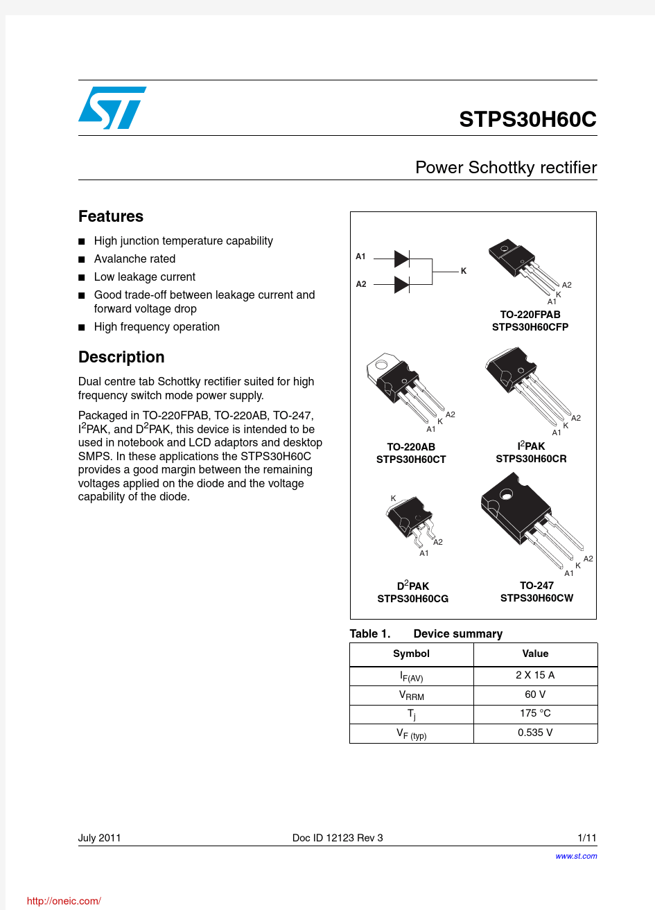
Power Schottky rectifier
Features
■ ■ ■ ■ ■
High junction temperature capability Avalanche rated Low leakage current Good trade-off between leakage current and forward voltage drop High frequency operation
A1 K A2
K A1 A2
TO-220FPAB STPS30H60CFP
Description
Dual centre tab Schottky rectifier suited for high frequency switch mode power supply. Packaged in TO-220FPAB, TO-220AB, TO-247, I2PAK, and D2PAK, this device is intended to be used in notebook and LCD adaptors and desktop SMPS. In these applications the STPS30H60C provides a good margin between the remaining voltages applied on the diode and the voltage capability of the diode.
A2 K A1 A1 K A2
TO-220AB STPS30H60CT
I2PAK STPS30H60CR
K
A2 A1 K A1 A2
D2PAK STPS30H60CG
TO-247 STPS30H60CW
Table 1.
Device summary
Symbol IF(AV) VRRM Tj VF (typ) Value 2 X 15 A 60 V 175 °C 0.535 V
July 2011
Doc ID 12123 Rev 3
1/11
https://www.360docs.net/doc/532053013.html, 11
https://www.360docs.net/doc/532053013.html,/
Characteristics
STPS30H60C
1
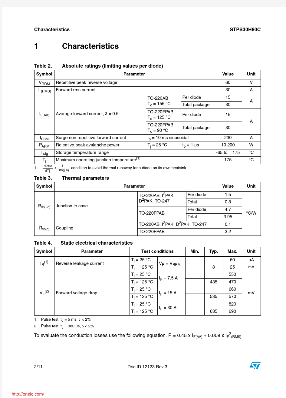
Table 2.
Symbol VRRM IF(RMS)
Characteristics
Absolute ratings (limiting values per diode)
Parameter Repetitive peak reverse voltage Forward rms current TO-220AB Tc = 155 °C IF(AV) Average forward current, δ = 0.5 TO-220FPAB Tc = 125 °C TO-220FPAB Tc = 90 °C IFSM PARM Tstg Tj Surge non repetitive forward current Releative peak avalanche power Storage temperature range Maximum operating junction temperature(1) Tj = 25 °C Per diode Total package Per diode Total package Value 60 30 15 30 15 A 30 230 10 200 -65 to + 175 175 A W °C °C Unit V A A
tp = 10 ms sinusoidal tp = 1 μs
1.
1 dPtot < condition to avoid thermal runaway for a diode on its own heatsink Rth(j-a) dTj
Table 3.
Symbol
Thermal parameters
Parameter TO-220AB, I2PAK, D2PAK, TO-247 Per diode Total Per diode Total Value 1.5 0.8 4.7 3.95 0.1 3.2 °C/W Unit
Rth(j-c)
Junction to case TO-220FPAB
Rth(c)
Coupling
TO-220AB, I2PAK, D2PAK, TO-247 TO-220FPAB
Table 4.
Symbol IR(1)
Static electrical characteristics
Parameter Reverse leakage current Test conditions Tj = 25 °C Tj = 125 °C Tj = 25 °C Tj = 125 °C Tj = 25 °C Tj = 125 °C Tj = 25 °C Tj = 125 °C VR = VRRM IF = 7.5 A IF = 15 A IF = 30 A Min. Typ. Max. 60 8 435 535 635 25 550 470 660 570 820 690 mV Unit μA
mA
VF(2)
Forward voltage drop
1. Pulse test: tp = 5 ms, δ < 2% 2. Pulse test: tp = 380 μs, δ < 2%
To evaluate the conduction losses use the following equation: P = 0.45 x IF(AV) + 0.008 x IF2(RMS)
2/11
Doc ID 12123 Rev 3
https://www.360docs.net/doc/532053013.html,/
STPS30H60C
Characteristics
Figure 1.
Conduction losses versus average forward current
Figure 2.
Average forward current versus ambient temperature (δ = 0.5, per diode)
PF(AV)(W)
12
δ=0.05 δ=0.1 δ=0.2 δ=0.5 δ=1
18 16
IF(AV)(A)
Rth(j-a)=Rth(j-c)
10
14
TO-220FPAB
8
12 10
6
8
Rth(j-a)=15 °C/W
4
T
6 4 2
2
IF(AV)(A)
0 0 2 4 6 8 10 12
δ=tp/T
14 16
tp
Tamb(°C)
0 25 50 75 100 125 150 175
0
18
Figure 3.
Normalized avalanche power derating versus pulse duration
Figure 4.
Normalized avalanche power derating versus junction temperature
1
PARM(tp) PARM(1μs)
1.2 1
PARM(Tj) PARM(25 °C)
0.1
0.8 0.6
0.01
0.4 0.2
0.001 0.01
tp(μs)
0.1 1 10 100 1000
0 25
Tj(°C)
50 75 100 125 150
Figure 5.
Non repetitive surge peak forward current versus overload duration (maximum values, per diode)
TO-220AB, TO-247 D PAK, I PAK
2 2
Figure 6.
Non repetitive surge peak forward current versus overload duration (maximum values, per diode)
TO-220FPAB
200 180 160 140 120 100 80 60 40 20
IM(A)
120
IM(A)
100
TC=50°C
80
TC=50 °C
TC=75°C
60
TC=75 °C
40
TC=125°C
IM t δ =0.5
20
IM t δ =0.5
TC=125 °C
t(s)
1.E-02 1.E-01 1.E+00
t(s)
1.E-02 1.E-01 1.E+00
0 1.E-03
0 1.E-03
Doc ID 12123 Rev 3
3/11
https://www.360docs.net/doc/532053013.html,/
Characteristics
STPS30H60C
Figure 7.
Relative variation of thermal Figure 8. impedance junction to case versus pulse duration
1.0 0.9 0.8
Relative variation of thermal impedance junction to case versus pulse duration
1.0 0.9 0.8 0.7 0.6 0.5 0.4 0.3 0.2 0.1 0.0
Zth(j-c)/Rth(j-c)
TO-220AB, TO-247 D2PAK, I2PAK
Zth(j-c)/Rth(j-c)
TO-220FPAB
δ=0.5
0.7 0.6 0.5
δ=0.5
δ=0.2 δ=0.1
0.4
T
0.3 0.2
δ=0.2 δ=0.1
T
Single pulse
tp(s)
1.E-02 1.E-01
δ=tp/T
tp
0.1
Single pulse
tp(s)
1.E-01
δ=tp/T
1.E+00
tp
0.0
1.E+00
1.E-03
1.E-03
1.E-02
1.E+01
Figure 9.
Reverse leakage current versus reverse voltage applied (typical values, per diode)
Tj=150°C
Figure 10. Junction capacitance versus reverse voltage applied (typical values, per diode)
C(nF)
10.0
F=1MHz Vosc=30mVRMS Tj=25°C
IR(mA)
1.E+02
1.E+01
Tj=125°C Tj=100°C Tj=75°C
1.E+00
1.0
1.E-01
Tj=50°C
1.E-02
Tj=25°C
1.E-03 0 5 10 15 20 25 30 35
VR(V)
40 45 50 55 60
VR(V)
0.1 1 10 100
Figure 11. Forward voltage drop versus forward current (per diode)
IFM(A)
TJ=125 °C Maximum values TJ=125 °C Typical values TJ=25 °C Maximum values
Figure 12. Thermal resistance junction to ambient versus copper surface under tab
80 70 60 50 40 30 20 10
100
Rth(j-a)(°C/W)
epoxy printed board FR4, copper thickness = 35 μm D2PAK
10
VFM(V)
1 0.0 0.1 0.2 0.3 0.4 0.5 0.6 0.7 0.8 0.9 1.0 1.1 1.2 1.3 1.4
0 0 5 10 15
S(cm2)
20 25 30 35 40
4/11
Doc ID 12123 Rev 3
https://www.360docs.net/doc/532053013.html,/
STPS30H60C
Package information
2
Package information
● ● ●
Epoxy meets UL94, V0 Cooling method: by conduction (C) Recommended torque values: – TO-220FPAB and TO-220AB 0.4 to 0.6 N·m – TO-247 0.9 to 1.2 N·m
In order to meet environmental requirements, ST offers these devices in different grades of ECOPACK? packages, depending on their level of environmental compliance. ECOPACK? specifications, grade definitions and product status are available at: https://www.360docs.net/doc/532053013.html,. ECOPACK? is an ST trademark. Table 5. TO-220FPAB dimensions
Dimensions Ref. Millimeters Min. A
A H B
Inches Min. 0.173 0.098 0.098 0.018 0.030 0.045 0.045 0.195 0.094 0.393 Max. 0.181 0.106 0.108 0.027 0.039 0.067 0.067 0.205 0.106 0.409
Max. 4.6 2.7 2.75 0.70 1 1.70 1.70 5.20 2.7 10.4
4.4 2.5 2.5 0.45 0.75 1.15 1.15 4.95 2.4 10
B D E
Dia L6 L2 L3 L5 F1 L4 F2 D L7
F F1 F2 G G1 H L2
E
16 Typ. 28.6 9.8 2.9 15.9 9.00 3.00 30.6 10.6 3.6 16.4 9.30 3.20
0.63 Typ. 1.126 0.386 0.114 0.626 0.354 0.118 1.205 0.417 0.142 0.646 0.366 0.126
F G1 G
L3 L4 L5 L6 L7 Dia.
Doc ID 12123 Rev 3
5/11
https://www.360docs.net/doc/532053013.html,/
Package information Table 6. TO-220AB dimensions
STPS30H60C
Dimensions Ref Millimeters Min. A
H2 Dia L5 L7 L6 L2 F2 F1 L9 L4 F G1 G M E D C A
Inches Min. 0.173 0.048 0.094 0.019 0.024 0.044 0.044 0.194 0.094 0.393 Max. 0.181 0.051 0.107 0.027 0.034 0.066 0.066 0.202 0.106 0.409
Max. 4.60 1.32 2.72 0.70 0.88 1.70 1.70 5.15 2.70 10.40
4.40 1.23 2.40 0.49 0.61 1.14 1.14 4.95 2.40 10
C D E F F1 F2 G G1 H2 L2 L4 L5 L6 L7 L9 M Diam.
16.4 typ. 13 2.65 15.25 6.20 3.50 14 2.95 15.75 6.60 3.93
0.645 typ. 0.511 0.104 0.600 0.244 0.137 0.551 0.116 0.620 0.259 0.154
2.6 typ. 3.75 3.85
0.102 typ. 0.147 0.151
6/11
Doc ID 12123 Rev 3
https://www.360docs.net/doc/532053013.html,/
STPS30H60C Table 7. TO-247 dimensions
Package information
Dimensions Ref Millimeters Min. A
V
Inches Min. 0.191 0.086 0.015 0.039 0.118 0.078 Typ. Max. 0.203 0.102 0.031 0.055
Typ.
Max. 5.15 2.60 0.80 1.40
4.85 2.20 0.40 1.00 3.00 2.00 2.00 3.00 10.90 15.45 19.85 3.70 18.50 14.20 34.60 5.50 2.00 5° 60° 3.55
D E
V
Dia
F F1
H
A
F2 F3
2.40 3.40
0.078 0.118 0.429
0.094 0.133
L5 L L2 L4 F1 V2 F(x3) M G E F2 F3 F4 L3 D L1
F4 G H L L1 L2 L3 L4 L5 M V V2 Dia.
15.75 0.608 20.15 0.781 4.30 0.145 0.728 14.80 0.559 1.362 0.216 3.00 0.078 5° 60° 3.65 0.139
0.620 0.793 0.169
0.582
0.118
0.143
Doc ID 12123 Rev 3
7/11
https://www.360docs.net/doc/532053013.html,/
Package information Table 8. I2PAK dimensions
STPS30H60C
Dimensions Ref. Millimeters Min.
A E L2 c2
Inches Min. Max.
Max.
A A1 b b1
4.40 2.40 0.61 1.14 0.49 1.23 8.95 2.40 4.95 10 13 3.50 1.27
4.60 2.72 0.88 1.70 0.70 1.32 9.35 2.70 5.15 10.40 14 3.93 1.40
0.173 0.094 0.024 0.044 0.019 0.048 0.352 0.094 0.195 0.394 0.512 0.138 0.050
0.181 0.107 0.035 0.067 0.028 0.052 0.368 0.106 0.203 0.409 0.551 0.155 0.055
D
c c2
L1 L b1
A1
D e e1 E
b e e1
c
L L1 L2
8/11
Doc ID 12123 Rev 3
https://www.360docs.net/doc/532053013.html,/
STPS30H60C Table 9. D2PAK dimensions
Package information
Dimensions Ref. Millimeters Min. A
A E L2
Inches Min. 0.173 0.098 0.001 0.027 0.045 0.017 0.048 0.352 0.393 0.192 0.590 0.050 0.055 0.094 Max. 0.181 0.106 0.009 0.037 0.067 0.024 0.054 0.368 0.409 0.208 0.624 0.055 0.069 0.126
Max 4.60 2.69 0.23 0.93 1.70 0.60 1.36 9.35 10.40 5.28 15.85 1.40 1.75 3.20
4.40 2.49 0.03 0.70 1.14 0.45 1.23 8.95 10.00 4.88 15.00 1.27 1.40 2.40
A1
C2
A2 B
D
L L3 A1 B2 B G A2
B2 C C2
C R
D E G L
M
*
V2
L2 L3 M R V2
* FLAT ZONE NO LESS THAN 2mm
0.40 typ. 0° 8°
0.016 typ. 0° 8°
Figure 13. Footprint (dimensions in millimeters)
16.90
10.30 1.30
5.08
8.90
3.70
Doc ID 12123 Rev 3
9/11
https://www.360docs.net/doc/532053013.html,/
Ordering information
STPS30H60C
3
Ordering information
Table 10. Ordering information
Marking STPS30H60CT STPS30H60CR STPS30H60CG Package TO-220AB I2PAK D2 PAK Weight 2.23 g 1.49 g 1.48 g 1.48 g 4.46 g 2.00 g Base qty 50 50 50 1000 30 50 Delivery mode Tube Tube Tube Tape and reel Tube Tube
Order code STPS30H60CT STPS30H60CR STPS30H60CG
STPS30H60CG-TR STPS30H60CG-TR STPS30H60CW STPS30H60CFP STPS30H60W STPS30H60CFP
D2PAK TO-247 TO-220FPAB
4
Revision history
Table 11.
Date 27-Feb-2006 31-Mar-2007 08-Jul-2011
Document revision history
Revision 1 2 3 First issue. Added TO-220FPAB package. Updated thermal parameters in Table 2. Updated Table 2. Changes
10/11
Doc ID 12123 Rev 3
https://www.360docs.net/doc/532053013.html,/
分销商库存信息:
STM STPS30H60CG-TR STPS30H60CFP STPS30H60CT STPS30H60CW STPS30H60CR STPS30H60CG