MAX4206EVKIT中文资料

General Description
The MAX4206 evaluation kit (EV kit) is a fully assembled and tested surface-mount circuit board that demon-strates the MAX4206 logarithmic amplifier. The MAX4206computes the log ratio of an input current relative to a reference current and provides a corresponding voltage output with a default 0.25V/decade scale factor. The EV kit operates from a single +2.7V to +11V supply or from dual ±2.7V to ±5.5V supplies, with the ability to select one of four reference currents.
The MAX4206 EV kit can be used to evaluate the MAX4207 by changing the IC and the input RC networks R1, R2, C7, and C8.
Features
?+2.7V to +11V Single-Supply Operation or ±2.7V to ±5.5V Dual-Supply Operation ?Selectable 10nA/100nA/1μA/10μA On-Board Reference Current ?Adjustable Output Scale Factor ?Surface-Mount Construction ?Fully Assembled and Tested
Evaluates: MAX4206/MAX4207
MAX4206 Evaluation Kit
________________________________________________________________Maxim Integrated Products 1
19-3397; Rev 0; 8/04
For pricing, delivery, and ordering information,please contact Maxim/Dallas Direct!at 1-888-629-4642, or visit Maxim’s website at https://www.360docs.net/doc/592112676.html,.
Ordering Information
Note:To evaluate the MAX4207, order a MAX4207ETE free sample with the MAX4206EVKIT.
E v a l u a t e s : M A X 4206/M A X 4207
Quick Start
The MAX4206 EV kit is a fully assembled and tested surface-mount board. Follow the steps below for board operation. Do not turn on the power supply until all connections are complete.
Recommended Equipment
?Current source capable of sourcing 10nA to 1mA current
?
Single +2.7V to +11V, 20mA DC power supply
Evaluating the MAX4206 with
Single Supply
1)Verify that shunts are connected across jumpers
JU1 and JU11 (single-supply operation, sets CMVIN = CMVOUT).
2)Verify that shunts are connected across jumpers
JU4 (pins 1 and 4), JU5 (pins 2 and 3), JU6, and JU7 (pins 1 and 2) (sets output scale factor K =1V/decade).3)Verify that shunts are connected across jumpers
JU8 (pins 2 and 3) and JU3 (pins 1 and 3) (sets on-board reference current = 100nA).
4)Verify that there is no shunt across jumpers JU2,
JU9, and JU10.5)Connect a +5V power supply to the VCC pad.
Connect the power-supply ground to the GND pad.
6)Connect a 100μA current source to the LOGIIN pad.7)Turn on the power supply and verify the output volt-ages LOGV1 = 0.75V and LOGV2 = 3.00V.
Note:For dual-supply operation, JU1 should be open.Reset the V CC and V DD to within operation range.
Detailed Description
Jumper Selection
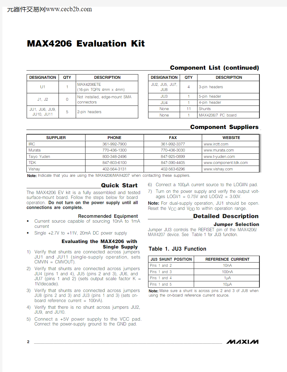
Jumper JU3 controls the REFISET pin of the MAX4206/MAX4207 device. See Table 1 for JU3 function.
MAX4206 Evaluation Kit 2_______________________________________________________________________________________
Component List (continued)
the output scale factor. See Tables 2 and 3 for setting the output scale factor for the MAX4206 and MAX4207. Jumper JU8 controls the REFIIN pin of the MAX4206/ MAX4207 device. See Table4 for JU8 function.
The EV kit incorporates jumper JU11 to create a con-nection between CMVIN and CMVOUT pins. To set the common-mode voltage input to a voltage other than 0.5V (MAX4206) or 0V (MAX4207), remove the shunt across JU11, and then connect a desired common-mode voltage on the CMVIN pad.
Output Offset (MAX4206)
To adjust the output offset voltage for single-supply operation, cut open the short on R14, install a resistor on the R14 pads, and then apply a current on the OSADJ pad. The value of R14 can be calculated by the following equation:
R14 = V
OS/ I OSADJ
where V OS is the desired offset voltage, and I OSADJ is a user-supplied offset current.To evaluate the MAX4207 with the MAX4206 EV kit, replace the MAX4206ETE with a MAX4207ETE, replace R1, R2, C7, and C8 with component values 330?, 330?, 33pF, and 33pF, respectively.
Jumper JU1 must be open to ensure proper operation with dual supplies. Evaluates: MAX4206/MAX4207MAX4206 Evaluation Kit
_______________________________________________________________________________________3
E v a l u a t e s : M A X 4206/M A X 4207
Evaluating the MAX4207 (Dual-Supply Operation)
1)Verify that there is no shunt across jumpers JU1,
JU9, and JU10 (dual-supply operation).2)Verify that there is a shunt across JU11 (sets
CMVIN = CMVOUT).
3)Verify that shunts are connected across jumpers
JU2 (pins 2 and 3), JU4 (pins 1 and 4), JU5 (pins 1and 2), and JU7 (pins 2 and 3); and JU6 is open (sets output scale factor K = 1V/decade).
4)Verify that shunts are connected across jumpers
JU8 (pins 2 and 3) and JU3 (pins 1 and 3) (sets on-board reference current = 100nA).5)Connect a +5V power supply to the VCC pad.
Connect the power-supply ground to the GND pad.Connect a -5V power supply to the VEE pad.
6)Connect a 100μA current source to the LOGIIN pad.7)Turn on the power supply and verify the output volt-ages LOGV1 = -0.75V and LOGV2 = 3.00V.
Output Offset Adjustment (MAX4207)
The MAX4207 accepts a large output-offset voltage adjustment at the inverting configuration. To adjust the output offset voltage, install a resistor on R3 and poten-tiometer on R4 pads, and make sure there is a shunt across JU2 (pins 1 and 2). The magnitude of the offset voltage is given by the following equation:
V OS = REFOUT x (R4 / (R3 + R4)) x (1 + R COMB / R6)where V OS is the desired offset voltage, and R COMB is the effective resistance between the LOGV2 and SCALE pins.
MAX4206 Evaluation Kit 4_______________________________________________________________________________________
Evaluates: MAX4206/MAX4207MAX4206 Evaluation Kit Figure 1. MAX4206 EV Kit Schematic
_______________________________________________________________________________________5
Maxim cannot assume responsibility for use of any circuitry other than circuitry entirely embodied in a Maxim product. No circuit patent licenses are implied. Maxim reserves the right to change the circuitry and specifications without notice at any time.
6_____________________Maxim Integrated Products, 120 San Gabriel Drive, Sunnyvale, CA 94086 408-737-7600?2004 Maxim Integrated Products
Printed USA
is a registered trademark of Maxim Integrated Products.
E v a l u a t e s : M A X 4206/M A X 4207
MAX4206 Evaluation Kit
Component Side
Figure 3. MAX4206 EV Kit PC Board Layout—Component Side
Figure 4. MAX4206 EV Kit PC Board Layout—Solder Side