Performance degradation of coded-OFDM due to phase noise
Performance Degradation of Coded-OFDM due to
Phase Noise
Denis Petrovic,Wolfgang Rave,Gerhard Fettweis
Technische Universit¨a t Dresden,V odafone Chair Mobile Communications Systems,D-01062Dresden,Germany Email:petrovic@ifn.et.tu-dresden.de,Phone:+4935146334958,Fax:+4935146337255
Abstract—In this paper we investigate the effect of phase noise on coded OFDM transmission with parameters typical for present OFDM based WLAN standards.Two different scenarios are compared,namely when the local oscillator at the receiver is realized as a free running oscillator or as a PLL.System performance is evaluated as a degradation of the effective SINR, using BER simulations and in terms of achievable cut-off rate for different M-QAM OFDM schemes in the presence of the phase noise.
I.I NTRODUCTION
Because of its advantages e.g.to combat ef?ciently the channel multipath,OFDM is considered as one of the most attractive transmission techniques for future wireless multime-dia communications in frequency selective channels.It yields however some disadvantages too,one being an increased sensitivity to phase noise,which is generated in the oscillators. An oscillator is a system that generates a periodic signal with a speci?ed or controllable frequency.Electronic com-ponent noise within the oscillator affects the shape of the oscillator output signal whose phase then deviates from the phase of the desired signal.
This parasitic phase modulation of the oscillator signal spreads the ideally perfect line spectrum of an oscillator.If such an oscillator is used at the receiver to down-convert the received signal at radio frequency(RF)-which in the frequency domain means nothing else than convolving the OFDM line spectrum with the non-ideal oscillator spectrum -power of each subcarrier in the down-converted OFDM spectrum spills to neighboring frequencies causing intercarrier interference.Thus the most valuable feature of OFDM,orthog-onality between the carriers is threatened by the presence of phase noise in oscillators.
There are two possibilities to realize the local oscillator (LO):to tune it to the carrier frequency(free running oscilla-tor)and to phase lock it to the carrier(receiver with PLL). In this paper we consider the in?uence of phase noise on a coded OFDM system.Section II describes the C-OFDM system model.In Section III we identify error terms in the demodulated OFDM signal due to phase noise,the model of which is given for both LO realizations in section IV.In section V the system performance is evaluated as a degradation of the effective signal-to-noise ratio due to phase noise,in terms of BER simulations and by calculation of the cut-off rate.
II.S YSTEM M ODEL
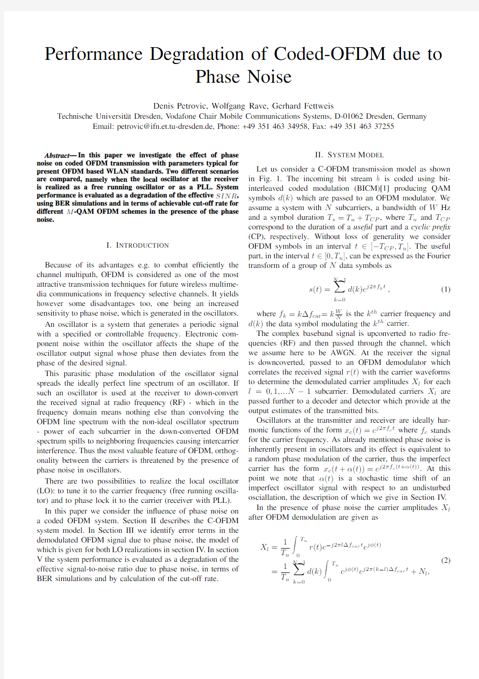
Let us consider a C-OFDM transmission model as shown in Fig. 1.The incoming bit stream b is coded using bit-interleaved coded modulation(BICM)[1]producing QAM symbols d(k)which are passed to an OFDM modulator.We assume a system with N subcarriers,a bandwidth of W Hz and a symbol duration T s=T u+T CP,where T u and T CP correspond to the duration of a useful part and a cyclic pre?x (CP),respectively.Without loss of generality we consider OFDM symbols in an interval t∈[?T CP,T u].The useful part,in the interval t∈[0,T u],can be expressed as the Fourier transform of a group of N data symbols as
s(t)=
N?1
k=0
d(k)e j2πf k t,(1)
where f k=k?f car=k W
N
is the k th carrier frequency and d(k)the data symbol modulating the k th carrier.
The complex baseband signal is upconverted to radio fre-quencies(RF)and then passed through the channel,which we assume here to be AWGN.At the receiver the signal is downcoverted,passed to an OFDM demodulator which correlates the received signal r(t)with the carrier waveforms to determine the demodulated carrier amplitudes X l for each l=0,1,...N?1subcarrier.Demodulated carriers X l are passed further to a decoder and detector which provide at the output estimates of the transmitted bits.
Oscillators at the transmitter and receiver are ideally har-monic functions of the form x c(t)=e j2πf c t where f c stands for the carrier frequency.As already mentioned phase noise is inherently present in oscillators and its effect is equivalent to a random phase modulation of the carrier,thus the imperfect carrier has the form x c(t+α(t))=e j2πf c(t+α(t)).At this point we note thatα(t)is a stochastic time shift of an imperfect oscillator signal with respect to an undisturbed osciallation,the description of which we give in Section IV. In the presence of phase noise the carrier amplitudes X l after OFDM demodulation are given as
X l=
1
T u
T u
r(t)e?j2πl?f car t e jφ(t)
=
1
T u
N?1
k=0
d(k) T u0e jφ(t)e j2π(k?l)?f car t+N l,(2)
Upconversion
Fig.1.OFDM transmission block diagram.
whereφ(t)represents the phase difference between the receiver local oscillator(LO)phase and the transmit oscillator phase,and is given by(see also Fig.1)
φ(t)=2πf c(αLO(t)?αUP(t)).(3) N l is the additive gaussian noise on subcarrier l.
III.P HASE N OISE E FFECTS ON THE Q UALITY OF OFDM
THE S IGNAL
Linearizing(2)by taking e jφ(t) 1+jφ(t)as it is done in[2],the demodulated symbol X l equals the desired symbol affected by the additive channel noise N l plus a corruption due to phase noise which can be split into two terms,namely a common phase error(CPE)and intercarrier interference (ICI)[2]
X l=d(l)+
j
T u
d(l) T u0φ(t)dt
CP E
+
1
T u
N?1
k=0,k=l
d(k) T u0φ(t)e j2π(k?l)?f car t dt
ICI
+N l
(4)
In the sequel we assume that the CPE part can be removed
when for instance pilot symbol assisted modulation[2]is used.
Thus the only relevant factor is the ICI term and its in?uence
on OFDM performance.
This ICI term is a random variable obtained as a sum of
the products of all transmitted symbols(except the desired one)and factors of the form T u0φ(t)e j2π(k?l)?f cart dt.This latter operation can be considered as an integrate and dump
?lter[3]applied to frequency-shifted versions of the phase
difference between LO and transmitter oscillator phase(see
Eq.3).Furthermore it can be shown[3],that the second
moment of the ICI term is
P ICI=P signal +∞?∞W ICI(f)Sφ(f)df(5)
where P signal corresponds to the average power of trans-
mitted symbols d(k)and Sφ(f)is the power spectral den-sity associated with the random processφ(t).W ICI(f)de-notes a weighting function for intercarrier interference and
is calculated as W ICI(f)= k=l sinc2(f/?f car?(k?l)). Note that the weighting function depends only on the sub-
carrier spacing?f car and can be well approximated by
W ICI(f)≈1?sinc2(f/?f car).
For OFDM transmission over AWGN channel we can de?ne
an effective signal-to-noise(+interference)ratio(SINR)after
OFDM demodulation for l th carrier as:
(
S
N+I
)l=
P signal
σ2n+P ICI
(6)
whereσ2n represents the AWGN noise power after OFDM de-modulation.We refer to SNR0=P signal/σ2n as the reference signal to noise ratio when no phase noise is present.
IV.P HASE N OISE M ODEL
As seen in Eq.4the processφ(t)at the output of a mixer is the one affecting the system performance.φ(t)is given by Eq.3and its statistical properties depend on the properties of αUP(t)andαLO(t)or in other words on the way in which the oscillator at the transmitter(upconversion oscillator)and local oscillator(LO)are realized.We will consider two scenarios, where in both cases the upconversion oscillator is realized as a free-running oscillator while the LO is realized as A)a free-running oscillator or B)using a PLL.
A.LO Realized as a Free-running Oscillator
In this scenario both upconversion and LO are free-running oscillators.To describe the phase noise process of a free-running(open-loop oscillator),we use the phase noise model introduced by Demir et al.[4].This theory is valid for any open-loop oscillator regardless of its operating mechanism. It is found in[4]that in this caseα(t)is asymptotically, for large t,a Wiener process,the variance of which increases linearly with time t at some rate c which depends on the oscillator quality.In other wordsα(t)=√cB(t),where B(t) stands for the Wiener process(Brownian motion).Therefore the term c suf?ces to completely characterize the phase noise process of a free-running oscillator.
In practice,however,c is not directly available.Instead,a measure used to describe oscillator performance is the decay of the oscillator power spectral density around the?rst harmonic L(f m)[dBc/Hz][2][4],where f m is the frequency offset with respect to the carrier frequency.
The connection between L(f m)and c is achieved through the3dB bandwidth?f3dB of L(f m).?f3dB can be obtained from the measured data of L(f m)which is widely available and c can then be calculated from?f3dB as c=?f3dB/πf2c [4]where f c denotes oscillator(carrier)frequency.
Let us now assume that the phase noise process of the open-loop oscillator acting as LO,denoted asαOLO(t),is character-ized with some constant c OLO.Its output is directly applied to one of the mixer’s inputs.Further assume that the phase noise
process of the upconversion oscillator αUP (t)is characterized by a constant c UP .It is sensible to assume that αOLO (t)and αUP (t)are independent.In this case the resulting process φ(t )given by Eq.3is like αOLO (t)and αUP (t)a Wiener process,speci?cally φFREE (t)=2πf c √c UP +c OLO B(t).B.LO Realized using PLL
More often,however a phase locked loop (PLL)is used at the receiver to track the reference signal phase which is in this case the phase of an upconversion oscillator.The upconversion oscillator is an open-loop oscillator characterized by c UP .The core of the PLL is an oscillator realized as a voltage controlled oscillator (VCO).We take that its phase noise process is characterized by a constant c VCO if the oscillator is operating in open-loop mode.When a PLL is operating,the phase of the VCO signal (2πf c αVCO (t)),which at the same time is output signal of the PLL,is compared with the hopefully low noise reference signal (2πf c αUP (t))and the difference of the two phases is low-pass ?ltered and applied to the controlling node of the VCO (see Fig.2).Now the PLL output signal,acting as the LO signal,is applied to the one of the mixers inputs.If the PLL is locked,the phase difference between the PLL output signal and the reference signal,denoted as φPLL (t),is very small.It is found in [5]that this process is an Ornstein-Uhlenbeck process [6]dependent on the phase noise process of the reference signal,the VCO phase noise when the VCO is operating in open-loop mode and macroscopic ?lter parameters such as ?lter order,?lter cut-off frequency and phase detector gain.
Reference Output Fig.2.Phase locked loop (PLL)block diagram.
Coming back to the problem at hand,the SINR calculation for both scenarios requires knowledge of the power spectral density of the phase noise difference process φ(t ).
As already seen φFREE (t)is a Wiener process.This process is a non-stationary stochastic process whose variance mono-tonically increases with time.The power spectrum of such process is not de?ned.An expression that is often used in the literature has the form of 1/f 2noise [7]which approximates well the phase noise ”spectrum”for frequencies not close to f =0.For the double sided power spectral density we have:
S φFREE (f )=
f 2c (c OLO +c UP )
f 2
(7)
where c OLO and c UP are de?ned as before and f c is the oscillator (carrier)frequency.
This expression however cannot be the power spectral density of a well de?ned stochastic process,because of the
in?nite variance.We will however adopt this model and justify its use later.
On the other hand when a PLL is used and we assume that the PLL is locked,φPLL (t)is asymptotically (for large t )a wide sense stationary random process with bounded variance whose double sided power spectral density is given as
S φPLL (f )=8π2f 2
c
1+o lpf
i =1
λi νi
λi +(2πf )
(8)
where o lpf is the order of the low-pass ?lter within the
PLL,while λi and νi are parameters depending on the phase noise process of the reference signal,the VCO phase noise and macroscopic PLL parameters [5].
One way to justify use of Eq.7to describe the ”power spectrum”of φFREE (t),even though it is not de?ned for frequency f =0,is to calculate the power of the ICI factor using https://www.360docs.net/doc/514611132.html,ing Eq.5and Eq.7after some manipulation gives
P ICI =
P signal π?f 3dB ?f car
+∞?∞1?sinc 2(t)
t dt (9)where ?f 3dB =πf 2
c
(c OLO +c UP )represents the 3dB bandwidth of the Wiener process.Note that the numerator of the integrand has a second-order zero which cancels the second order pole of the Wiener power spectrum,thus the ambiguity of the adopted Wiener spectrum for f =0creates no problem when calculating P ICI .It is worthwhile noting that the power of the ICI term linearly depends on the ratio ?f 3dB /?f car .Consequently for further consideration we take this relative phase noise bandwidth as a parameter describing the amount of the phase noise present in the system.
Our objective is to investigate the phase noise effect on an OFDM system with parameters typical for today’s OFDM based wireless LAN standards (e.g.IEEE802.11a [9]).We now de?ne a set of parameters which we use throughout the text unless otherwise stated.The RF car-rier frequency used is f c =5.25GHz with a subcarrier spacing of ?f car =312.5kHz.We further assume a VCO speci?cation at the receiver typical for these appli-cations [8]namely L (10kHz)=?66.5dBc/Hz which cor-responds to ?f 3dB ,VCO =70Hz and c VCO =8.2·10?19.The quality of the reference signal is typically much bet-ter,for example L (10kHz)=?135dBc/Hz corresponding to ?f 3dB ,UP 1Hz and c UP =1·10?25.When used,the PLL bandwidth is chosen to be B PLL =50kHz.
For these parameters,Fig.3plots spectra of φFREE (t)and φPLL (t).We also assume that no low pass ?lter in the PLL is used.For this case o lpf =0,λ1=B PLL and ν1=(c UP +c VCO )/2B PLL [5].
V.S YSTEM P ERFORMANCE IN T HE P RESENCE OF P HASE
N OISE A.SNR Degradation
As already discussed SINR depends not only on the shape of the phase noise spectrum but also on the carrier
Frequency [Hz]
P h a s e n o i s e s p e c t r a [d B ]
1
W ICI (f)
0.5
Fig.3.Phase noise spectrum of different oscillators.
spacing.In Fig.3we see that the spectrum of φ(t )strongly depends on the fact whether the LO is realized as a free-running oscillator or using a PLL.Note that the spectrum of φPLL (t)is basically a low-pass ?ltered version of the spectrum of φFREE (t).In the same ?gure we have also plotted the weighting function.If in a thought experiment we try to calculate the interference power given by Eq.5we see that the weighting function weights the low frequency portion of the phase noise spectrum with very small values,while for frequencies larger than the subcarrier spacing the phase noise spectrum is weighted with one.Therefore it looks that the weighting function spoils that what is obtained by using a PLL for the adopted system parameters.Indeed Fig.4shows SINR after OFDM demodulation for SNR 0[dB]=20dB,SNR 0[dB]=30dB and SNR 0[dB]=40dB.The independent variable in Fig.4is the phase noise bandwidth of the VCO at the receiver or more precisely the relative phase noise bandwidth ?f 3dB /?f car .For all three SNR 0values SINR is plotted for the cases when the VCO is used either as a free running oscillator or within a PLL.As expected the SINR is reduced when increasing the VCO phase noise bandwidth.On the other hand it can also be observed,that regarding performance due to phase noise there is almost no difference if a PLL is used or not as the curves with PLL lie only slightly above the ones for the free-running oscillator.Fig.4shows
also that the SNR 0gain is quickly lost with an increase of the VCO phase bandwidth.This is the consequence of the fact that P ICI is proportional to the signal power.
While the phase noise spectrum of a free-running oscillator depends directly on the oscillator quality,the spectrum of a PLL can be changed by varying the PLL parameters.However for any PLL type,the PLL affects the phase noise spectrum only up to the PLL bandwidth B PLL [5].B PLL should however be kept small enough to satisfy other system requirements [11].At any rate the greatest contribution to ICI power stems from the part of the phase noise spectrum above
the carrier spacing frequency ?f car ,where PLL has little or no in?uence on the spectrum.The advantage of using a PLL however,lies in the fact that it shapes the phase noise spectrum at low frequencies which determines the amount of the CPE [3]power which we assumed so far to be ideally cancelled.The phase of a free running oscillator can freely drift away from the reference signal phase thus the mean φFREE (t),which is equivalent to the correction of the common phase error,can take virtually any value for one OFDM symbol.On the other hand a PLL is tracking the phase of an input signal so φPLL (t)will oscillate around zero.We remember that φPLL (t)is an Ornstein-Uhlenbeck process which has the tendency of ”coming back”when the process drifts away from zero.Thus considering phase noise in the context of OFDM,a PLL can rather be seen as a CPE ?lter.In this regard different PLL topologies e.g.charge pump PLL [5][12]can be further used to diminish the in?uence of CPE.
Fig. 4.SNR degradation as a function of relative VCO phase noise bandwidth.
B.Bit Error Rates for AWGN Channel with Phase Noise Bit error rate curves for coded 16-QAM OFDM transmis-sion with phase noise were obtained using BICM based on convolutional coding with a standard 64-state,rate r =1/2,convolutional coder,and assuming the CPE term was com-pensated for.Fig.5compares the system performance when no phase noise is present,with the cases when phase noise is present and the low-quality VCO at the receiver is used as a free running oscillator and within a PLL.Simulations were done for a set of VCO phase noise bandwidths corresponding to ?f 3dB /?f car ∈{0.016,0.024,0.032,0.048,0.064}.The results are somewhat surprising for ?f 3dB /?f car >0.016due to a better performance in the case when LO is realized using PLL,which is not expected considering our SINR analysis.The SINR analysis is done by considering the spec-tral characteristics of the stochastic processes φPLL (t)and φFREE (t),and not only one realization of the process in a limited time.It has already been said that if PLL is used
φPLL (t)oscillates around zero while φFREE (t)can drift freely away.If the quality of a VCO oscillator is low the phase of a free-running oscillator can even within OFDM symbol duration drift away,while the PLL is trying to track the phase of an input signal thus not allowing the phase drift as much as in the free-running case.On the other hand CPE correction removes the mean of the phase noise realization within one OFDM symbol.It can be expected that when a free-running oscillator is used the phase departure from the mean value within a single OFDM symbol is bigger compared with the case when a PLL is used,thus creating bigger effective interference.This explains the difference in the performance obtained by simulations.SINR degradation analysis can therefore be seen as rather optimistic for practical systems.
Fig.5.Simulation results for 16-QAM OFDM transmission
https://www.360docs.net/doc/514611132.html,rmation Theoretical Approach
As another way to characterize the system performance we have chosen the cut-off rate as a widely accepted measure of achievable rate when a ?nite complexity coding scheme is used [1].Following expressions in [1],using a Monte Carlo method,we determined the cut-off rate for the OFDM transmission over an AWGN channel in the presence of phase noise,assuming that the CPE was compensated.
In Fig.6the cut-off rate parameter degradation for different M-QAM OFDM signaling schemes over an AWGN channel as a function of ?f 3dB /?f car is plotted.This is important because new wireless standards consider using more and more signal points in a signal constellation.It is interesting to observe that for instance 256-QAM brings nothing more in capacity for ?f 3dB /?f car >0.005than 64-QAM.In modern communication systems oscillators are high quality and we should concentrate on the values of the cut-off rate near the origin of ?f 3dB /?f car .There phase noise has a much stronger in?uence on the cut-off rate of higher order constellations as this dependence gets much steeper near the origin with an increase of the signal points.
Fig. 6.Phase noise in?uence on cut-off rate for M-QAM OFDM for
SNR 0=30dB.
VI.C ONCLUSIONS
We investigated the effect of a phase noise on a C-OFDM system with parameters typical for today’s OFDM based WLAN standards.System performance was compared when the local oscillator at the receiver is realized as a free running oscillator or as a PLL using SINR prediction analysis and BER simulations.It was observed that in a practical system,in the context of phase noise,the receiver with implemented PLL has better performance than the one with a free-running oscillator.The performance degradation in terms of achievable cut-off rate for different M -QAM OFDM schemes showed that phase noise stronger affects higher-order constellations.
R EFERENCES
[1]G.Caire,G.Taricco,E.Biglieri,”Bit-Interleaved Coded Modulation”,
IEEE Trans.on Inf.Theory ,vol.44,no.3,May 1998
[2] A.G.Armada ”Understanding the Effects of Phase Noise in Orthogonal
Frequency Division Multiplexing (OFDM)”,IEEE Trans.on Broadcast-ing ,vol.47,no.2.,June 2001
[3]J.Stott ”The Effects of Phase Noise in COFDM”,BBC Research &
Development Technical Review ,Summer 1998
[4] A.Demir,A.Mehrotra,J.Roychowdhury ”Phase Noise in Oscillators:
A Unifying Theory and Numerical Methods for Characterisation”,IEEE Trans.on Circuits&Systems-I ,vol.47,no.5.,May 2000
[5] A.Mehrotra ”Noise Analysis of Phase-Locked Loops”,IEEE Trans.on
Circuits&Systems-I ,vol.49,no.9.,September 2002
[6] C.W.Gardiner ”Handbook of Stochastic Methods for Physics,Chemistry
and Natural Sciences”,Springer Verlag Berlin ,1994
[7] A.Demir ”Analysis and Simulation of Noise in Nonliear Electronic
Circuits and Systems”,Ph.D.Thesis ,University of California,Berkeley,Spring 1997
[8] C.Samori,S.Levantino,https://www.360docs.net/doc/514611132.html,caita ”Integrated LC Oscialltors for
Frequency Synthesis in Wireless Applications”,IEEE Comm.Magazine ,May 2002
[9]Part11:Wireless LAN Medium Access Control (MAC)and Physical
Layer (PHY)Speci?cations.High-speed Physical Layer in the 5GHz Band IEEE Std 802.11a-1999,IEEE 1999
[10] D.J.Higham,”An Algorithmic Introduction to Numerical Simulation of
Stochastic Differential Equations”,Society for Industrial and Applied Mathematics ,SIAM Review V ol.43,No.3,pp.525-546,2001
[11]J.R.Pelliccio,H.Bachmann,B.W.Myers ”Noise Effects on OFDM”,
Applied Microwave &Wireless ,2001
[12]H.Meyr,G.Ascheid ”Synchronization in Digital Communications”,
Wiley Series in Telecommunications ,1990