Interpretation of Electron Density with Stereographic Roadmap Projections
Journal of Structural Biology 158 (2007) 182–187
https://www.360docs.net/doc/556290649.html,/locate/yjsbi
1047-8477/$ - see front matter ? 2006 Elsevier Inc. All rights reserved.
doi:10.1016/j.jsb.2006.10.013
Interpretation of electron density with stereographic
roadmap projections
Chuan Xiao, Michael G. Rossmann ¤
Department of Biological Sciences, Purdue University, 915 W. State Street, West Lafayette, IN 47907-2054, USA
Received 2 June 2006; received in revised form 5 September 2006; accepted 13 October 2006
Available online 24 October 2006
Abstract
The program RIVEM (Radial Interpretation of Viral Electron density Maps) was developed to project density radially onto a sphere that is then presented as a stereographic diagram. This permits features resulting from an asymmetric reconstruction to be projected and positioned onto an icosahedral virus surface. The features that constitute the viral surface can also be simultaneously represented in terms of atoms, amino acid residues, potential charge distribution, and surface topology. The procedure can also be adapted for the investiga-tion of various molecular interactions.? 2006 Elsevier Inc. All rights reserved.
Keywords:Cryo-EM; Density interpretation; Asymmetry; Stereographic projection
1. Introduction
The combination of X-ray crystallography and cryo-electron microscopy (cryo-EM) has proven to be an e V ec-tive technique to analyze macromolecular assemblies (Baker et al., 1999; Chiu et al., 1999; Grimes et al., 1999;Rossmann et al., 2005). Examples include studies of various viruses (Baker et al., 1999; B?ttcher et al., 1997b; Conway et al., 1997; Leiman et al., 2004; Morais et al., 2005; Zhou et al., 2000), virus/receptor complexes (Belnap et al., 2000;Bubeck et al., 2005; H ewat et al., 2000; Rossmann et al.,2002; Xiao et al., 2005a ), many important cellular com-plexes such as ribosomes (Allen et al., 2005; Matadeen et al., 1999), nuclear pores (Beck et al., 2004), bacterial X agella (Yonekura et al., 2005), GroEL (Ludtke et al.,2004), membrane Ca 2+ channels (Serysheva et al., 2005),ATPases (Bernal and Stock, 2004; Chen et al., 2004), and many large protein complexes (Acehan et al., 2002; Cheng et al., 2004; Ishikawa et al., 2004; Zhou et al., 2001). Cryo-EM has signi W cantly improved in the last 10 years to achieve sub-nanometer resolution, where secondary struc-tural features become visible (B?ttcher et al., 1997b; Con-way et al., 1997; van H eel et al., 2000; Zhou et al., 2000).Better cryo-EM images can now be recorded using high voltage electron microscopes equipped with W eld emission guns, which provide brighter and more coherent electron beams than were previously possible. Furthermore, taking advantage of modern parallelized computer clusters, more than 103–105 individual particle images can be included in cryo-EM reconstructions, making it feasible to reach greatly improved resolution limits. Over the last decade,many computer programs (Baker and Cheng, 1996; Gri-gorie V , 1998) and software packages (Frank et al., 1996;Ludtke et al., 1999; van Heel et al., 2000) have been devel-oped or improved with better algorithms and better user interfaces. These have facilitated the image reconstruction process to be routine and e Y cient. On the other hand, inter-pretation and visualization of the cryo-EM maps has become more di Y cult as the detail within higher resolution maps increases. Various programs have been developed to help analyze higher resolution cryo-EM results. These include programs for the W tting of X-ray crystallographi-cally determined structures into cryo-EM densities (Roseman, 2000; Rossmann et al., 2001; Volkmann and Hanein, 2003; Wriggers et al., 1999) and programs for the
*
Corresponding author. Fax: +1 765 496 1189.
E-mail address: mr@https://www.360docs.net/doc/556290649.html, (M.G. Rossmann).
C. Xiao, M.G. Rossmann / Journal of Structural Biology 158 (2007) 182–187183 visualization of macromolecules in cryo-EM density maps
(Gillet et al., 2005; Pettersen et al., 2004). Nevertheless,
interpretation of the W nal results of cryo-EM reconstruc-
tions can sometimes be helped by alternate methods of pre-
sentation.
Because of their exceptionally high symmetry, icosahe-
dral viruses (Rossmann and Johnson, 1989), virus/receptor
complexes (Rossmann et al., 2002), and icosahedral protein
complexes (Fotin et al., 2004; Liu et al., 2004; Walz et al.,
1999) have been successfully analyzed by X-ray crystallog-
raphy and cryo-EM. H owever, recent studies have shown
that some macromolecular assemblies that had been
assumed to be icosahedral do not have perfect symmetry or
have their symmetry broken during certain stages of their
life cycle (Rossmann et al., in press). Some examples are
tailed bacterial phages, which have incomplete icosahedral
symmetry due to the attachment of a tail (Cerritelli et al.,
2003; Jiang et al., 2006; Lander et al., 2006; Morais et al.,
2005; Orlova et al., 2003); nucleocytoplasmic large DNA
viruses, which also can have a unique vertex (Van Etten
et al., 1991; Xiao et al., 2005b); and some parvoviruses,
which can attach their receptors in an asymmetric manner
(Hafenstein et al., 2006). In order to locate the position of
asymmetrically distributed densities in an icosahedral virus
capsid, a program (Radial Interpretation of Viral Electron
density Maps or RIVEM) was developed for projecting the
asymmetric density in the context of the assumed symmetry
axes onto a spherical surface.
The surfaces of icosahedral viruses (Kolatkar et al.,
1999; Rossmann et al., 2002) have been conveniently dis-
played as “roadmaps” (Chapman, 1993; Rossmann and
Palmenberg, 1988). H owever, the earlier roadmap pro-
grams, which projected the viral surface onto a plane, had
limitations that led to inaccuracies and distortions. H ere,
we present a “roadmap” algorithm using spherical coordi-
nates that allows the accurate localization of ligands bound
to icosahedral or asymmetric virus surfaces.
2. Results and discussion
2.1. The technique
The RIVEM program was designed to project density
within a radial shell surrounding a selected center onto the surface of a sphere. The positions of grid points within
the input EM map are usually presented with respect to a
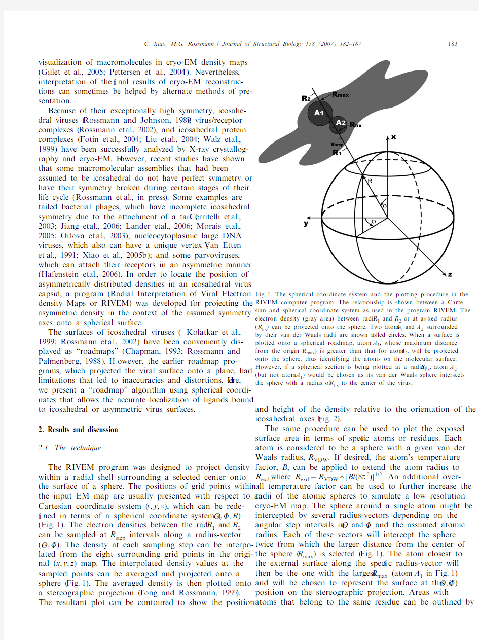
Cartesian coordinate system (x,y,z), which can be rede-W ned in terms of a spherical coordinate system ( , ,R) (Fig.1). The electron densities between the radii R1 and R2
can be sampled at R step intervals along a radius-vector
( , ). The density at each sampling step can be interpo-
lated from the eight surrounding grid points in the origi-nal (x,y,z) map. The interpolated density values at the sampled points can be averaged and projected onto a sphere (Fig.1). The averaged density is then plotted onto a stereographic projection (Tong and Rossmann, 1997). The resultant plot can be contoured to show the position and height of the density relative to the orientation of the icosahedral axes (Fig.2).
The same procedure can be used to plot the exposed surface area in terms of speci W c atoms or residues. Each atom is considered to be a sphere with a given van der Waals radius, R VDW. If desired, the atom’s temperature factor, B, can be applied to extend the atom radius to R exd,where R exd D R VDW¤[B/(8 2)]1/2. An additional over-all temperature factor can be used to further increase the radii of the atomic spheres to simulate a low resolution cryo-EM map. The sphere around a single atom might be intercepted by several radius-vectors depending on the angular step intervals in and and the assumed atomic radius. Each of these vectors will intercept the sphere twice from which the larger distance from the center of the sphere (R max) is selected (Fig.1). The atom closest to the external surface along the speci W c radius-vector will then be the one with the largest R max (atom A1 in Fig.1) and will be chosen to represent the surface at this ( , ) position on the stereographic projection. Areas with atoms that belong to the same residue can be outlined by Fig.
1. The spherical coordinate system and the plotting procedure in the RIVEM computer program. The relationship is shown between a Carte-sian and spherical coordinate system as used in the program RIVEM. The electron density (gray area) between radii R1 and R2 or at a W xed radius (R W x) can be projected onto the sphere. Two atoms A1 and A2 surrounded by their van der Waals radii are shown as W lled circles. When a surface is plotted onto a spherical roadmap, atom A1, whose maximum distance from the origin (R max) is greater than that for atom A2, will be projected onto the sphere, thus identifying the atoms on the molecular surface. However, if a spherical section is being plotted at a radius R W x, atom A2 (but not atom A1) would be chosen as its van der Waals sphere intersects the sphere with a radius of R W x to the center of the virus.
184 C. Xiao, M.G. Rossmann / Journal of Structural Biology 158 (2007) 182–187
Fig.2. Determination of the icosahedral axis positions in an asymmetric reconstruction of an icosahedral virus. (A) Self-rotation function calculated for an asymmetric reconstruction of CPV. Rotation function peaks of the W vefold ( D72°), threefold ( D120°), and twofold ( D180°) sections are shown as contours and colored red, blue, and green, respectively. The position of the symmetry axes for the mean orientation of an icosahedron is labeled with cor-responding symbols. Icosahedral asymmetric units are outlined in black. (B) Densities in the shell between 110 and 130? radii of a cryo-EM di V erence map projected onto a sphere and plotted as a stereographic projection. The map was of the di V erence between an asymmetrically reconstructed and icos-ahedrally reconstructed CPV capsid. Positive and negative densities are shown in blue and red, respectively. Contours are at intervals of one sigma above and below the mean value of the di V erence map.
Fig.3. A spherical roadmap of CPV surface residues. Basic, acid, polar, and hydrophobic residues are colored blue, red, yellow, and green, respectively. A little more than one icosahedral asymmetric unit is shown. The borders of the asymmetric unit are outlined in black, and the icosahedral symmetry axes are labeled with corresponding symbols.
C. Xiao, M.G. Rossmann / Journal of Structural Biology 158 (2007) 182–187185
a border and associated with the residue name and num-ber, resulting in a roadmap representation of the pro-jected external surface (Figs. 3 and 4). The angular intervals used to explore and can be su Y ciently small (a useful increment is about 0.1°) to allow a good repre-sentation of the actual exposed area of each residue (Figs.
3 and 4) in contrast to the W xed square unit area used by the earlier roadmap programs (Chapman, 1993; Ross-mann and Palmenberg, 1988). By superimposing the pro-jected density contours onto the roadmap of surface residues, the positional relationship between the amino acid residues and the density can be accurately interpreted (Fig.4C).
Sometimes, it is useful to plot the density on the surface of a de W ned sphere (radius R W x), as opposed to projecting a shell of density. In this case, it is more appropriate to plot only the atoms that are within their van der Waals distance of the surface with radius R W x (Fig.4B). In addi-tion, the projected density can also be of a polygonal instead of spherical shell, which is useful when the shape of the virion or its membrane is an icosahedron (B?ttcher et al., 1997a; Yan et al., 2000).
Various coloring schemes can be used to represent an assortment of features on spherical roadmaps. Speci W c residues, such as those studied by mutagenesis, can be colored to emphasize their position relative to a bound ligand. The atomic distance from the center of the virus can be used as a coloring scale to show the surface topol-ogy (Fig.4A). Other coloring schemes can be used to represent the height of projected density (Fig.2B), amino acid types (Fig.3), or electrostatic potential (Fig.4C).
Information about the orientation of symmetry elements (icosahedral operators for many viruses, W vefold symmetry for phage heads, and so forth) that can be used, for instance, to de W ne the limits of an asymmetric unit is often helpful for the interpretation of EM maps. Furthermore, it is necessary to use the symmetry information to generate all symmetry related atoms before determining surface resi-dues. Another use of the symmetry information is to impose averaging between equivalent density features.
Although the program RIVEM was initially developed for studying asymmetric features on icosahedral spherical viruses, it can also be used to investigate symmetry mis-matched features in bacteriophages and other molecular complexes. Currently, the program supports only the X-Plor map format (Brünger et al., 1998), but other map formats can be added easily. Various plotting options com-bined with appropriate symmetry operators allow RIVEM to be used for globular protein studies, such as plots of elec-trostatic potential maps (Baker et al., 2001;
Gilson and
Fig.4. Structure of CVA21 and its interaction with ICAM-1. (A) Surface residues of CVA21 are plotted onto a stereographic projection and col-ored from blue (135?) to red (165?) based on their maximum radial dis-tance from the center of the virus. (B) The location of the “pocket factor”in a 3.2? resolution electron density map of CVA21 crystals (Xiao et al., 2005a) shown as a spherical section at a W xed radius (R W x D129.6?) is out-lined in black based on the coordinates of a myristate molecule that was W tted to the density. (C) The footprint of ICAM-1 onto the CVA21 sur-face. The di V erence density between 145 and 160? radii, isolating the ICAM-1 receptor, is projected onto a stereographic diagram and con-toured in green at 1.5 sigma intervals above the mean density. The road-map is colored according to the charge potential of CVA21 calculated by the program Delphi (Gilson and Honig, 1988).
186 C. Xiao, M.G. Rossmann / Journal of Structural Biology 158 (2007) 182–187
Honig, 1988) (Fig.4C) for each of the two surfaces of a protein–protein interaction.
2.2. Application to parvoviruses
The structure of canine parvovirus (CPV) was analyzed
by means of an asymmetric cryo-EM reconstruction whose resolution had been estimated to be 30? (Hafenstein et al., 2006). The orientation of the viral capsid in the W nal asym-metric reconstruction was determined with a self-rotation
function (Tong and Rossmann, 1997) using structure factors calculated by Fourier transformation of the cryo-EM density map (Fig.2A). Although no icosahedral symmetry had been applied during the cryo-EM reconstruction, dominant, icos-
ahedrally distributed, rotation function peaks were found (Fig.2A). A di V erence map was then calculated between a cryo-EM reconstruction assuming icosahedral symmetry and an asymmetric reconstruction that had been re-oriented to
the same standard icosahedral axial system (Fig.2B). The di V erence density between 110 and 130? radii, correspond-ing to the protein shell, was plotted onto a stereographic pro-jection using RIVEM (Hafenstein et al., 2006) (Fig.2B). This
projection could be readily interpreted in terms of possible conformational changes relative to the symmetry axes, although the heights of the di V erences were too low to estab-lish the signi W cance of the results at 30? resolution. A similar
procedure had been used to investigate the icosahedral char-acter of the heavy atom distribution in the analysis of south-ern bean mosaic virus (Rayment et al., 1978).
2.3. Application to picornaviruses
The interaction between picornaviruses and their
receptors has been studied by combining X-ray crystallog-raphy and cryo-EM image analysis (Rossmann et al., 2002). Many of the cellular receptors used by picornavi-ruses belong to the immunoglobulin superfamily and bind
into a canyon-like depression on the viral surface sur-rounding each icosahedral W vefold vertex (Fig.4A). The di V erence density between the cryo-EM determined struc-ture of the virus/receptor complex and the crystallograph-
ically determined virus structure calculated at the same resolution can be accurately projected onto a roadmap of the virus surface. One example given here is the projection of the density corresponding to the intercellular adhesion
molecule-1 (ICAM-1) as seen projected onto the surface residues of the crystallographically determined coxsackie-virus A21 (CVA21) structure (Xiao et al., 2005a) (Fig.4C). Another example is a plot of the density at a W xed radius R W x to visualize the position of the “pocket factor” in CVA21 (Xiao et al., 2005a). This factor is a fatty acid-like molecule that is bound into a pocket imme-diately below the X oor of the canyon, critical to the stabil-
ity of the virion (Rossmann et al., 2002) (Fig.4B). The projected section provides an easy to interpret and accu-rate plot of the environment of the pocket factor within an icosahedral axial system.2.4. Availability of program
The program RIVEM and its source code are freely available at https://www.360docs.net/doc/556290649.html,/~viruswww/ Rossmann_home/softwares.shtml.
Acknowledgments
We thank Jianghai Zhu, Ricardo Bernal, Victor Kos-tyuchenko, Wei Zhang, and Tao Sun for helpful discussions during the development of the RIVEM program, Susan Hafenstein for providing input data, and Sharon Wilder for help in the preparation of the manuscript.
References
Acehan, D., Jiang, X., Morgan, D.G., Heuser, J.E., Wang, X., Akey, C.W., 2002. Three-dimensional structure of the apoptosome: implications for assembly, procaspase-9 binding, and activation. Mol. Cell 9, 423–432. Allen, G.S., Zavialov, A., Gursky, R., Ehrenberg, M., Frank, J., 2005. The cryo-EM structure of a translation initiation complex from Escherichia coli. Cell 121, 703–712.
Baker, N.A., Sept, D., Joseph, S., Holst, M.J., McCammon, J.A., 2001. Elec-trostatics of nanosystems: application to microtubules and the ribo-some. Proc. Natl. Acad. Sci. USA 98, 10037–10041.
Baker, T.S., Cheng, R.H., 1996. A model-based approach for determining orientations of biological macromolecules imaged by cryoelectron microscopy. J. Struct. Biol. 116, 120–130.
Baker, T.S., Olson, N.H., Fuller, S.D., 1999. Adding the third dimension to virus life cycles: three-dimensional reconstruction of icosahedral viruses from cryo-electron micrographs. Microbiol. Mol. Biol. Rev. 63, 862–922. Beck, M., F?rster, F., Ecke, M., Plitzko, J.M., Melchior, F., Gerisch, G., Bau-meister, W., Medalia, O., 2004. Nuclear pore complex structure and dynamics revealed by cryoelectron tomography. Science 306, 1387–1390. Belnap, D.M., McDermott Jr., B.M., Filman, D.J., Cheng, N., Trus, B.L., Zuccola, H.J., Racaniello, V.R., Hogle, J.M., Steven, A.C., 2000. Three-dimensional structure of poliovirus receptor bound to poliovirus. Proc.
Natl. Acad. Sci. USA 97, 73–78.
Bernal, R.A., Stock, D., 2004. Three-dimensional structure of the intact Thermus thermophilus H+-ATPase/synthase by electron microscopy.
Structure 12, 1789–1798.
B?ttcher, B., Kiselev, N.A., Stel’Mashchuk, V.Y., Perevozchikova, N.A., Borisov, A.V., Crowther, R.A., 1997a. Three-dimensional structure of infectious bursal disease virus determined by electron cryomicroscopy.
J. Virol. 71, 325–330.
B?ttcher, B., Wynne, S.A., Crowther, R.A., 1997b. Determination of the fold of the core protein of hepatitis B virus by electron cryomicros-copy. Nature (London) 386, 88–91.
Brünger, A.T., Adams, P.D., Clore, G.M., DeLano, W.L., Gros, P., Grosse-Kunstleve, R.W., Jiang, J.S., Kuszewski, J., Nilges, M., Pannu, N.S., Read, R.J., Rice, L.M., Simonson, T., Warren, G.L., 1998. Crystallogra-phy and NMR system: a new software suite for macromolecular struc-ture determination. Acta Crystallogr. Sect. D 54, 905–921.
Bubeck, D., Filman, D.J., H ogle, J.M., 2005. Cryo-electron microscopy reconstruction of a poliovirus-receptor-membrane complex. Nat.
Struct. Mol. Biol. 12, 615–618.
Cerritelli, M.E., Trus, B.L., Smith, C.S., Cheng, N., Conway, J.F., Steven, A.C., 2003. A second symmetry mismatch at the portal vertex of bacteriophage T7: 8-fold symmetry in the procapsid core. J. Mol. Biol. 327, 1–6. Chapman, M.S., 1993. Mapping the surface properties of macromolecules.
Prot. Sci. 2, 459–469.
Chen, C., Ko, Y., Delannoy, M., Ludtke, S.J., Chiu, W., Pedersen, P.L., 2004. Mitochondrial ATP synthasome. Three-dimensional structure by electron microscopy of the ATP synthase in complex formation with carriers for P i and ADP/ATP. J. Biol. Chem. 279, 31761–31768.
C. Xiao, M.G. Rossmann / Journal of Structural Biology 158 (2007) 182–187187
Cheng, Y., Zak, O., Aisen, P., Harrison, S.C., Walz, T., 2004. Structure of the human transferrin receptor-transferrin complex. Cell 116, 565–576. Chiu, W., McGough, A., Sherman, M.B., Schmid, M.F., 1999. High-resolu-tion electron cryomicroscopy of macromolecular assemblies. Trends Cell Biol. 9, 154–159.
Conway, J.F., Cheng, N., Zlotnick, A., Wing W eld, P.T., Stahl, S.J., Steven,
A.C., 1997. Visualization of a 4-helix bundle in the hepatitis B virus
capsid by cryo-electron microscopy. Nature (London) 386, 91–94. Fotin, A., Cheng, Y., Grigorie V, N., Walz, T., Harrison, S.C., Kirchhausen, T., 2004. Structure of an auxilin-bound clathrin coat and its implica-tions for the mechanism of uncoating. Nature (London) 432, 649–653. Frank, J., Radermacher, M., Penczek, P., Zhu, J., Li, Y., Ladjadj, M., Leith,
A., 1996. SPIDER and WEB: processing and visualization of images in
3D electron microscopy and related W elds. J. Struct. Biol. 116, 190–199. Gillet, A., Sanner, M., Sto Z er, D., Olson, A., 2005. Tangible interfaces for structural molecular biology. Structure 13, 483–491.
Gilson, M.K., Honig, B., 1988. Calculation of the total electrostatic energy of a macromolecular system: solvation energies, binding energies, and conformational analysis. Proteins 4, 7–18.
Grigorie V, N., 1998. Three-dimensional structure of bovine NADH:ubi-quinone oxidoreductase (complex I) at 22? in ice. J. Mol. Biol. 277, 1033–1046.
Grimes, J.M., Fuller, S.D., Stuart, D.I., 1999. Complementing crystallogra-phy: the role of cryo-electron microscopy in structural biology. Acta Crystallogr. Sect. D 55, 1742–1749.
H afenstein, S., Palermo, L.M., Kostyuchenko, V.A., Xiao, C., Morais,
M.C., Nelson, C.D.S., Bowman, V.D., Battisti, A.J., Chipman, P.R., Parrish, C.R., Rossmann, M.G., 2006. Asymmetric binding of transfer-rin receptor to parvovirus capsids, submitted for publication. Hewat, E.A., Neumann, E., Conway, J.F., Moser, R., Ronacher, B., Marlo-vits, T.C., Blaas, D., 2000. The cellular receptor of human rhinovirus 2 binds around the 5-fold axis and not in the canyon: a structural view.
EMBO J. 19, 6317–6325.
Ishikawa, T., Maurizi, M.R., Steven, A.C., 2004. The N-terminal substrate-binding domain of ClpA unfoldase is highly mobile and extends axially from the distal surface of ClpAP protease. J. Struct. Biol. 146, 180–188. Jiang, W., Chang, J., Jakana, J., Weigele, P., King, J., Chiu, W., 2006. Struc-ture of epsilon15 bacteriophage reveals genome organization and DNA packaging/injection apparatus. Nature (London) 439, 612–616. Kolatkar, P.R., Bella, J., Olson, N.H., Bator, C.M., Baker, T.S., Rossmann, M.G., 1999. Structural studies of two rhinovirus serotypes complexed with fragments of their cellular receptor. EMBO J. 18, 6249–6259. Lander, G.C., Tang, L., Casjens, S.R., Gilcrease, E.B., Prevelige, P., Poliakov, A., Potter, C.S., Carragher, B., Johnson, J.E., 2006. The struc-ture of an infectious P22 virion shows the signal for headful DNA packaging. Science 312, 1791–1795.
Leiman, P.G., Chipman, P.R., Kostyuchenko, V.A., Mesyanzhinov, V.V., Rossmann, M.G., 2004. Three-dimensional rearrangement of proteins in the tail of bacteriophage T4 on infection of its host. Cell 118, 419–429. Liu, Z., Yan, H., Wang, K., Kuang, T., Zhang, J., Gui, L., An, X., Chang, W., 2004. Crystal structure of spinach major light-harvesting complex at 2.72? resolution. Nature (London) 428, 287–292.
Ludtke, S.J., Baldwin, P.R., Chiu, W., 1999. EMAN: semiautomated software for high-resolution single-particle reconstructions. J. Struct. Biol. 128, 82–97. Ludtke, S.J., Chen, D.H., Song, J.L., Chuang, D.T., Chiu, W., 2004. Seeing GroEL at 6? resolution by single particle electron cryomicroscopy.
Structure 12, 1129–1136.
Matadeen, R., Patwardhan, A., Gowen, B., Orlova, E.V., Pape, T., Cu V, M., Mueller, F., Brimacombe, R., van Heel, M., 1999. The Escherichia coli large ribosomal subunit at 7.5? resolution. Structure 7, 1575–1583. Morais, M.C., Choi, K.H., Koti, J.S., Chipman, P.R., Anderson, D.L., Rossmann, M.G., 2005. Conservation of the capsid structure in tailed dsDNA bacteriophages: the pseudoatomic structure of 29. Mol. Cell 18, 149–159.Orlova, E.V., Gowen, B., Dr?ge, A., Stiege, A., Weise, F., Lurz, R., van Heel, M., Tavares, P., 2003. Structure of a viral DNA gatekeeper at 10? reso-lution by cryo-electron microscopy. EMBO J. 22, 1255–1262. Pettersen, E.F., Goddard, T.D., Huang, C.C., Couch, G.S., Greenblatt, D.M., Meng, E.C., Ferrin, T.E., 2004. UCSF Chimera—a visualization system for exploratory research and analysis. J. Computat. Chem. 25, 1605–1612. Rayment, I., Johnson, J.E., Suck, D., Akimoto, T., Rossmann, M.G., 1978.
An 11? resolution electron density map of southern bean mosaic virus.
Acta Crystallogr. Sect. B 34, 567–578.
Roseman, A.M., 2000. Docking structures of domains into maps from cryo-electron microscopy using local correlation. Acta Crystallogr.
Sect. D 56, 1332–1340.
Rossmann, M.G., Arisaka, F., Battisti, A.J., Bowman, V.D., Chipman, P.R., Fokine, A., H afenstein, S., Kanamaru, S., Kostyuchenko, V.A., Mesyanzhinov, V.V., Shneider, M.M., Morais, M.C., Leiman, P.G., Palermo, L.M., Parrish, C.R., Xiao, C., in press. From structure of the complex to understanding of the biology. Acta Crystallogr. Sect. D. Rossmann, M.G., Bernal, R., Pletnev, S.V., 2001. Combining electron microscopic with X-ray crystallographic structures. J. Struct. Biol. 136, 190–200.
Rossmann, M.G., He, Y., Kuhn, R.J., 2002. Picornavirus-receptor interac-tions. Trends Microbiol. 10, 324–331.
Rossmann, M.G., Johnson, J.E., 1989. Icosahedral RNA virus structure.
Annu. Rev. Biochem. 58, 533–573.
Rossmann, M.G., Morais, M.C., Leiman, P.G., Zhang, W., 2005. Combin-ing X-ray crystallography and electron microscopy. Structure 13, 355–362.
Rossmann, M.G., Palmenberg, A.C., 1988. Conservation of the putative receptor attachment site in picornaviruses. Virology 164, 373–382. Serysheva, I.I., Hamilton, S.L., Chiu, W., Ludtke, S.J., 2005. Structure of Ca2+ release channel at 14? resolution. J. Mol. Biol. 345, 427–431. Tong, L., Rossmann, M.G., 1997. Rotation function calculations with GLRF program. Meth. Enzymol. 276, 594–611.
Van Etten, J.L., Lane, L.C., Meints, R.H., 1991. Viruses and viruslike parti-cles of eukaryotic algae. Microbiol. Rev. 55, 586–620.
van Heel, M., Gowen, B., Matadeen, R., Orlova, E.V., Finn, R., Pape, T., Cohen, D., Stark, H., Schmidt, R., Schatz, M., Patwardhan, A., 2000.
Single-particle electron cryo-microscopy: towards atomic resolution.
Quart. Rev. Biophys. 33, 307–369.
Volkmann, N., H anein, D., 2003. Docking of atomic models into recon-structions from electron microscopy. Meth. Enzymol. 374, 204–225. Walz, J., Koster, A.J., Tamura, T., Baumeister, W., 1999. Capsids of tricorn protease studied by electron cryomicroscopy. J. Struct. Biol. 128, 65–68. Wriggers, W., Milligan, R.A., McCammon, J.A., 1999. Situs: a package for docking crystal structures into low-resolution maps from electron microscopy. J. Struct. Biol. 125, 185–189.
Xiao, C., Bator-Kelly, C.M., Rieder, E., Chipman, P.R., Craig, A., Kuhn, R.J., Wimmer, E., Rossmann, M.G., 2005a. The crystal structure of coxsackie-virus A21 and its interaction with ICAM-1. Structure 13, 1019–1033. Xiao, C., Chipman, P.R., Battisti, A.J., Bowman, V.D., Renesto, P., Raoult,
D., Rossmann, M.G., 2005b. Cryo-electron microscopy of the giant
Mimivirus. J. Mol. Biol. 353, 493–496.
Yan, X., Olson, N.H., Van Etten, J.L., Bergoin, M., Rossmann, M.G., Baker, T.S., 2000. Structure and assembly of large lipid-containing dsDNA viruses. Nat. Struct. Biol. 7, 101–103.
Yonekura, K., Maki-Yonekura, S., Namba, K., 2005. Building the atomic model for the bacterial X agellar W lament by electron cryomicroscopy and image analysis. Structure 13, 407–412.
Zhou, Z.H., Dougherty, M., Jakana, J., He, J., Rixon, F.J., Chiu, W., 2000.
Seeing the herpesvirus capsid at 8.5?. Science 288, 877–880.
Zhou, Z.H., McCarthy, D.B., O’Connor, C.M., Reed, L.J., Stoops, J.K., 2001. The remarkable structural and functional organization of the eukaryotic pyruvate dehydrogenase complexes. Proc. Natl. Acad. Sci.
USA 98, 14802–14807.
09电信电子线路课程设计题目
电子线路课程设计题目 (模电、数电部分) 一、锯齿波发生器 二、语音放大电路 三、可编程放大器 四、数字频率计 五、可调电源 六、汽车尾灯控制电路 2011.09
一、设计一高线性度的锯齿波发生器 要求: (1)利用555定时器和结型场效应管构成的恒流源设计一高线性度的锯齿波发生器;参考电路如图所示; (2)在EWB中对该电路进行仿真; (3)焊接电路并进行调试;调试过程中思考: a、电路中两个三极管的作用是什么?其工作状态是怎么样的? b、R3阻值的大小会对锯齿波的线性度产生什么影响? c、输出锯齿波的幅值范围多大? d、调节电路中的可调电阻对波形有什么影响? e、LM324的作用是什么? (4)参考电路图中采用的是结型场效应管设计的,若采用N沟道增强型VMOS管和555定时器来设计一高线性度的锯齿波发生器,该如何设计? LM324 图2 高线性度锯齿波发生器的设计
二、语音放大电路的设计 通常语音信号非常微弱,需要经过放大、滤波、功率放大后驱动扬声器。 要求: (1)采用集成运算放大器LM324和集成功放LM386N-4设计一个语音放大电路;假设语音信号的为一正弦波信号,峰峰值为5mV,频率范围为100Hz~1KHz,电路总体原理图如下所示; 图4 语音放大电路 (2)仔细分析以上电路,弄清电路构成,指出前置放大器的增益为多少dB?通带滤波器的增益为多少dB? (3)参照以上电路,焊接电路并进行调试。 a、将输入信号的峰峰值固定在5mV,分别在频率为100Hz和1KHz的条件下测试前 置放大的输出和通带滤波器的输出电压值,计算其增益,将计算结果同上面分析 的理论值进行比较。 b、能过改变10K殴的可调电阻,得到不同的输出,在波形不失真的条件下,测试集 成功放LM386在如图接法时的增益; c、将与LM386的工作电源引脚即6引脚相连的10uF电容断开,观察对波形的影响, 其作用是什么? d、扬声器前面1000uF电容的作用是什么?
安全电子邮件系统的设计跟实现
安全电子邮件系统的设计与实现 摘要随着电子邮件越来越广泛的应用,电子邮件的安全性问题也越显突出,文章提出了一种提供数据加密和数字签名的安全电子邮件系统,并详细讨论了其设计与实现技术。 关键词电子邮件,MOSS,数字签名,数据加密 1 前言 近年来,伴随Internet的迅猛发展,电子邮件以其使用方便、快捷等特点已经成为Internet上最普及的应用。但是,由于电子邮件在Internet上未加任何保密措施的情况下,均以不加密的可读文件被传输,这样就存在邮件被人偷窥、篡改、截获、以及身份被人伪造等若干不安全因素,由此限制了电子邮件在重要信息传递与交换领域的应用。 目前国外已经出现了很多安全电子邮件软件,但是,由于他们对安全产品出口的限制以及国外软件可能存在“安全后门”,研制和开发具有自主知识产权的安全电子邮件软件,具有重大的政治意义和经济价值。 本文介绍的基于Windows平台上用Visual c++6.0开发的安全电子邮件系统,提供了电子邮件的保密性、完整性、不可否认性及身份认证。 2 设计与实现 本文实现的功能:收发邮件、转发邮件、答复邮件等标准邮件客户端功能;为防止邮件被窃听,自动加密邮件;防止邮件被篡改及伪冒、发送方抵赖,自动执行数字签名;为保证私钥高度安全,支持本地产生RSA密钥;地址簿除方便易用,还具有许多特殊的如公钥环管理等功能;支持从文件中导入及自动从邮件中获取公钥或数字证书;支持BIG5与GB2312的内码转换以及UUEncode编码方式;支持多帐户以及口令保护;支持拨号上网以及打印功能。 2.1 总体设计 系统有多个功能模块构成,总体结构如图1所示。 (1)个人密钥管理 个人密钥管理模块完成产生RSA密钥对、安全 地保存私钥、发布公钥、作废公钥的功能。 根据用户提供的信息(密钥长度、随机数种子、保护口令以及含用户名的基本信息),采用RSA算法生成模块产生公钥、私钥对。 图1 安全电子邮件系统结构图 采用MD5和IDEA加密算法对RSA私钥、用户口令以及随机数种子进行加密,实现安全保存。 本系统提供两种方式实现公钥的发布。一是基于信任模式下的方式:将公钥发送到文件或者通过E-mail发送;另一种是基于层次结构证书认证机构的认证方式:申请数字证书。 作废密钥也提供两种方式:本地删除和申请作废证书。后一种适用于公钥发布选择第二种方式的用户。 (2)发送邮件 发送邮件模块完成撰写邮件、格式化邮件、SMTP协议的实现功能。 撰写邮件由邮件编辑器完成。 格式化邮件严格按MIME协议来进行,对普通邮件直接发送,而对安全邮件按照MOSS协议对邮
模拟电路课程设计心得体会
模拟电路课程设计心得 体会 内部编号:(YUUT-TBBY-MMUT-URRUY-UOOY-DBUYI-0128)
精选范文:《模拟电路》课程设计心得体会(共2篇)本学期我们开设了《模拟电路》与《数字电路》课,这两门学科都属于电子电路范畴,与我们的专业也都有联系,且都是理论方面的指示。正所谓“纸上谈兵终觉浅,觉知此事要躬行。”学习任何知识,仅从理论上去求知,而不去实践、探索是不够的,所以在本学期暨模电、数电刚学完之际,紧接着来一次电子电路课程设计是很及时、很必要的。这样不仅能加深我们对电子电路的任职,而且还及时、真正的做到了学以致用。这两周的课程设计,先不说其他,就天气而言,确实很艰苦。受副热带高气压影响,江南大部这两周都被高温笼罩着。人在高温下的反应是很迟钝的,简言之,就是很难静坐下来动脑子做事。天气本身炎热,加之机房里又没有电扇、空调,故在上机仿真时,真是艰熬,坐下来才一会会,就全身湿透,但是炎炎烈日挡不住我们求知、探索的欲望。通过我们不懈的努力与切实追求,终于做完了课程设计。在这次课程设计过程中,我也遇到了很多问题。比如在三角波、方波转换成正弦波时,我就弄了很长时间,先是远离不清晰,这直接导致了我无法很顺利地连接电路,然后翻阅了大量书籍,查资料,终于在书中查到了有关章节,并参考,并设计出了三角波、方波转换成正弦波的电路图。但在设计数字频率计时就不是那么一帆风顺了。我同样是查阅资料,虽找到了原理框图,但电路图却始终设计不出来,最后实在没办法,只能用数字是中来代替。在此,我深表遗憾!这次课程设计让我学到了很多,不仅是巩固了先前学的模电、数电的理论知识,而且也培养了我的动手能力,更令我的创造性思维得到拓展。希望今后类似这样课程设计、类似这样的锻炼机会能更多些!
安全阀分类和参数选型方法详解(精)
安全阀的介绍与选用 一概述 安全阀是锅炉、压力容器和其他受压力设备上重要的安全附件。其动作可靠性和性能好坏直接关系到设备和人身的安全,并与节能和环境保护紧密相关。而有的用户和设计部门在选型时,总是选错型号。为此本文对安全阀的选用加以分析。 二、定义 所谓安全阀广义上讲包括泄放阀,从管理规则上看,直接安装在蒸汽锅炉或一类压力容器上,其必要条件是必须得到技术监督部门认可的阀门,狭义上称之为安全阀,其他一般称之为泄放阀。安全阀与泄放阀在结构和性能上很相似,二者都是在超过开启压力时自动排放内部的介质,以保证生产装置的安全。由干存在这种本质上类似性,人们在使用时,往往将二者混同,另外,有些生产装置在规则上也规定选用哪种均可。因此,二者的不同之处往往被忽视。从而也就出现了许多间题。如果要将二者作出比较明确的定义,则可按照《ASME 锅炉及压力容器规范》第一篇中所阐述的定义来理解: (l)安全阀(Safety Valve)一种由阀前介质静压力驱动的自动泄压装置。其特征为具有突开的全开启动作。用于气体或蒸汽的场合,如图1。
(2)泄放阀(Relief Valve),又称溢流阀一种由阀前介质静压力驱动的自动泄压装置。它随压力超过开启力的增长而按比例开启。主要用于流体的场合。如图2所示。 (3)安全泄放阀(Safet Relief Valve),又称安全溢流阀一种由介质压力驱动的自动泄压装置。根据使用场合不同既适用作安全阀也适用作泄放阀。以日本为例,给安全阀和泄放阀作出明确定义的比较少,一般用作锅炉这类大型贮能压力容器的安全装置称之为安全
阀,安装在管道上或其他设设施上的称之为泄放阀。不过,若按日本通产省的《火力发电技术标准》的规定看,设备上安全保障的重要部分,指定使用安全阀,如锅炉、过热器、再热器等。而在减压阀的下侧需要与锅炉和涡轮机相接的场合,都需要安装泄放阀或安全阀。如此看,安全阀要求比泄放阀更具可靠性。另外,从日本劳动省的高压气体管理规则、运输省及各级船舶协会的规则中,对安全排放量的认定和规定来看,我们把保证了排放量的称之为安全阀,而不保证排放量的阀门称作泄放阀。在国内不论全启式或微启式统称为安全阀。 三、选型 1.分类 目前大量生产的安全阀有弹簧式和杆式两大类。另外还有冲量式安全阀、先导式安全阀、安全切换阀、安全解压阀、静重式安全阀等。弹簧式安全阀主要依靠弹簧的作用力而工作,弹簧式安全阀中又有封闭和不封闭的,一般易燃、易爆或有毒的介质应选用封闭式,蒸汽或惰性气体等可以选用不封闭式,在弹簧式安全阀中还有带扳手和不带扳手的。扳手的作用主要是检查阀瓣的灵活程度,有时也可以用作手动紧急泄压用,如图3。杠杆式安全阀主要依靠杠杆重锤的作用力而工作,但由于杠杆式安全阀体积庞大往往限制了选用范围。温度较高时选用带散热器的安全阀。
南京理工大学电子线路课程设计(优秀)
南京理工大学 电子线路课程设计 实验报告
摘要 本次实验利用QuartusII7.0软件并采用DDS技术、FPGA芯片和D/A转换器,设计了一个直接数字频率信号合成器,具有频率控制、相位控制、测频、显示多种波形等功能。 并利用QuartusII7.0软件对电路进行了详细的仿真,同时通过SMART SOPC实验箱和示波器对电路的实验结果进行验证。 报告分析了整个电路的工作原理,还分别说明了设计各子模块的方案和编辑、以及仿真的过程。并且介绍了如何将各子模块联系起来,合并为总电路。最后对实验过程中产生的问题提出自己的解决方法。并叙述了本次实验的实验感受与收获。 关键词数字频率信号合成器频率控制相位控制测频示波器 Abstract This experient introduces using QuartusII7.0software, DDS technology,FPGA chip and D/A converter to design a multi—output waveform signal generator in which the frequency and phase are controllable and test frequency,display waveform. It also make the use of software QuartusII7.0 a detailed circuit simulation, and verify the circuit experimental results through SMART SOPC experiment box and the oscilloscope. The report analyzes the electric circuit principle of work,and also illustrates the design of each module and editing, simulation, and the process of using the waveform to testing each Sub module. Meanwhile,it describes how the modules together, combined for a total circuit. Finally the experimental problems arising in the process of present their solutions. And describes the experience and result of this experiment. Keywords multi—output waveform signal- generator frequency controllable phase controllable test frequency oscilloscope 目录
电子邮件安全
电子邮件安全(一) 【教学目的要求】熟悉各名词、术语的含义,掌握基本概念,特别是PGP、PGP 操作描述。掌握网络安全体系结构、安全攻击方法等基本概念。 【重点】PGP、PGP操作描述 【难点】PGP、PGP操作描述 【教学方法】多媒体教学和传统教学相结合。 【课时安排】2课时 【教学过程】 【导入】E-mail 是Internet上最大的应用之一,安全电子邮件主要解决身份认证和保密性相关的安全问题。 【讲解】 安全电子邮件 涉及到的问题: 安全算法的选择 系统邮件的信息格式 如何实现认证和信任管理 邮件服务器的可靠性 应用实际例子:PGP、S/MIME等 邮件信息格式 早期只支持ASCII文本格式 随着Email的发展需要发送各种类型数据,形成了MIME (Multipurpose Internet Mail Extensions,多用途网际邮件扩展) 5.1 PGP(Pretty Good Privacy) 1.提供了一种机密性和数字签名的安全服务,广泛用于电子邮件和文件存储的安全应 用 2.选择各种经过实际验证的安全算法作为基础构件 3.将这些算法有机整合起来,形成一个通用的独立于操作系统和硬件平台的应用程序 4.是一个自由软件包(https://www.360docs.net/doc/556290649.html,) PGP的优势 1.免费得到, 支持多种平台(DOS/Windows、Unix、Macintosh等) 2.建立在一些经过实际验证的算法基础上(RSA、DSS、Diffie-Hellman、IDEA、3DES、 SHA-1、MD5),选用算法的生命力和安全性得到公众认可 3.应用范围极其广泛 4.不从属于任何政府机构和标准化组织 5.已经成为互联网标准文档(RFC3156) 6.免费得到, 支持多种平台(DOS/Windows、Unix、Macintosh等) 7.建立在一些经过实际验证的算法基础上(RSA、DSS、Diffie-Hellman、IDEA、3DES、
电子线路CAD课程设计汇本报告
目录 第一章绪论 (2) 1.1设计目的及要求 (2) 1.2 设计流程 (2) 第二章原理分析 (3) 2.1 最小系统的结构 (3) 2.2 各电路的原理分析 (3) 第三章原理图绘制 (8) 3.1 原理图设计的一般步骤 (8) 3.2 元件库的设计 (8) 第四章PCB图的绘制 (12) 4.1 创建该项目下的PCB文件 (12) 4.2 绘制PCB (12) 总结 (15) 参考文献 (16) 附录 (17)
第一章绪论 1.1 设计目的及要求 电子线路CAD是以电为主的机电一体化工科专业的专业基础课,作为通信工程专业,要通过学习一种典型电子线路CAD软件altium designer,掌握计算机绘制包括电路(原理)图、印刷电路板图在的电气图制图技能和相应的计算机仿真技能。通过本次设计,达到了解DXP软件的运用,认识51单片机的最小系统的构成以及学会改正制图过程中遇到的问题。 根据课程设计的题目,独立设计、绘制和仿真电路,实现51单片机的最最小系统。要求如下: (1)设计出原理图自己绘制51单片机最小系统的电路图,分析电路图中各小电路的工作原理; (2)用DXP软件画出原理图; (3)用DXP软件仿真出PCB板,熟悉电路板的加工工艺; 1.2 设计流程 本次设计主要是熟练运用DXP作出最小单片机系统的电路图,以下通过介绍最小系统的各部分电路的电路图及原理,通过在DXP上绘制原理图,检查并
修改错误,最后生成完整PCB板。
第二章原理分析 2.1 最小系统的结构 单片机单片微控制器,是在一块芯片中集成了CPU(中央处理器)、RAM (数据存储器)、ROM(程序存储器)、定时器/计数器和多种功能的I/O(输入和输出)接口等一台计算机所需要的基本功能部件,从而可以完成复杂的运算、逻辑控制、通信等功能。 单片机最小系统电路主要集合了串口电路、USB接口电路、蜂鸣器与继电器电路、AD&DA转换电路、数码管电路、复位电路、晶振电路和4*4矩阵键盘等电路。如下介绍几种简单的电路设计。 下图是本次设计的的几个有关电路图总体框图:
安全阀计算与选型
安全阀计算与选型 1. 确定确定安全阀类型安全阀类型 根据卸放介质物性、卸放量确定安全阀类型。 2. 确定安全阀公称压力 根据介质操作条件确定PN,选定弹簧工作压力级。 3. 安全阀安全阀计算计算 3.1 由工艺计算软件(hysis,pro II,aspen)计算获得介质基本物性数据(比重ρ,分子量M, 粘度μ,泄放量Gv,气体特性系数C,流量系数Kf,压缩系数Z,最高泄放压力Pm,泄放温度Ti,操作压力P 0,整定压力Ps)。 3.2 计算公式: 安全阀的计算参照GB/T 12241-2005(它与ISO 4126 安全阀一般要求计算方法相同) 中 的公式并依据实测额定排量系数来计算安全阀的额定排量,进而确定安全阀的口径,是比较可靠的计算方法。具体计算公式见GB/T 12241-2005 6.3节/6.5节。 3.2.1 介质为气体或蒸汽 1)临界流动下的理论排量计算 在下列条件下达到临界流动: 临界流动下的理论排量计算公式: 2)亚临界流动下的理论排量计算: 在下列条件下达到亚临界流动: 亚临界流动下的理论排量计算公式: 3)Excel 表格计算安全阀卸放面积A 0(作者Huang WenJia)
3.3 将必须的介质物性数据编入Excel 表格,并在安全阀卸放面积栏编好计算公式(见安全阀 计算excel 表格)。 安全阀安全阀的选用与的选用与的选用与计算实例计算实例计算实例 安全阀系压力容器在运行中实现超压泄放的安全附件之一,也是在线压力容器定期检验中必检 项目。它包括防超压和防真空两大系列,即一为排泄容器内部超压介质防止容器失效,另一方面则为吸入外部介质以防止容器刚度失效。凡符合《容规》适用范围的压力容器按设计图样的要求装设安全阀。 一.安全阀的选用安全阀的选用 1. 1. 安全阀安全阀安全阀各种参数的确定各种参数的确定各种参数的确定 a)确定安全阀公称压力。 根据阀门材料、工作温度和最大工作压力选定公称压力。 b) 确定安全阀的工作压力等级。 根据压力容器的设计压力和设计温度选定工作压力等级。安全阀的工作压力与弹簧的工作压力级有着不同的含义,不能混为一谈。工作压力是指安全阀正常运行时阀前所承受的静压力,它与被保护系统或设备的工作压力相同。而弹簧的工作压力级则是指某一根弹簧所允许使用的工作压力范围,在该压力范围内,安全阀的开启压力(即整定压力)可以通过改变弹簧的预紧压缩量进行调节。同一公称压力的安全阀,根据弹簧设计要求,可以分为多种不同的工作压力级。具体划分见下表,划分的前提是能足以保证各个工作压力级的压力上限与下限均能符合有关标准所规定的动作性能指标。 选用安全阀时,应根据所需开启压力值确定阀门的工作压力级。 表1 安全阀公称压力PN 与弹簧工作压力关系表 PN 弹簧工作压力等级 1.6 0.06~0.1 >0.12 >0.16~0.25 >0.25~0.4 >0.4~0.5 >0.5~0.6 >0.6~0.8 >0.8~1.0 >1.0~1.3 >1.3~1.6 2.5 >1.3~1.6 >1.6~2.0 >2.0~2.5 只能用于大于 1.3MP 6.4 ->1.3~1.6 >1.6~2.0 >2.0~2.5 >2.5~3.2 >3.2~4.0 >4.0~6.4 只能用于大于1.3MPa 10 >4~5 >5~6.4 >6.4~8 >8~10 只能用于大于4.0MPa
安全阀的正确使用、选型和定压(2021)
When the lives of employees or national property are endangered, production activities are stopped to rectify and eliminate dangerous factors. (安全管理) 单位:___________________ 姓名:___________________ 日期:___________________ 安全阀的正确使用、选型和定压 (2021)
安全阀的正确使用、选型和定压(2021)导语:生产有了安全保障,才能持续、稳定发展。生产活动中事故层出不穷,生产势必陷于混乱、甚至瘫痪状态。当生产与安全发生矛盾、危及职工生命或国家财产时,生产活动停下来整治、消除危险因素以后,生产形势会变得更好。"安全第一" 的提法,决非把安全摆到生产之上;忽视安全自然是一种错误。 安全阀是锅炉压力容器以及所有承压设备的重要安全附件之一,它是一种自动阀门,当承压设备超过允许的工作压力后,安全阀自动开启,排放出多余的介质。当压力降到允许的工作压力后,安全阀自动关闭,设备正常运行。由此可见安全阀在承压设备安全运行中起着很重要的作用。 笔者在从事安全阀校验工作中发现有不少用户如何对安全阀的正确使用、选型和定压上缺少认识,甚至什么叫安全阀都不懂。在此笔者经过十几年的工作经验谈谈自己的看法。 一、安全阀的选型 1、小型汽水两用锅炉不得采用弹簧式安全阀 根据“小型和常压热水锅炉安全监察规程”规定应当采用水封式安全装置,而且水封管的直径不得小于25mm,其有效水柱高度不得超过4m且只允许负偏差,也可选用静重式安全阀。 2、蒸汽锅炉应选用弹簧全启式安全阀
电子线路课程设计am调幅发射机设计报告
电子线路课程设计 总结报告 学生姓名: 可行性,选择适合设计方案,并对设计方案进行必要的论证。本课题以小功率调幅发射机为设计对象,并对其主振级、低频电压放大级、调制级、高频功率放大级进行了详细的设计、论证、调试及仿真,并进行了整机的调试与仿真。设计具体包括以下几个步骤:一般性理论设计、具体电路的选择、根据指标选定合适器件并计算详细的器件参数、用multisim进行设计的仿真、根据仿真结果检验设计指标并进行调整。最后对整个设计出现的问题,和心得体会进行总结。 关键词调幅发射机;振荡器;multisim仿真设计
一、设计内容及要求 (一)设计内容:小功率调幅AM发射机设计 1.确定小功率调幅发射机的设计方案,根据设计指标对既定方案进行理论设计分析, 并给出各单元电路的理论设计方法和实用电路设计细节,其中包括元器件的具体选择、参数调整。 根据设计要求,要求工作频率为10MHz,输出功率为1W,单音调幅系数 m。由于载波频率为10Mhz,大多数振荡器皆可满足,提供了较多的选择且不需要 8.0 = a 倍频。由于输出功率小,因此总体电路具有结构简单,体积较小的特点。其总体电路结构 可分为主振荡电路(载波振荡电路)、缓冲隔离电路、音频放大电路、振幅调制电路、功
(二)单元电路方案论证 1.主振荡电路 主振荡电路是调幅发射机的核心部件,载波的频率稳定度和波形的稳定度直接影响到发射信号的质量,因此,主振荡电路产生的载波信号必须有较高的频率稳定度和较小的波形失真度,主振荡电路可以有四种设计方案:RC正弦波振荡电路、石英晶体振荡电路、三点振荡电路、改进三点式(克拉泼)振荡电路。 2.振幅调制电路 振幅调制电路是小信号调幅发射机的核心组成部分,该单元实现将音频信号加载到载波上以调幅波形式发送出去,振幅调制电路要能保证输出的信号为载波信号的振幅随调制信号线性变化。
电子线路课程设计报告
石英晶体好坏检测电路设计 设计要求 1. 利用高频电子线路及其先修课程模拟电路的知识设计一个电子线路2.利用该电子线路的要求是要求能够检测石英晶体的好坏 3. 要求设计的该电子线路能够进行仿真 4. 从仿真的结果能够直接判断出该石英晶体的好坏 5. 能够理解该电子线路检测的原理 6. 能够了解该电子线路的应用 成果简介设计的该电子线路能够检测不同频率石英晶体的好坏。当有该石英晶体(又称晶振)的时候,在输出端接上一个示波器能够有正弦波形输出,而当没有 该晶振的时候,输出的是直流,波形是一条直线。所以利用该电路可以在使 用晶振之前对其进行检测。 报告正文 (1)引言: 在高频电子线路中,石英晶体谐振器(也称石英振子)是一个重要的高频部件,它广泛应用于频率稳定性高的振荡器中,也用作高性能的窄带滤波 器和鉴频器。其中石英晶体振荡器就是利用石英晶体谐振器作滤波元件构成 的振荡器,其振荡频率由石英晶体谐振器决定。与LC谐振回路相比,石英晶 体谐振器有很高的标准性,采用品质因数,因此石英晶体振荡器具有较高的 频率稳定度,采用高精度和稳频措施后,石英晶体振荡器可以达到很高的频 率稳定度。正是因为石英晶体谐振器的这一广泛的应用和重要性,所以在选 择石英晶体谐振器的时候,应该选择质量好的。在选择的时候要对该晶振检 测才能够知道它的好坏,所以要设计一个检测石英晶体好坏的电路。 (2)设计内容: 设计该电路的原理如下:
如下图所示,BX为待测石英晶体(又名晶振),插入插座X1、X2,按下按钮SB,如果BX是好的,则由三极管VT1、电容器C1、C2等构成的振荡器工作,振荡信号从VT1发射极输出,经C3耦合到VD2进行检波、C4滤波,变成直流信号电压,送至VT2基极,使VT2导通,发光二极管H发光,指示被测石英晶体是好的。若H不亮,则表明石英晶体是坏的。适当改变C1、C2的容值,即可用于测试不同频率的石英晶体。 图一石英晶体好坏检测电路检测原理图 在上面的电路中,晶振等效于电感的功能,与C1和C2构成电容三点式振荡电路,振荡频率主要由C1、C2和C3以及晶振构成的回路决定。即由晶振电 抗X e 与外部电容相等的条件决定,设外部电容为C L ,则=0,其中C l 是C1、 C2和C3的串联值。 (3)电路调试过程: 首先是电路的仿真过程,该电路的仿真是在EWB软件下进行的,下面是将原图画到该软件后的截图:
电子邮件安全
电子邮件安全 电子邮件通常称为E-mail,是计算机网络上最早也是最重要的应用之一,世界各地的人们通过电子邮件互相传递信息,进行网上交流。电子邮件已经成为现在人们互相往来的一种常用方式。电子邮件是一种将电话通信的快速与邮政通信的直观易懂想结合的通信手段,与电话通信以及邮政通信相比,电子邮件有它得天独厚的优点。但是,在电子邮件飞速发展的同时,电子邮件的安全问题也随之浮出水面。 一.电子邮件的安全隐患 针对电子邮件的攻击分为两种,一种世界对电子邮件的攻击,如窃取电子邮件密码,截获发送邮件内容,发送邮件炸弹;另一种是间接对电子邮件的攻击,如通过邮件传输病毒木马。产生电子邮件安全隐患主要有3个方面: (1)电子邮件传送协议自身的先天安全隐患。众所周知,电子邮件传输采用的是SMTP 协议,即简单邮件传输协议,它传输的数据没有经过任何加密,只要攻击者在其传输途中把它截获即可知道内容。 (2)由邮件接收端软件的设计缺陷导致的安全隐患。如微软的OutLook曾存在的安全隐患可以是攻击者编制一定代码让木马或者病毒自动运行。 (3)用户个人的原因到时的安全隐患。 二.电子邮件的安全技术 1.端到端的安全电子邮件技术 端到端的安全电子邮件技术保证邮件从发出到被接收的整个过程中,内容无法被修改,并且不可否认。PGP和S/MIME是目前两种成熟的端到端安全电子邮件标准。 PGP(Pretty Good Privacy)被广泛采用,通过单向散列算法对邮件内容进行签名,以保证信件内容无法被修改,使用公钥和私钥技术保证邮件内容保密且不可否认。发信人与收信人的公钥都保存在公开的地方,公钥的权威性则可由第三方进行签名认证。在PGP系统中,信任是双方的直接关系。 S/MIME(Secure/Multipurpose Internet Mail Extensions)与PGP一样,利用单向散列算法、公钥与私钥的加密体系。但是,S/MIME也有两方面与PGP不同:议事S/MIME的认证机制依赖于层次结构的证书认证机构,所有下一级的组织和个人的证书由上一级的组织负责认证,而嘴上一级的组织(根证书)之间相互认证;二是S/MIME将信件内容加密签名后作为特殊的附件传送。 2.传输层的安全电子邮件技术 电子邮件包括信头和信体。端到端安全电子邮件技术一般只对信体进行加密和签名,信头则由于邮件传输中寻址和路由的需要,必须保证不变。目前,主要有两种方式能够实现电子邮件在传输中的安全:一种是利用SSL SMTP和SSL POP,另一种是利用VPN或者其他IP通道技术。 3.电子邮件加密 加密时一种限制对网络上传输数据的访问权的技术,加密的基本功能包括: (1)防止不速之客查看机密的数据文件。 (2)防止机密数据被泄露或篡改。 (3)防止特权用户(如系统管理员)查看私人数据文件。 (4)使入侵者不能轻易地查找一个数据文件
《低频电子线路》课程设计 )
辽宁师范大学《低频电子线路》课程设计 (2009级本科) 题目:红外控制9 学院:物理与电子技术学院 专业:电子信息工程 班级: 班级学号: 姓名: 指导教师: 完成日期:2011 年 6月23日 模拟电子技术课程设计:红外控制九 一内容摘要 红外控制9——红外遥控发射接收系统。该系统主要通过三极管NPN、集成块CD4011以及若干元器件组成红外发射装置产生38—40KHZ频率的信号,由光电二极管接收并通过NE555振荡电路,经过电解电容和二极管作用使小灯发光以达到设计目的。 二关键词 一般PCB基本设计流程如下:前期准备->PCB结构设计->PCB布局->布线->布线优化和丝印->网络和DRC检查和结构检查->制版。 第一:前期准备。这包括准备元件库和原理图。“工欲善其事,必先利其器”,
要做出一块好的板子,除了要设计好原理之外,还要画得好。在进行PCB设计之前,首先要准备好原理图SCH的元件库和PCB的元件库。元件库可以用peotel自带的库,但一般情况下很难找到合适的,最好是自己根据所选器件的标准尺寸资料自己做元件库。原则上先做PCB的元件库,再做SCH的元件库。PCB的元件库要求较高,它直接影响板子的安装;SCH的元件库要求相对比较松,只要注意定义好管脚属性和与PCB元件的对应关系就行。PS:注意标准库中的隐藏管脚。之后就是原理图的设计,做好后就准备开始做PCB设计了。 第二:PCB结构设计。这一步根据已经确定的电路板尺寸和各项机械定位,在PCB设计环境下绘制PCB板面,并按定位要求放置所需的接插件、按键/开关、螺丝孔、装配孔等等。并充分考虑和确定布线区域和非布线区域(如螺丝孔周围多大范围属于非布线区域)。 第三:PCB布局。布局说白了就是在板子上放器件。这时如果前面讲到的准备工作都做好的话,就可以在原理图上生成网络表(Design->CreateNetlist),之后在PCB图上导入网络表(Design->LoadNets)。就看见器件哗啦啦的全堆上去了,各管脚之间还有飞线提示连接。然后就可以对器件布局了。一般布局按如下原则进行: ①.按电气性能合理分区,一般分为:数字电路区(即怕干扰、又产生干扰)、模拟电路区 (怕干扰)、功率驱动区(干扰源); ②.完成同一功能的电路,应尽量靠近放置,并调整各元器件以保证连线最为简洁;同时,调整各功能块间的相对位置使功能块间的连线最简洁; ③.对于质量大的元器件应考虑安装位置和安装强度;发热元件应与温度敏
安全阀的介绍与选用
安全阀的介绍与选用 作者:罗浮阀门集团有限公司——闫正伟 摘要:从定义入手,详细介绍了安全阀及泄放阀的区别及选用。并分析了国内主要的安全阀系列,列出了选用安全阀选用一般规则。 关键词:安全阀 泄放阀 阀门选用 安全阀选购 一 概述 安全阀是锅炉、压力容器和其他受压力设备上重要的安全附件。其动作可靠性和性能好坏直接关系到设备和人身的安全,并与节能和环境保护紧密相关。而有的用户和设计部门在选型时,总是选错型号。为此本文对安全阀的选用加以分析。 二、定义 所谓安全阀广义上讲包括泄放阀,从管理规则上看,直接安装在蒸汽锅炉或一类压力容器上,其必要条件是必须得到技术监督部门认可的阀门,狭义上称之为安全阀,其他一般称之为泄放阀。安全阀与泄放阀在结构和性能上很相似,二者都是在超过开启压力时自动排放内部的介质,以保证生产装置的安全。由干存在这种本质上类似性,人们在使用时,往往将二者混同,另外,有些生产装置在规则上也规定选用哪种均可。因此,二者的不同之处往往被忽视。从而也就出现了许多间题。如果要将二者作出比较明确的定义,则可按照《ASME锅炉及压力容器规范》第一篇中所阐述的定义来理解: (l)安全阀(Safety Valve)一种由阀前介质静压力驱动的自动泄压装置。其特征为具有突开的全开启动作。用于气体或蒸汽的场合,如图1。
(2)泄放阀(Relief Valve),又称溢流阀一种由阀前介质静压力驱动的自动泄压装置。它随压力超过开启力的增长而按比例开启。主要用于流体的场合。如图2所示。 (3)安全泄放阀(Safet Relief Valve),又称安全溢流阀
一种由介质压力驱动的自动泄压装置。根据使用场合不同既适用作安全阀也适用作泄放阀。 以日本为例,给安全阀和泄放阀作出明确定义的比较少,一般用作锅炉这类大型贮能压力容器的安全装置称之为安全阀,安装在管道上或其他设设施上的称之为泄放阀。不过,若按日本通产省的《火力发电技术标准》的规定看,设备上安全保障的重要部分,指定使用安全阀,如锅炉、过热器、再热器等。而在减压阀的下侧需要与锅炉和涡轮机相接的场合,都需要安装泄放阀或安全阀。如此看,安全阀要求比泄放阀更具可靠性。另外,从日本劳动省的高压气体管理规则、运输省及各级船舶协会的规则中,对安全排放量的认定和规定来看,我们把保证了排放量的称之为安全阀,而不保证排放量的阀门称作泄放阀。在国内不论全启式或微启式统称为安全阀。 三、选型 1.分类 目前大量生产的安全阀有弹簧式和杆式两大类。另外还有冲量式安全阀、先导式安全阀、安全切换阀、安全解压阀、静重式安全阀等。弹簧式安全阀主要依靠弹簧的作用力而工作,弹簧式安全阀中又有封闭和不封闭的,一般易燃、易爆或有毒的介质应选用封闭式,蒸汽或惰性气体等可以选用不封闭式,在弹簧式安全阀中还有带扳手和不带扳手的。扳手的作用主要是检查阀瓣的灵活程度,有时也可以用作手动紧急泄压用,如图3。杠杆式安全阀主要依靠杠杆重锤的作用力而工作,但由于杠杆式安全阀体积庞大往往限制了选用范围。温度较高时选用带散热器的安全阀。
蒸汽安全阀的选型及安装注意事项
行业资料:________ 蒸汽安全阀的选型及安装注意事项 单位:______________________ 部门:______________________ 日期:______年_____月_____日 第1 页共5 页
蒸汽安全阀的选型及安装注意事项 蒸汽安全阀在我们的生活当中应用的越来越广泛了现在,因此我们要注意的事项也多,安装.维修.保养等 1、安全阀应垂直安装在锅商、集箱的最高位置。在安全阀和锅筒或集箱之间,不得装有取用蒸汽的出口管和阀门。 2、杠杆式安全阀要有防止重锤自行移动的装置和限制杠杆越轨的导架,弹簧式安全阀要有提升手把和防止随便拧动调整螺钉的装置。 3、对于额定蒸汽压力小于或等于3.82MPa的锅炉,安全阀喉径不应小于25mm;对于额定蒸汽压力大于3.82MPa的锅炉,安全阀喉径不应小于20mm。 4、安全阀与锅炉的连接管,其截面积应不小于安全阀的进口截面积。如果几个安全阀共同装设在一根与锅筒直接相连的短管上,短管的通路截面积应不步于所有安全阀排汽面积的1.25倍。 5、安全阀一般应装设排汽管,排汽管应直通安全地点,并有足够的截面积,保证排汽畅通。安全阀排气管底部应装腔作势有接到安全地点的疏水管,在排气管和疏水管上都不允许装设阀门。 6、额定蒸发量大于0.5t/h的锅炉,至少装设两个安全阀;额定蒸发量小于或等于0.5t/h的锅炉,至少装一个安全阀。可分式省煤器出口处、蒸汽过热器出口处都必须装设安全阀。 7、压力容器的安全阀最好直接装在压力容器本体的最高位置上。液化气体贮罐的安全阀必须装设在气相部位。一般可用短管与容器连接,则此安全阀短管的直径应不小于安全阀的阀径。 8、安全阀与容器之间一般不得装设阀门,对易燃易爆或黏性介质 第 2 页共 5 页
电子线路课程设计
电子线路课程设计总结报告 学生姓名: 学号: 专业:电子信息工程 班级:电子112班 报告成绩: 评阅时间: 教师签字: 河北工业大学信息学院 2014年2月
课题名称:小功率调幅AM发射机设计 内容摘要:小功率调幅发射机调幅简便,调制所占的频带窄,并且与之对应的调幅接收设备简单常用于通信系统和其它无线电系统中,特别是在中短波广播通信的领域里更是得到了广泛应用。本课程设计的目的即设计一个小功率调幅发射机并使之满足相应的技术指标。让学生综合运用高频电子线路知识,进行实际高频系统的设计、安装和调测,利用相关软件进行电路设计,提高综合应用知识的能力、分析解决问题的能力和电子技术实践技能,让学生了解高频电子通信技术在工业生产领域的应用现状和发展趋势。为今后从事电子技术领域的工程设计打好基础。通过设计主振器,缓冲器,音频放大器,调幅电路最终组成小功率调幅发射机。主振器是用来产生频率稳定的高频载波信号。高频放大器是将高频振荡载波信号放大到足够大得强度。高频功率放大器及调制器是将低频放大器输出的信号调制到载波上,同时完成末级功放。 一、设计内容及要求 1、内容:设计一个小功率调幅AM发射机 2、要求: 发射机工作频率f0=10MHz;发射功率Po大于等于200mW;负载电阻Ra=50Ω;输出信号带宽9kHz平均调幅系数ma大于等于30%,单音调幅系数ma=0.8;发射效率η大于等于50%;残波辐射小于等于40dB; 二、方案选择及系统框图 1、方案选择 低频小功率调幅发射机是将待传送的音频信号通过一定的方式调制到高频载波信号上,放大到额定的功率,然后利用天线以电磁波的方式发射出去,覆盖一定的范围。可选用最基本的发射机结构,系统框图如下图所示,由主振级、高频放大器、音频放大器、高电平调幅电路、缓冲电路结构组成。 (1)主振器 主振器就是高频振荡器,根据载波频率的高低、频率稳定度来确定电路型式。电容三点式振荡器的输出波形比电感三点式振荡器的输出波形好。这是因为电容三点式振荡器中,反馈是由电容产生的,高次谐波在电容上产生的反馈压降较小,输出中高频谐波小;而在电感三点式振荡器中,反馈是由电感产生的,高次谐波在电感上产生的反馈压降较大。另外,电容三点式振荡器最高工作频率一般比电感三点式振荡器的高。 主要原因是在电感三点式振荡器中,晶体管的极间电容与回路电感相并联,在频率高时可能改变电抗的性质;在电容三点式振荡器中,极间电容与电容并联,频率变化不改变电抗的性质。因此振荡器的电路型式一般采用电容三点式。在频率稳定度要求不高的情况下,可以采用普通三点式电路、克拉泼电路、西勒电路。频率稳定度要求高的情况下,可以采用晶体振荡器,也可以采用单片集成振荡电路。本电路采用克拉拨振荡器;
安全阀的选用与使用
?35?2004年第4期 安全泄压装置的主要作用是防止压力容器、锅炉和管道等受压设备因火灾、操作故障或停水、停电造成压力设备超过其设计压力而发生爆炸事故。当设备内介质的压力达到预定值时,安全泄压装置立即动作,泄放出压力介质。一旦压力恢复正常,它即自行关闭,以保证设备的正常运行。在石化工业,常用的安全泄压装置为安全阀和爆破片。 1安全阀的选用与使用 1.1安全阀的分类及适用场合 安全阀分类有以下四种。 (1)按国家标准《安全阀的一般要求》分类 ①直接载荷式 ②带动力载荷式 ③带补充载荷式 ④先导式 (2)按阀瓣开启高度分类 ①全启式,h≥d/4 h表示开启高度,d表示安全阀阀座喉部直径。适用于安全泄放量较大的场合。 ②微启式,d/4>h≥d/40 适用于安全泄放量较小和要求压力较平稳的场合。 (3)按结构不同分类 ①封闭弹簧式和不封闭弹簧式 对于有毒介质、易燃易爆介质应采用封闭弹簧式安全阀,并且将排放管导入回收容器内引入安全地点,以避免中毒、燃烧、爆炸事故的发生。对于蒸汽或惰性气体类介质可选用不封闭弹簧式安全阀。 ②带扳手和不带扳手 扳手的主要作用是检查阀瓣的灵活程度,有时也可作紧急泄压用。如需带有提升机构,需采用带扳手的安全阀。 ③带散热片和不带散热片 对于开启压力大于3M Pa的蒸汽用安全阀或介质温度超过325℃的气体用安全阀,应采用带散热片安全阀。 ④有波纹管和没有波纹管 一般安全阀都没有波纹管。有波纹管结构的安全阀为平衡型安全阀,适用于介质腐蚀性较严重或背压波动较大的情况。 (4)按平衡内压的方式分类分弹簧式、杠杆式和先导式。 对于一般低、中、高压容器选用弹簧式,对于压力较低、温度较高且无振动的容器可采用杠杆式。尤其要引起注意的是对于有可能被物料堵塞或腐蚀的安全阀应在其入口前设爆破片装置,有突发超压或发生瞬时分解爆炸危险物料的反应设备,如安全阀不能满足要求时,应装设爆破片装置。 1.2安全阀排放量的计算 安全阀铭牌上一般标记有该阀用于某种条件(压力、温度、介质)下的额定排放量,但实际上的使用条件(压力、温度、介质)往往与铭牌上的条件不完全相同,在这种情况下需要对安全阀的排放量重新计算,总之,要求安全阀的排放能力必须大于等于压力容器的安全泄放量。 1.2.1压力容器安全泄放量的计算 (1)盛装压缩气体或水蒸汽压力容器的安全泄放量 安全阀的选用与使用 刘月芹曹晓玲闾琳 (南京化工厂设计所,南京210038) 摘要着重介绍了安全阀在选用和使用过程中应注意的几个问题,强调了安全阀的排放能力必须大于等于压力容器的安全泄放量。 关键词安全阀选用使用 管道与管件
安全阀的设置和选用
安全阀的设置和选用 安全阀是一种能使设备或管道自动泄压而防止超压发生爆炸的自动阀门,即当压力超过指定的值时,阀门自动开启,使流体外泄,而当压力回复到指定的压力后,阀门自动关闭,以保护设备或管道。 安全阀用在锅炉、压力容器等受压设备上作为超压保护装置。当被保护设备内介质压力异常升高达到规定值时,阀门自动开启,继而全量排放,以防止压力继续升高,当压力降低到另一规定值时,自动关闭。 1 安全阀的设置 凡属下列情况之一的容器必须安装安全阀: 1、独立的压力系统(有切断阀与其它系统分开)。该系统指全气相、全液相或气相连通。 2、容器的压力物料来源处没有安全阀的场合。 3、设计压力小于压力来源处的压力的容器及管道。 4、容积式泵和压缩机的出口管道。 5、由于不凝气的累积产生超压的容器。 6、加热炉出口管道上如设有切断阀或控制阀时,在该阀上游应设置安全阀。 7、由于工艺事故、自控事故、电力事故、火灾事故和公用工程事故引起的超压部位。 8、液体因两端阀门关闭而产生热膨胀的部位。 9、凝气透平机的蒸汽出口管道。 10、某些情况下,由于泵出口止回阀的泄漏,则在泵的入口管道上设置安全阀。 《石油化工企业设计防火规范》的规定,在不正常条件下,可能超压的下列设备应设安全阀: 1、顶部操作压力大于的压力容器。 2、顶部操作压力大于的蒸馏塔、蒸发塔和汽提塔(汽提塔顶蒸汽通入另一蒸馏塔者除外)。 3、往复式压缩机各段出口或电动往复泵、齿轮泵、螺杆泵等容积式泵的出口管道上,应设安全阀。安全阀的放空管应接至泵入口管道上,并宜设事故停车联锁装置(如设备本身已
有安全阀者除外)。 4、凡与鼓风机、离心式压缩机、离心泵或蒸汽往复泵出口连接的设备不能承受其最高压力时,上述机泵的出口管道需设安全阀。以上管道有可能由于火灾、操作故障或停水、停电等造成管道内压力超过设计压力而发生爆炸事故,故应设置安全阀或其他安全措施。 5、可燃气体或液体受热膨胀,可能超出设计压力的设备。 6、在两端有可能关闭,而导致升压的液化烃管道上,应设安全阀或采取其他安全措施。不宜设置安全阀的设备和工艺管道 1、加热炉炉管。 2、在同一压力系统中,压力来源处已有安全阀,则其余设备可不设安全阀。对扫线蒸汽不宜作为压力来源。 3、有可能被物料堵塞或腐蚀的安全阀应在其入口前设防爆片或在其出入口管道上采取吹扫、加热或保温等防堵措施。 4、有突然超压或发生瞬时分解爆炸危险物料的反应设备,如安全阀不能满足要求时,应装防爆片或爆破片和导爆管。 5、因物料爆聚、分解造成超温、超压可能引起火灾、爆炸的反应设备,应设报警信号和泄压排放设施,以及自动或手动遥控的紧急切断进料设施。 2 安全阀形式的选择 排放气体或蒸汽时,选用全启式安全阀。 排放液体时,选用全启式或微启式安全阀。 排放水蒸汽或空气时,可选用带扳手的安全阀。 对设定压力大于3 MP a,温度超过235℃的气体用安全阀,则选用带散热片的安全阀,以防止泄放介质直接冲蚀弹簧。 排放介质允许泄漏至大气的,选用开式阀帽安全阀;不允许泄漏至大气的,选用闭式阀帽安全阀。 排放有剧毒、有强腐蚀、有极度危险的介质,选用波纹管安全阀。 高背压的场合,选用背压平衡式安全阀或导阀控制式安全阀。 在某些重要的场合,有时要安装互为备用的两个安全阀。两个安全阀的进口和出口切断