design steam jet vacuum system
DESIGNING STEAM JET VACUUM SYSTEMS
For cost-effective vacuum pumping, the proper placement of condensers and pipe supports are critical DAVID B. BIRGENHEIER AND THOMAS L. BUTZBACH, Graham Manufacturing Company, Inc. DONALD E. BOLT, Foster Wheeler Energy Corp.
RAJENDER K. BHATNAGAR, Nash-Kenema, Inc.
RUSSELL E. OJALA, Croll-Reynolds, Co.
JOHN AGLITZ, Nitech, Inc.
S team-jet vacuum systems combine ejectors, con-
densers and interconnecting piping to provide
relatively low-cost and low-maintenance vacuum
pumping. These systems operate on the ejector-ven-
turi principle, which relies on the momentum of a
high-velocity jet of steam to move air and other gases
from a connecting pipe or vessel.
During system design, critical decisions must be
made regarding process conditions, component ori-
entation and layout. A reliable source of steam and
cooling water must be available, and provisions must
be made to carry out condensate removal under vacuum. Finally,
the appropriate monitoring and control instrumentation must be
specified. Specific guidelines should be followed during equip-
ment layout and installation, to optimize system performance.
EQUIPMENT ARRANGEMENT
Ejectors.An ejector is a type of vacuum pump or compressor. Since an ejector has no valves, rotors, pistons or other moving parts, it is a relatively low-cost component is easy to operate and requires relatively little maintenance.
In a steam-jet ejector, the suction chamber is connected to the vessel or pipeline that is to be evacuated under vacuum. The gas that is to be induced into the suction chamber can be any fluid that is compatible with the steam and the components’ materials of construction.
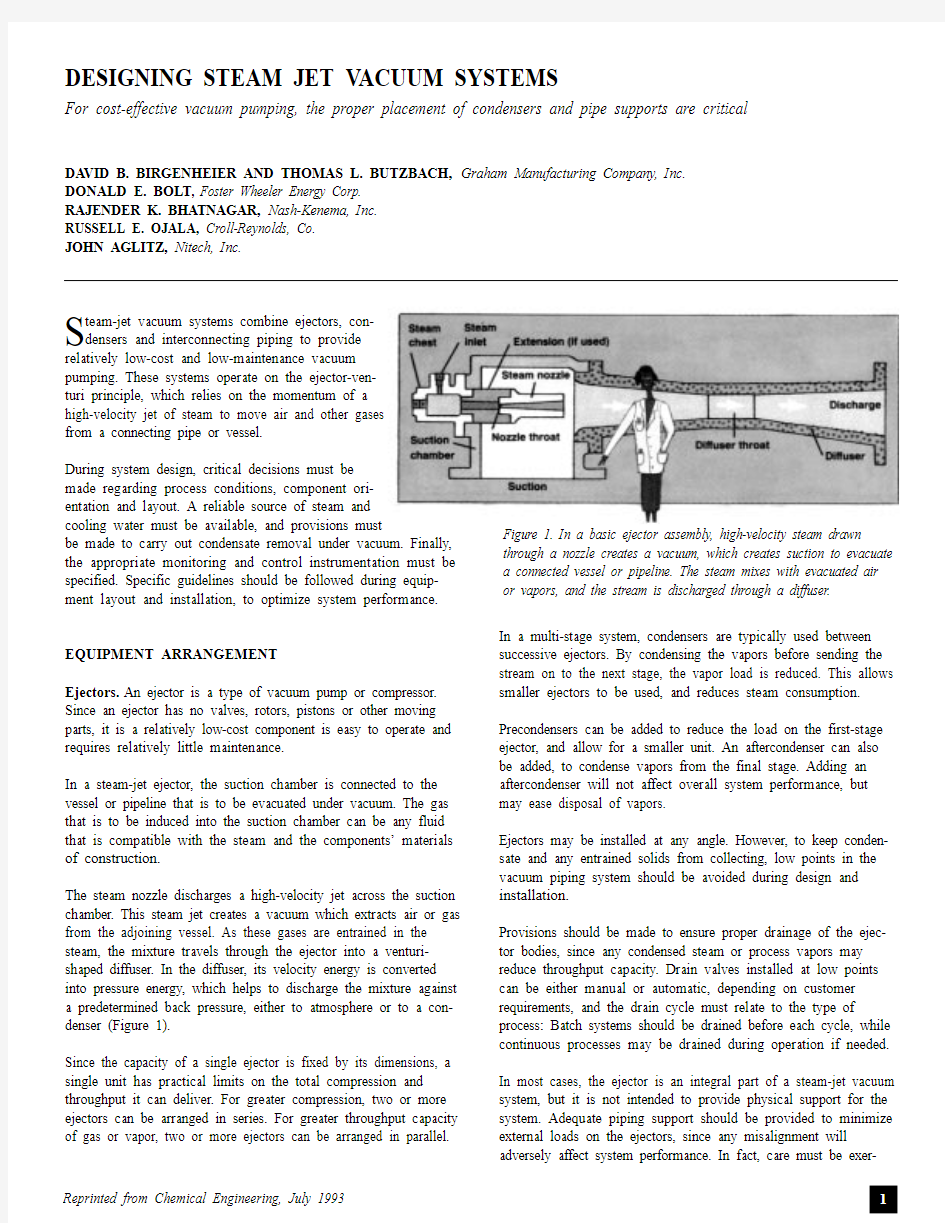
The steam nozzle discharges a high-velocity jet across the suction chamber. This steam jet creates a vacuum which extracts air or gas from the adjoining vessel. As these gases are entrained in the steam, the mixture travels through the ejector into a venturi-shaped diffuser. In the diffuser, its velocity energy is converted into pressure energy, which helps to discharge the mixture against a predetermined back pressure, either to atmosphere or to a con-denser (Figure 1).
Since the capacity of a single ejector is fixed by its dimensions, a single unit has practical limits on the total compression and throughput it can deliver. For greater compression, two or more ejectors can be arranged in series. For greater throughput capacity of gas or vapor, two or more ejectors can be arranged in parallel.In a multi-stage system, condensers are typically used between successive ejectors. By condensing the vapors before sending the stream on to the next stage, the vapor load is reduced. This allows smaller ejectors to be used, and reduces steam consumption. Precondensers can be added to reduce the load on the first-stage ejector, and allow for a smaller unit. An aftercondenser can also be added, to condense vapors from the final stage. Adding an aftercondenser will not affect overall system performance, but may ease disposal of vapors.
Ejectors may be installed at any angle. However, to keep conden-sate and any entrained solids from collecting, low points in the vacuum piping system should be avoided during design and installation.
Provisions should be made to ensure proper drainage of the ejec-tor bodies, since any condensed steam or process vapors may reduce throughput capacity. Drain valves installed at low points can be either manual or automatic, depending on customer requirements, and the drain cycle must relate to the type of process: Batch systems should be drained before each cycle, while continuous processes may be drained during operation if needed. In most cases, the ejector is an integral part of a steam-jet vacuum system, but it is not intended to provide physical support for the system. Adequate piping support should be provided to minimize external loads on the ejectors, since any misalignment will adversely affect system performance. In fact, care must be exer-Figure 1. In a basic ejector assembly, high-velocity steam drawn through a nozzle creates a vacuum, which creates suction to evacuate a connected vessel or pipeline. The steam mixes with evacuated air or vapors, and the stream is discharged through a diffuser.
cised during system design, so that external loads
caused by thermal movement and mechanical load-
ing are minimized.
If the ejector or piping is steam jacketed to prevent
ice buildup, its orientation will affect the operation
and drainage of the jackets. To keep the jackets
from filling with condensate, all inlet and outlet
piping should be installed so that the jacket can be sufficiently drained.
In certain systems, vacuum processes produce vary-
ing amounts of solid carryover, which can deposit
inside the ejector system. During ejector placement,
access for cleaning must be maintained, especially if
the potential for deposits exists.
Condensers. In multi-stage systems, intercondensers
are used between successive ejector stages to reduce
the vapor load on later stages. These units condense
steam and condensable vapors, and cool air and
other non-condensable vapors. Typically, a steam-jet vacuum sys-tem uses either a direct-contact (or barometric) condenser, or a surface condenser, typically a shell-and-tube heat exchanger. For optimal performance, direct-contact condensers must be installed upright and plumb. When the condenser is mounted at barometric elevation (Table, p.120), drainage by gravity is
induced through a sealed tailpipe or drainage leg. Such a con-denser must be placed at a height that is sufficient to prevent flooding under normal operation. Water inlet and outlet piping must be sized according to design flowrates.
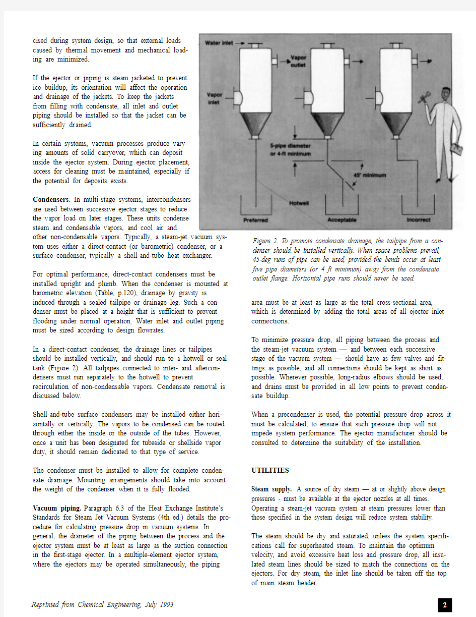
In a direct-contact condenser, the drainage lines or tailpipes should be installed vertically, and should run to a hotwell or seal tank (Figure 2). All tailpipes connected to inter- and aftercon-densers must run separately to the hotwell to prevent recirculation of non-condensable vapors. Condensate removal is discussed below.
Shell-and-tube surface condensers may be installed either hori-zontally or vertically. The vapors to be condensed can be routed through either the inside or the outside of the tubes. However, once a unit has been designated for tubeside or shellside vapor duty, it should remain dedicated to that type of service.
The condenser must be installed to allow for complete conden-sate drainage. Mounting arrangements should take into account the weight of the condenser when it is fully flooded.
Vacuum piping.Paragraph 6.3 of the Heat Exchange Institute’s Standards for Steam Jet Vacuum Systems (4th ed.) details the pro-cedure for calculating pressure drop in vacuum systems. In general, the diameter of the piping between the process and the ejector system must be at least as large as the suction connection in the first-stage ejector. In a multiple-element ejector system, where the ejectors may be operated simultaneously, the piping area must be at least as large as the total cross-sectional area, which is determined by adding the total areas of all ejector inlet connections.
To minimize pressure drop, all piping between the process and the steam-jet vacuum system — and between each successive stage of the vacuum system — should have as few valves and fit-tings as possible, and all connections should be kept as short as possible. Wherever possible, long-radius elbows should be used, and drains must be provided in all low points to prevent conden-sate buildup.
When a precondenser is used, the potential pressure drop across it must be calculated, to ensure that such pressure drop will not impede system performance. The ejector manufacturer should be consulted to determine the suitability of the installation. UTILITIES
Steam supply. A source of dry steam — at or slightly above design pressures - must be available at the ejector nozzles at all times. Operating a steam-jet vacuum system at steam pressures lower than those specified in the system design will reduce system stability. The steam should be dry and saturated, unless the system specifi-cations call for superheated steam. To maintain the optimum velocity, and avoid excessive heat loss and pressure drop, all insu-lated steam lines should be sized to match the connections on the ejectors. For dry steam, the inlet line should be taken off the top of main steam header.
Figure 2. To promote condensate drainage, the tailpipe from a con-denser should be installed vertically. When space problems prevail, 45-deg runs of pipe can be used, provided the bends occur at least five pipe diameters (or 4 ft minimum) away from the condensate outlet flange. Horizontal pipe runs should never be used.
If moisture is present in the steam, a separator and
trap should be used to improve steam quality to bet-
ter than 99.5%. An ejector may work with as much
as 2 or 3% moisture in the steam, but would then
require greater design pressures. Poor-quality steam
will not only threaten the system, but may cause
erosion of the steam nozzle and diffuser.
Cooling water supply. The specified quantity of
water must be supplied to the condenser, and it
must be at or below the design temperatures. If the
volume of cooling water drops, the temperature and pressure of the vapor in the condenser will rise and
the system will cease to operate correctly. A temper-
ature gage at the cooling water outlet should be
used to determine the adequacy of the cooling water
flow.
Condensate removal.Since the operating pressure
of the condenser is sub-atmospheric (under vacuum), collected condensate must be continuously removed. This may be accom-plished by gravity, through a trap or a loop-seal tailpipe, or with
the help of a condensate pump.
Condensate removal through a properly installed tailpipe is the simplest method. The minimum height for the barometric leg is based on the maximum recorded barometric pressure in the sys-tem. The table on p. 120 illustrates the minimum tailpipe height that should be used when the system handles water; if the con-densate is any fluid other than water, height adjustments must be made to account for variable fluid density.
The tailpipe arrangement is crucial. To ensure adequate discharge of the condensate, the system should not contain any horizontal runs of discharge pipe. While the ideal tailpipe arrangement is straight down, site conditions may prevent the installation of ver-tical pipelines. In this case, 45-deg runs of pipe are suitable, as long as the bend occurs no less than five pipe diameters (a mini-mum of 4 ft) away from the condensate outlet flange (Figure 2). T o collect the condensate, the tailpipe outlet is directed into a hotwell or drainage basin. HEI standards specify seal and clear-ance dimensions from the tailpipe outlet to the bottom of the hotwell.
The hotwell should be sized so that the dimensions from the bot-tom of the tailpipe to the point of overflow in the hotwell is large enough to contain at least 1.5 times the volume of condensate contained in the minimum recommended height of the tailpipe. In no case should the seal height be less than 12 in. (Figure 3). In situations where minimum height requirements for a baromet-ric leg cannot be accommodated, a low-level condensate-removal system can be added (Figure 4). This will increase the complexity of the system, since it involves adding a condensate pump, a liq-uid-level control in the collection tank, and a control valve.If during condensate removal the condensate is returned to a col-lection tank operating at a pressure lower than the condenser, a loop-seal arrangement can be used to facilitate condensate removal from the system (Figure 5). This application is typically used with a turbine exhaust condenser.
CONTROL AND INSTRUMENTATION
Basic steam-jet vacuum systems require nothing more than an on-off valve to control the steam and water lines. Additional valves and instrumentation can be added for increased vacuum control, ease of troubleshooting and system optimization.
Suction control. A given steam-jet system has a fixed perform-ance curve of capacity (lb/h) vs. absolute suction pressure (mm or in. Hg absolute). Therefore, a given capacity can be obtained by controlling the suction pressure. Several methods are described below.
Using a control valve, an artificial load can be taken from the dis-charge of any one of the ejectors in the system to produce a recycle control loop. To avoid vacuum leaks, care should be taken in both the sizing and the installation of this control valve (between two levels of vacuum).
The load could also be taken from an external source, such as an atmospheric air bleed, steam bleed from the utility steam, or other process fluids. Condensible vapors are preferred, as their load on subsequent ejector stages can be minimized in the first intercondenser.
In a competing method, a valve can be used in the suction line to create an artificial pressure drop across the ejector. This scheme works well when flow through the suction line is sufficient to Shown here is a typical steam-jet vacuum system used in electrical power generation
cause a pressure drop across the valve’s restricted flow area. When actual flow through the suction line is at least 50% of the design flow, such an artificial pressure drop can usually be induced.The addition of a valve in the suction line is also useful to isolate the vacuum system during startup, shutdown, and troubleshoot-ing. In the event of a vacuum system failure, such a valve can also protect a water-sensitive process, by preventing steam or conden-sate from flowing back into the suction line.
The performance curve of a multistage ejector system varies according to the number of operating stages, and will therefore produce different levels of vacuum with on-off control of select ejector stages. T o control suction, successive stages may only be turned off, starting in succession from the first stage (that which is nearest the process) to the last one (that which discharges to the atmosphere).
A single stage operating alone will produce pressures in the range of about 50 mm Hg absolute up to atmospheric pressure. T wo stages will produce pressures between 10 mm and 100 mm, while three stages will produce between 1 mm and 25 mm.
Finally, suction pressure can be controlled by bringing the whole system in parallel on or off line, or by turning on and off individ-ual ejector elements that have been installed in parallel to the primary stage and use the same interconnections. To isolate indi-vidual elements from the process, a valve must be installed in the steam line to that jet, and in the suction line. A discharge valve may also be added to allow the element to be completely isolated from the system and to be removed for servicing.According to HEI Standards (Paragraph 4.2.2.4.1), the design pressure of the suction chamber and diffuser must be no more than 15 psig (internal), and the unit should be able to withstand full vacuum, unless otherwise specified. During operation, care must be taken when using a discharge valve to avoid pressurizing the ejector bodies with mainline steam pressure. To ensure that this does not happen, the suction valve should be closed first, fol-lowed by the steam valve, and then the discharge valve (use the opposite sequence when turning the system on).
If this procedure cannot be guaranteed, then a pressure-relief valve should be used. It should be sized for the steam consump-tion of the ejector, plus an additional 40%. According to HEI standards (Paragraph 4.1.7.2), the valves should be set to relieve the pressure when it exceeds 15 psig.
T able. To facilitate con-densate drainage under gravity, these minimum heights should be observed when installing a drainage tailpipe from a condenser.A function of the maxi-mum recorded pressures at the site, these heights will differ if the condensate is a fluid other than water.
Figure 3 (left). The Heat Exchange Institute specifies these dimensions when condensate is drained through a tailpipe into a hotwell.
Figure 4 (above). When there is insufficient height to construct a proper barometric leg, a low-level, condensate-removal system can be added. As a condensate pump removes condensate at a constant rate,a mechanical level controller opens and closes a valve, to control the flow of cooling water to the condenser. The solid and dashed lines represent alternative layout options.
INSTRUMENTATION
In a steam-jet vacuum system, the type of instruments, gages and flowmeters used for flow control depend on the specific system being used. Ejector manufacturers should provide critical design data, as well as guidance in selecting and installing the instrumen-tation.
The basic steam-jet vacuum system requires a pressure gage in the main steam line. Typically installed just ahead of the steam-jet system, this gage monitors system performance, and indicates when there is a departure from design pressure.
A steam-pressure gage can be installed on each ejector, when ejec-tors must be turned on and off for control or troubleshooting. Such a gage array will guarantee that each stage of a multistage system is supplied with the correct steam pressure.
Pressure gages may also be useful over time if the mainline steam pressure varies over the system and must be controlled at each ejector. Such gages are helpful during troubleshooting, since they may indicate plugged steam lines or nozzles, or faulty valves.
A flowmeter can be added to maintain the specified flow to the condenser. Water-temperature gages on the inlet and outlet water lines of each shell and tube condenser will indicate when the maximum outlet temperature has been exceeded, which may demonstrate insufficient water or excess steam load. Such gages will also alert the operator to a decrease in the temperature, which may indicate a fouled condition.
Most systems will include a vacuum gage to moni-
tor absolute pressure at the process vessel. This
gage may not be able to measure the pressure of
the overall vacuum system, since other devices may
be inline between the two.
When troubleshooting a multistage steam-jet sys-
tem, it is desirable to have suction pressure
measured at each ejector. In these situations, a
portable vacuum gage is helpful.
There are many self-compensating, absolute-pres-
sure gages available. Users are cautioned against
relying on a compound, bourdon-tube type gage,
which will not give accurate results for vacuum lev-
els over 28-in. Hg. If a mercury manometer is
used, it must be corrected for actual barometric
pressure.
PACKAGING
The components of a steam-jet vacuum system can be conve-niently packaged or skid mounted. The package can be a simple arrangement that includes valves, interconnecting piping and util-ity connections, or it can be a more complex assembly, such as a complete turnkey system.
Modular packaging of a steam-jet assembly must be designed so that forces and moments are ultimately transferred to support points. If loads are not transferred safely to suitable anchorage points, a failure or misalignment of the equipment can occur. In particular, external pipe connections should not impose any addi-tional forces or moments to the steam, vapor and water piping. TROUBLESHOOTING TIPS
There are two basic types of malfunction in an ejector system: those caused by external influences or equipment, and those caused by the ejectors or condensers themselves. It is important that only qualified personnel, using proper equipment, perform testing.
External problems. To locate the source:
?Determine whether any changes have been made to the process served by the steam-jet vacuum system ?Determine whether the pressure and temperature of the steam or the condensing water have changed with respect to system specifications
?Determine whether any recent process changes have been made, which may have altered the feed rate of the vapor
stream evacuated from the process vessel
Figure 5. When a loop-seal arrangement is used for condensate removal, the height of the loop must be in accordance with manufacturer’s’instructions, to maintain the desired seal. Shown is a typical loop-seal drain for an intercondenser, and a condensation trap for an aftercon-denser.
?Determine whether the problem developed gradually or sud-denly. As a general rule, a gradual loss of vacuum is due to
changes or the deterioration of the vacuum system, while a
sudden loss of vacuum usually is due to a change in utilities, increase in backpressure, or system leak
?Review the unit’s recent maintenance history, and make note of any recent modifications
?Review any records of previous problems
Once these steps have been followed, and it has been determined that the correct flow, steam pressure and coolingwater tempera-ture are in use, and that the pressure at the discharge of the
final-stage ejector is not excessive, the next step is to determine whether the operational problem resides within the ejector system itself.
Internal problems. T o pinpoint malfunctions, a step-by-step pro-cedure should be followed to assess each component. First, the ejector should be isolated by means of “blank off” plate at the suction inlet of the first-stage ejector. With all units operating while the plate is in place, the ejector will evacuate the first-stage suction chamber to the minimum pressure that the ejector is capable of producing.
The following shut-off pressure can be expected (each is approxi-mate, and will vary with the system):
?Single-stage ejector50 mm Hg absolute (A)?Two-stage ejector4-10 mm HgA
?Three-stage ejector0.8-1.55 mm HgA ?Four-stage ejector0.1-0.2 mm HgA
?Five-stage ejector0.01-0.02 mm HgA ?Six-stage ejector0.001-0.003 mm HgA
If this test indicates that the ejector is operating at its approxi-mate shut-off pressure, then it can be assumed that the ejector will operate satisfactorily along its entire performance curve. Further troubleshooting would then be required on the vacuum system upstream to the ejector.
However, if the expected shut-off pressure is not obtained or is unstable, then the troubleshooting should be confined to the ejec-tor system. A hydrostatic test is recommended to check for air leakage. Caution should be exercised:Before carrying out such a test, determine whether the system is designed to carry the extra pressure and weight of the water required to perform the hydrotest.
If a hydrotest cannot be used, a low-pressure air test, using air pressurized to roughly 5 psig, can determine if the ejector system has a leak. Once again, system specifications should be checked to ensure that the unit will tolerate such pressure.
During the test, a soap solution or spray should be applied to all joints, valve packings and other potential leak sites. If an air leak is present, the soap solution will form a bubble over the leak.For systems operating under vacuum, ordinary shaving cream is another inexpensive indicator. When applied to all joints and potential leak joints, the cream will be sucked into the opening, and the leakage source will be easily observed.
If the hydro, air, or vacuum tests have not indicated any leakage, the next step is to check the internals of each component for damage or wear. Dismantle the ejector and check for deposits, scaling of internal parts, and wear in the nozzle and diffuser.
If the system uses multistage ejectors, begin with the final-stage unit. Check the threads of the nozzle for telltale white or tan streaks, which indicate a steam leak through the threaded connec-tion.
Remove deposits from the suction chamber and make sure it is not cracked, rusted, or corroded. Shine a small light through the diffuser to make sure it is completely free from scale and is not pitted, grooved, or cut.
After all stages and intercondensers have been cleaned, the throat diameters or the nozzles and diffusers should be measured as accurately as possible. Compare these with the original dimen-sions of the throat diameters, supplied by the manufacturer, to determine wear.
If either diameter is larger than the original equipment specifica-tions, calculate both original and present throat areas, and determine the percentage increase in areas. If the percentage increase is greater than 7%, the nozzle or diffuser will have to be replaced before satisfactory operation can be expected. Even if the percentage increase in area is only 5%, replacement nozzles or dif-fusers should be ordered, prepare for an inevitable upgrade. Edited by Suzanne Shelly
HEAT EXCHANGE INSTITUTE
The Heat Exchange Institute (HEI) is a non-profit trade association committed to the technical advancement, promotion and understanding of a broad range of util-ity and industrial-scale heat exchange and vacuum apparatus.
The Institute concentrates its efforts on the manufacturing and engineering aspects of steam surface condensers, closed feedwater heaters, power plant heat exchangers, liquid ring vacuum pumps, and steam jet ejectors.
The Institute’s membership is comprised of major U.S. manufacturers of heat exchange and vacuum apparatus. These companies recognize the need for industry standards which reflect the growth in technology.
Acknowledged worldwide as the leading standards development organization for heat exchange and vacuum apparatus, the Institute maintains its commitment to the technical advancement of the industry it serves.
steam教育理念的九要素
steam教育理念九要素 虽然STEAM教育以不同的方式在不同的国家和地区进行的,有一个共识,即主题的课堂教育STEAM的不可缺少的主要途径。 在这样的共识,有必要借鉴国外经验借鉴。那么,如何使用引用来进行跨学科的教学和STEAM教育,这样才能更好地提高课堂教学质量,培养学生核心素养? 1.组织教学内容与全面性的目的 首先,我们应与现实生活相连接。其次,我们应该整合跨学科的教学内容与全面性的目的。通过这种方式,STEAM教育的渗透已基本完成。什么是一些良好的综合主题?地理环境,自然灾害,健康与疾病,科学和技术发展等方面都较好的综合主题。 例如,在13和14世纪,当蒙古汗国建立横跨欧亚大陆一个伟大的帝国,怎么黑死病爆发在中国蔓延到欧洲,并导致了一半的人口欧洲的急剧减少,直到150 年后,原有的经济高峰恢复。而解决这个问题,还可以扩展知识,经济,历史,社会学,生物学,地理学等。当学生们解决这些实际问题,他们可以学习如何运用自己的知识。 首先,情感态度与价值观能滋润; 其次,养成健康生活的意识和能力,而不是简单地获取知识; 其次,要制定解决问题的能力和多学科知识的综合应用能力,并锻炼理性思维,科学探究和技术应用能力。 STEAM教育学生交流讨论中 2.在课堂强调实践教学 STEAM教育有一个很大的特点,那就是,注重实践,这也是整合多学科的教学方法的出发点。 例如,在理科班,学生被允许在生产月历的合作,注重科学概念“月相”的研究,集成工程,技术,数学和艺术的研究; 在艺术班,学生被允许树叶添加到一个死树,专注于艺术绘画活动,将科学,数学,工程和技术的研究。 3.评估学生的学习 在评价内容上,评价者不仅要注意学科知识,科学的解释,其转让和应用的了解,同时也注重培养学生的劳动意识,技术应用,人文积淀,审美情趣等成就。鉴于技术的应用,教师要全面评价技术与社会,设计和系统,信息和通信技术,以及
学习steam教育理念的心得体会
学习steam教育理念的心得体会 于4月29日下午学校召开了STEAM教育研讨会。本次活动还特别邀请到了一名STEAM教育研究专家—哈佛大学教育研究院研究员江学勤博士。STEAM代表科学(Science,技术(Technology),工程(Engineering),艺术(Art),数学(Mathematics)。STEAM教育就是集科学,技术,工程,艺术,数学多学科融合的综合教育为了让我们充分理解STEAM教育的理念,并更好地利用STEAM教学的理念 研讨会上,江博士以如何用STEAM来培养学生的创造力为主题,围绕什么是创造力、什么是STEAM、怎样开展STEAM教学、怎样培养学生创造力等方面进行了精彩的讲座。江博士还现场运用运用生动活泼的小游戏如怎样指导学生的跳绳为例,展现传统教学与未来教学的不同,深入浅出地告诉我们未来的教育应该是怎样的教育。 通过这次学习我收获颇多:常规教学有着逻辑缜密、知识系统的优势,能够有效调动学生动手能力与合作精神,但在人工智能时代常规课堂教学不利于培养学生科学思维。教学需要运用科学思维赋予学生解决问题的能力,而STEAM教学的首要目标是培养学生的科学思维,形式以游戏化模式为主,更能激发学生自身能量,在STEAM教学中考核标准贯穿各项环节,易于学生养成创作精神与数学学科核心素养能力。 通过现场课堂观摩蒋玉芹老师的彩虹课堂和聆听江博士讲座,更新了我对"STEAM"教育的认识。更进一步了解到跨学科教学,学科渗透与融合已是未来教育的发展趋势,对于培养学生的综合学习能力和创新精神,以及增强教师的专业素养都起着至关重要的作用。 与此同时,创新意识的培养也不容忽视。"Nothing is wrong in creation."现代化教学背景下的课堂要求老师不能扼杀学生的质疑精神,而要善于挖掘和培养学生的创新品质,创新思维和创新意识,不再一味说Yes, 而要勇于说No!不得不说,这对于每一位老师来说,既是一种挑战,也是一种机遇!
基于我国STEAM教育理念的美术融合课程初探
龙源期刊网 https://www.360docs.net/doc/5d7580296.html, 基于我国STEAM教育理念的美术融合课程初探 作者:吴萍萍王燕 来源:《报刊荟萃(上)》2018年第07期 摘要:STEAM是美国政府提出的教育倡议,即加强美国关于科学(Science)、技术(Technology)、工程(Engineering)、艺术(Art)、数学(Mathematics)跨学科方式综合 多学科的相关知识,培养学生的实践能力与问题解决能力。立足于国内实际的教育发展现状,许多国内研究者和团队对国内外教材、创新理念进行了重构,开展了STEAM教育一系列本土化的实验性研究,STEAM将STEM加以升级;它能让孩子们把所学的科学、技术、数学、工程等科学与艺术结合起来,并通过艺术的方式来表达。在此背景下,中国教师如何利用“美术”这一学科的独特作用,在学生初入校园的小学阶段就为学生搭建一个网状、立体的知识网络,将美术与其它学科的知识、技能和素养在小学课堂里面进行整合,开展基于真实问题解决的探究学习和基于设计的学习。最后本文分析了STEAM教育发展本土化的阻碍,对STEAM教育在我国国内的发展提出了几点建议。 关键词:STEAM教育;Arts;美术课程;反思 一、对STEAM教育理念的追本溯源 STSTEAM与STEM已经被中国的教育界很多学者所熟知,很多一线教师都对此开展来研究与教学工作。对于STEAM教育理念的一般理解,STEM加Arts等于STEAM,艺术提供一个不同的通道,帮助人类了解复杂发社会。STEAM教育是近几年国际科技教育领域新兴的研究和实践范式,逐渐被越来越多的人认可和接受。STEAM教育关注对科学知识的解释,科学探究的实践,以及工程设计的结合。以美国为首加拿大、韩国、以色列等国的学校在国际上已逐渐掀起一股STEAM教育热潮。因此,变革教育组织形式、建设科技创新类新课程、培养具有综合科技素养和深度创新能力人才的教育新范式——STEAM教育,将成为知识经济时代一种全球性的科技艺术教育战略。 二、基于STEAM教育理念的美术课程的设想 美术融合课程定位是以艺术领域内的学科融合和艺术融合其他学科构建课程体系;是基于真实情景项目化探究性学习开展教学;以培养学生艺术素养和21世纪技能为目标;积极应对保护文物、传承中华优秀传统文化、立德树人等我国当下教育诉求,为实现中华民族伟大复兴的中国梦助力。在美术融合课程里面,Arts在某一项具体的学科当中他是融合自身领域内的学科,Arts是一个大艺术的范畴,或者说它融合其他一些学科而不仅仅是现有的一些美术,艺术只是起到一些美术作用或者说是一个辅助手段,在我的理解里他是一个三维的坐标轴,即艺术诸多门类、其他学科及当下的教育诉求。这三个方向都是可以无限扩展的,因为任何学科以及
steam教育理念的九要素
蒸汽教育的六个核心特征是什么?我们来看一下。 (1)跨学科 将知识划分为学科有助于进行科学研究,深入探索自然现象的奥秘,以及将知识划分为易于教授的模块,但这并不能反映我们生活世界的真实性和兴趣。因此,学科教学(如物理,化学)在高度发展的科学,技术和工程学中显示出极大的劣势。针对这一问题,理工科教育已经出现了取消学科划分,实行综合教育的趋势。结果,蒸汽教育应运而生,跨学科是其最重要的核心特征。 (2)艺术性 蒸汽中的“a”在狭义上指美术和音乐。从广义上讲,它包括艺术,音乐,社会,语言和其他人文艺术,实际上代表着蒸汽所强调的艺术和人文属性。蒸汽教育的艺术性强调,在自然科学教学中,学习者应更加重视人文社会科学,例如在教学中增加科学,技术或工程史,以激发学生的兴趣,增加他们的学习兴趣。了解蒸汽与生命之间的关系,
并改善他们对蒸汽相关决策的判断;另外,在对学生设计作品的评价中,增加了审美维度的评价,以提高学生作品的艺术性和审美感。 一般而言,蒸汽教育的艺术性基于数学元素,并从工程和艺术的角度解释科学和技术。 (3)体验式 Steam教育不仅提倡通过自学或教师的教学来获取抽象知识,而且还强调学生的动手,脑力劳动和参与学习过程。Steam为学生提供了动手学习的经验。学生运用他们的数学和科学知识来处理现实世界中的问题,创建,设计,构造,发现,合作和解决问题。因此,蒸汽教育具有经验的特征。在参与和体验知识的过程中,学生不仅获得了结果知识,而且还获得了解决项目问题过程中所包含的过程知识。 (4)情境 Steam教育具有情境特征。它强调学生应该获得在上下文中应用知识的能力。同时,他们可以理解和识别不同情况下的知识表现。即,他们可以根据知识的背景信息来识别
STEAM教育理念
steam (教育理念) STEAM代表科学(Science),技术(Technology),工程(Engineering),艺术(Arts),数学(Mathematics)。STEAM教育就是集科学,技术,工程,艺术,数学多学科融合的综合教育。 STEAM由来 不难理解,STEAM是这五个单词的缩写:Science(科学), Technology(技术), Engineering(工程), Arts(艺术), Maths(数学)。有人称这个STEAM教育打破学科界限很好玩,比如技术和工程结合,艺术和数学结合,科学和工程结合…… 教育理念 STEAM是一种教育理念,有别于传统的单学科、重书本知识的教育方式。STEAM是一种重实践的超学科教育概念。任何事情的成功都不仅仅依靠某一种能力的实现,而是需要介于多种能力之间,比如高科技电子产品的建造过程中,不但需要科学技术,运用高科技手段创新产品功能,还需要好看的外观,也就是艺术等方面的综合才能,所以单一技能的运用已经无法支撑未来人才的发展,未来,我们需要的是多方面的综合型人才。从而探索出STEAM教育理念。 STEAM教育理念最早是美国政府提出的教育倡议,为加强美国K12关于科学、技术、工程、艺术以及数学的教育。STEAM的原身是STEM理念,即科学(Science)、技术(Technology)、工程(Engineering)、数学(Mathematics)的首字母。鼓励孩子在科学、技术、工程和数学领域的发展和提高,培养孩子的综合素养,从而提升其全球竞争力。近期加入了Arts,也就是艺术,变得更加全面。 STEAM教育在美国的重要性不亚于中国的素质教育,在美国大部分中小学都设有STEAM教育的经费开支,而STEAM也被老师、校长、教育家们时时挂在嘴边。在STEAM 教育的号召下,机器人、3D打印机进入了学校;奥巴马也加入了全民学编程的队伍,写下了自己的第一条代码;帮助孩子们学习数学、科学的教育科技产品层出不穷;而且这五个学科,技术和工程结合,艺术和数学结合,打破常规了学科界限。
基于STEAM教育理念的创新课程实践研究
ft代做疔2019/4A 专题研究 基于STEAM教育理念的创新课程实践研究 文/上海市上海中学国际部姚昇华刘炼 【摘要】本文介绍了在STEAM教育理念的指导下,上海市上海中学国际部初中段构建了以创新意识养成、创新过程体验和创新能力培养为核心的创新课程。通过分层次的创新课程学习,学生的综合素养得以发展。其中,硬件、软件的同步构建,专业化、个性化的学习指导是创新课程顺利实施的有力保障。 【关键词】STEAM教育理念创新课程 STEAM代表了科学、技术、工程、艺术、数学,是一种培养学生综合素养的教育。其本质是以培养创新精神和创新能力为着眼点,以综合素养的培养为导 (上接第5页) 与课程的学生进行问卷调查,三个学期共收到240份有效问卷。调查结果显示,STEAM课程获得了学生的广泛认可,95.9%的学生希望继续深入学习自己所选择的STEAM课程,99.2%的学生希望学校能够开设更多的STEAM课程。学生觉得通过STEAM课程的学习自己的多方面能力得到了提升,其中“问题解决能力”(59.4%)、“创新思维”(48.4%)、“团队合作能力”(44.3%)排在前三位。STEAM课程的跨学科领域的知识技能学习对于学生未来的职业生涯发展很重要。从学生未来想从事的职业来看,选择STEAM课程的学生,更多地想从事跨学科领域(36.5%),其次为工程领域(2&3%)和科学领域(23.8%)。这一实践效果的形成除了学校已有的课程体系支撑之外,更多的得益于师生学术共同体的构建与数字化创新实验室的建设。调查显示,有74.9%的学生认为学校STEAM课程的开设效果离不开“学生与教师共同研究的学术探究氛围”,68%的学生认为学校STEAM课程的开设与现代化创新实验室建设紧密相关。 结合课程实施中积累的学生反馈和教学反思,在STEAM课程实践过程中还需要关注如下三个问题。 一是关注课程的衔接性。STEAM课程不应是架空在学校课程体系之上的,而应与校内课程有机融 合。作为STEAM课程的铺垫,学校宜在常规分科课程之外,设置相应的STEAM共用技术课程,奠定工程和技术知识基础。STEAM课程的延伸一般为基于课题向,以学科整体化和系统化为主要特征,以培养具备21世纪技能的公民为理念的课程体系开发和设计。上海中学国际部初中段的创新体验与实践课程便是 (下转第7页) 研究的专门课程,让学生能够独立完成课题研究,体 验更为完整的科学探究过程。STEAM课程要想更好地提升学生的职业能力,还需要与大学、企业进行全 面合作,打通职业生涯规划的全路径。 二是关注课程的开放性。项目涉及的内容是开放的,不仅仅局限在这五门学科领域,可以向更多的领域拓展,引入学科之外的视角,会更有助于STEAM 课程目标的实现。课程的场地是开放性的,不仅仅局限在一个教室、一个实验室,甚至可以跨越学校和国界,整合线上和线下,让学生从更多的角度去体验真实的问题解决过程。 三是关注课程的生长性。跨学科的STEAM的生长性表现:课程的内容是动态的,教师要不断根据学生的表现及过程中遇到的问题调整课程内容;项目的结果是开放性的,并没有预设的答案。STEAM课程的实施重要的是留给师生充足的创造空间,鼓励学生勇于探索,大胆尝试,不断萌发生长出新的解决方案。探 参考文献: [1]吕延会.STEAM教育的核心精神[J].当代教育科学,2017(5). [2]杜文彬,刘登环.走向卓越的STEAM课程开发— —2017美国STEAM教育峰会述评[J].开放教育研究,2018(02). 6
STEAM教育带给我们的启示
STEAM教育带给我们的启示 科技的进步和越来越智能化的生活也在悄然间改变着人们的观念。而家长们的观念一旦改变,最直接体现在孩子教育上,这和中国传统文化密不可分,中国人都崇尚有钱用在刀刃上,在家长们眼里,孩子的教育就是刀刃。格物斯坦小坦克来说说stem教育给我们的启示。 随着少儿编程的火爆,更多的家长也开始注意孩子动手能力的培养。STEAM教育的流行带给教育领域一些新的启示,可以通过动手操作来学习理解相关的知识点,通过做来学。在提升孩子的动手能力和逻辑理解能力同时让孩子学到知识,STEAM成为了一种新的教育形式。STEAM教育的快速蹿红主要原因还是他本身的教育形式,受到广大师生的欢迎。学习与实践相结合是STEAM 的优势所在。将需要学习的知识融入到实操的内容中,通过动手来完成学习。在轻松愉快的环境中完成学习。 STEAM教育到底能带给孩子什么?首先,是给孩子带来很多科学知识,STEAM教育本身就是有多领域多学科汇聚而成的课程,可以通过动手操作来学习相关的知识点,同时锻炼孩子的动手能力。 其次,可以通过STEAM教育开发孩子的想象力,孩子可以通过配套的工具将自己想象中模型的样子搭建出来,对于孩子的逻辑思维能力,动手能力也是有直接的提升。STEAM教育的引入到教育领域,本身是教育改革的需要,也是孩子在开发更多潜在能力的助手。 随着教育改革的深入,类似STEAM教育的新领域会更多引入教育领域,服务于教育。在素质教育的今天培养孩子综合能力是家长和教育领域要去探索的课题。相对于传统教育,STEAM教育给了我们很多的启示。相对于要求标准答案的传统教育,STEAM教育给了孩子更多的发挥空间,开拓了他们的想象力。 希望有很多更好的教育理念能引入我们的教学,给孩子带来更多不一样的学校体验。
steam教育理念的九要素
steam教育的六大核心特征是什么?让我们看看。 (1)跨学科 将知识划分为学科有助于科学研究、深入探索自然现象的奥秘、将知识划分为易于传授的模块,但这并不能反映我们生活世界的真实性和趣味性。因此,在科学技术和工程高度发达的情况下,学科教学(如物理、化学)表现出很大的弊端。针对这一问题,取消理工科教育学科划分,实行综合教育已成为大势所趋。因此,蒸汽教育应运而生,跨学科是其最重要的核心特征。 (2)艺术的 steam中的“a”是指狭义的艺术和音乐。广义地说,它包括艺术、音乐、社会、语言等人文艺术,实际上代表了Steam所强调的艺术性和人文性。steam教育的艺术性强调,在自然科学的教学中,学习者应更多地关注人文社会科学,如在教学中加入科学、技术或工程历史,以激发学生的学习兴趣,提高他们的学习兴趣。了解steam与生活的
关系,提高学生对steam相关决策的判断能力;另外,在学生设计作品的评价中,增加了审美维度的评价,提高了学生作品的艺术性和美感。 一般来说,蒸汽教育的艺术性是以数学元素为基础,从工程和艺术的角度来解释科学和技术。 (3)经验的 Steam教育不仅提倡通过自学或教师教学获得抽象知识,而且强调学生的动手能力、脑力劳动和参与学习过程。Steam为学生提供实践学习体验。学生运用他们的数学和科学知识处理现实世界的问题,创造,设计,构造,发现,合作和解决问题。因此,蒸汽教育具有体验性的特点。在参与和体验知识的过程中,学生不仅获得了结果知识,而且获得了解决项目问题所涉及的过程知识。 (4)形势 Steam教育具有情境特征。它强调学生应具备在语境中运用知识的能力。同时,他们能够理解和识别知识在不同情境下的表现。也就是说,他们可以根据知识的背景信息
STEAM教育如何转变中国的教育理念
回首过去的国内教育体系,传统的教育方式一直被延续,几乎从未改变过的学习方式。如今科技时代的发展,在教育中缺少了创新与进步。然而国外的教育理念,已经开始更加自由、开放的学习方式,进而升级为以创意为主导的新型教育方案,这种方案模式受到了前所未有的欢迎,甚至让美国的现任总统奥巴马都在反复地强调,这种教育方案是今后美国的教育发展重要方向,不仅如此,还要在其中加大对科学、技术、工程和数学教育的投入,并且开拓出学生的科技理工素养。 STEAM教育,其实正是目前世界各个国家中在极力推行的教育理念,即推崇以培养孩子的探索和创新能力为主导,即加强关于科学(Science)、技术(Technology)、工程(Engineering)、艺术(Arts)以及数学(Maths)的教育。学生可以在兴趣学习的同时实现创新的个性化,让“创造思维”与“创新能力”取代传统的课堂式学习。SETAM教育理念也更加注重与前沿技术的相互结合,具有独特创意的科技技术引入到教育中,将让科技成为创新教育的推动力。 中国的教育模式由于长久以来所形成的特殊性,无法向国外那样开放的实行自由沟通的教育方式,单也在逐步的寻找着适合改变传统教育理念的方法,及打
开学生创新创意思想大门的钥匙。而在今年的第十二届全国人民代表大会第四次会议中,我们发现时下全球火热的“3D打印”被列入“十三五”国家规划纲要,国家领导人也曾在国内、国际的会议中,强调“3D打印技术”的重要性。3D 打印技术具有高度自由的创新理念,与STEAM倡导的教育方式相互结合,目前已经成为了各中小学争相开展的教育课程,这种新的教育模式,在国内掀起了一股以创意为主导的校园课程。 转变传统的授课模式,总结STEAM教育国内外优秀的3D打印课程的开课经验,结合3D创意笔简单易操作的使用方式,让学生们无需通过长时间的专业学习也能通过立体思维表达制作3D创意的想法,通过想象力与3D创意笔的结合,将无穷的设计想法和无限制的实体制造完美地结合起来,培养学生们关于批判性思维,让其具备分析与问题解决;协作能力,可以跟其他人一起分工合作完成任务;沟通能力,向他人通过不同媒介方式,展示自我想法;创造能力,有自己的想法并实际执行。在短短的课程中,将想象中的物体形象转变为立体的现实作品,所见即所得。在课堂中不仅可以让孩子们时刻处于兴奋的创造状态中,同时让学校与家长们在看到该种教育理念所具有的实际意义后,对STEAM教育将3D设计打印技术带入中小学课堂而充满期待。 STEAM教育培养的是从小开始建立的创新思维模式,由内而外地去发现新想法,课程的建立,并不仅仅是需要一个打印成果,在课程中转化思维,完成创新理念的延展与发挥,才是课程想要达到的真正效果。 在此,建议大家可以了解一下昂立教育-青少儿教育成长专家。 昂立教育,专注于幼少儿教育培训和教学产品开发,由上海昂立教育投资咨询有限公司负责推广发展。目前上海共建有近150个校区,全国1000多所学校,