Depth Estimation and Image Restoration
Depth Estimation and Image Restoration Using Defocused Stereo Pairs
A.N.Rajagopalan,
S.Chaudhuri,Senior Member,IEEE,and
Uma Mudenagudi
Abstract—We propose a method for estimating depth from images captured with a real aperture camera by fusing defocus and stereo cues.The idea is to use stereo-based constraints in conjunction with defocusing to obtain improved estimates of depth over those of stereo or defocus alone.The depth map as well as the original image of the scene are modeled as Markov random fields with a smoothness prior, and their estimates are obtained by minimizing a suitable energy function using simulated annealing.The main advantage of the proposed method,despite being computationally less efficient than the standard stereo or DFD method,is simultaneous recovery of depth as well as space-variant restoration of the original focused image of the scene.
Index Terms—Defocus,stereo,disparity,Markov random field,blur identification, depth recovery.
?
1I NTRODUCTION
A N important area of research in computer vision is the recovery of 3D information of a scene from2D images.In humans, stereoscopically presented images provide information about depth.Julesz[1]showed that random dot stereograms provide a cue for disparity even when each image does not provide any high-level cue for depth.Interestingly,Pentland[2]reported a finding that the gradient of focus inherent in biological systems is also a useful source of depth information.
Binocular stereo matching is,in general,ambiguous if the matching is evaluated independently at each point purely by using image properties.All stereo matching algorithms examine candidate matches by calculating how much support they receive from their local neighborhood.Marr and Poggio[3]proposed a cooperative stereo algorithm based on a multiresolution framework.Barnard and Thompson[4]proposed a feature-based iterative algorithm to solve the correspondence problem.A large number of papers have appeared in the literature on stereo analysis and a review of them can be found in[5].Conventional stereo analysis assumes an ideal pin-hole camera model which offers an infinite depth of field. However,any practical camera system will produce depth-related blurring.In the depth from defocus(DFD)technique,two images of an object,which may or may not be focused,and acquired with different camera settings,are processed to determine depth.The relative blur between the defocused images serves as a cue for depth. Unlike stereo,DFD uses a real aperture camera model(which is more practical).Since the early works of Pentland[2],several approaches [6],[7],[8],[9],[10]have emerged for solving the DFD problem.A comparative analysis of DFD and stereo can be found in[11].Related works on defocus blur estimation in conjunction with image motion/ disparity are addressed in[12],[13],[14],[15].
It is well-known that stereo yields accurate estimates of depth but the depth map is sparse since correspondence can be obtained with confidence only at prominent feature points.On the other hand,DFD gives a dense depth map but the accuracy of depth estimates are generally inferior to that of stereo-based methods.Estimates of depth from defocus can be particularly poor in severely blurred regions[8]. In this paper,we relax the assumption of a pin-hole camera model and propose an algorithm to recover depth from defocused stereo (DFDS)pairs of images.Defocus and stereo cues are fused to obtain improved dense estimates of depth.The additional constraints provided by stereo help in refining the estimates of depth over those obtained using DFD alone.Tsai et al.[16]have also proposed a scheme for integrating stereo and defocus.But,they use estimates from DFD to only initialize their stereo matching algorithm.
In stereo,the disparity is directly related to depth,while in DFD, it is the blur parameter that relates to depth.Hence,disparity can be expressed in terms of the blur parameter,the lens settings,and the base-line distance.This information is used to fuse the two methods, thereby deriving the advantages of both the methods.In DFD,since the blur depends on the depth of the scene,the point spread function (PSF)in turn becomes a function of depth.For simplicity,most techniques assume local space-invariance and compute depth. However,this can lead to poor estimates of depth due to the image overlap problem[9].We model the depth and the focused image of the scene individually as Markov random fields(MRFs).Our approach avoids windowing and addresses the DFDS problem in its generality.Given two defocused stereo pairs of images,we obtain a focused image of the scene and a dense depth(blur/disparity)map. An important advantage of our method is that it not only recovers estimates of depth but also performs effective space-variant image restoration.The performance of the method is validated on synthetic as well as real images.The accuracy of depth estimates is superior compared to those obtained from DFD or the stereo method.A dense depth map is estimated without correspondence and interpolation.The quality of the restored image is also quite good.
Section2describes the framework for fusing defocus and stereo.In Section3,we discuss the proposed approach for solving the DFDS problem.Experimental results are given in Section4 while Section5concludes the paper.
2F USION OF D EFOCUS AND S TEREO
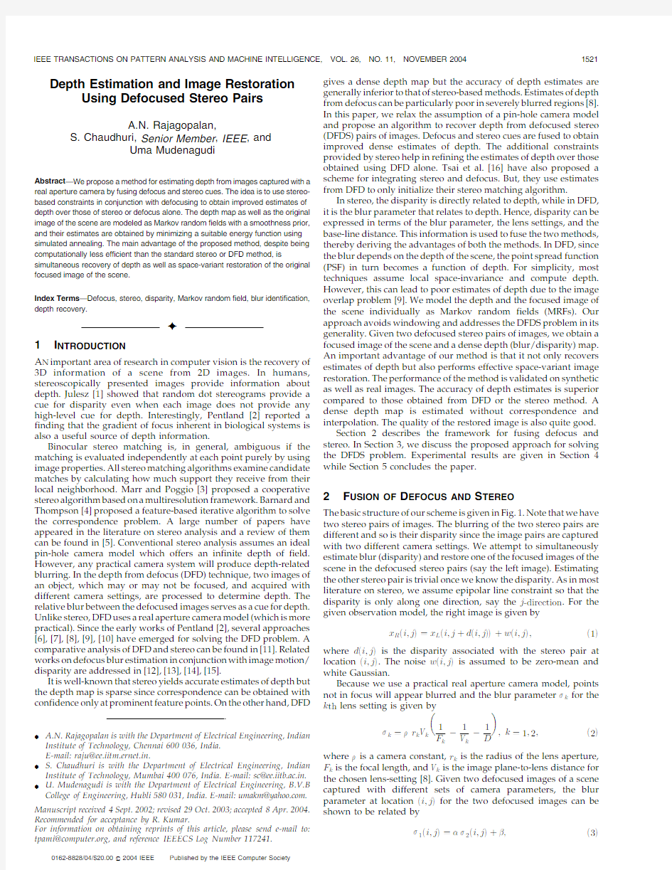
The basic structure of our scheme is given in Fig.1.Note that we have two stereo pairs of images.The blurring of the two stereo pairs are different and so is their disparity since the image pairs are captured with two different camera settings.We attempt to simultaneously estimate blur(disparity)and restore one of the focused images of the scene in the defocused stereo pairs(say the left image).Estimating the other stereo pair is trivial once we know the disparity.As in most literature on stereo,we assume epipolar line constraint so that the disparity is only along one direction,say the j-direction.For the given observation model,the right image is given by
x Rei;jT?x Lei;jtdei;jTTtwei;jT;e1Twhere dei;jTis the disparity associated with the stereo pair at locationei;jT.The noise wei;jTis assumed to be zero-mean and white Gaussian.
Because we use a practical real aperture camera model,points not in focus will appear blurred and the blur parameter k for the k th lens setting is given by
k? r k V k
1
k
à
1
k
à
1
;k?1;2;e2T
where is a camera constant,r k is the radius of the lens aperture, F k is the focal length,and V k is the image plane-to-lens distance for the chosen lens-setting[8].Given two defocused images of a scene captured with different sets of camera parameters,the blur parameter at locationei;jTfor the two defocused images can be shown to be related by
1ei;jT? 2ei;jTt ;e3T
. A.N.Rajagopalan is with the Department of Electrical Engineering,Indian Institute of Technology,Chennai600036,India.
E-mail:raju@ee.iitm.ernet.in.
.S.Chaudhuri is with the Department of Electrical Engineering,Indian Institute of Technology,Mumbai400076,India.E-mail:sc@ee.iitb.ac.in. .U.Mudenagudi is with the Department of Electrical Engineering,B.V.B College of Engineering,Hubli580031,India.E-mail:umakm@https://www.360docs.net/doc/5d11535874.html,. Manuscript received4Sept.2002;revised29Oct.2003;accepted8Apr.2004. Recommended for acceptance by R.Kumar.
For information on obtaining reprints of this article,please send e-mail to: tpami@https://www.360docs.net/doc/5d11535874.html,,and reference IEEECS Log Number117241.
0162-8828/04/$20.00?2004IEEE Published by the IEEE Computer Society
where
?r1V1
r2V2
and ? r1V1
1
F1
à
1
V1
à
1
F2
t
1
V2
:
Thus, and are known constants that depend on the camera settings.Most DFD methods assume a Gaussian-shaped blur model
for the camera PSF,i.e.,hei;jT?1
2 2expeài2tj2
2 2
T.Though the Gaussian
blur is of infinite extent,a finite spatial extent approximation (?3 pixels)is reasonable to assume for the Gaussian window.Note that the PSF is space-varying since (as given in(2))depends on the depth of the scene for a fixed camera setting.
From standard stereo analysis,we know that the deptheDTis related to the disparity(d),the baseline distanceebT,and the focal length f of the camera.If the focal length of the camera is changed, then for the same depth,the disparity changes.Let d k be the disparity and f k be the focal length associated with the image with blur parameter k,k?1;2.For stereo[3],we can write
d k?bf k
D
;k?1;2:e4T
Eliminating D,we get
d1?f1
f2
d2:
If we now relax the pin-hole camera model for stereo and substitute the value of depth in terms of disparity,we obtain disparity as a function of blur parameter and camera settings,i.e.,
d k?bf k
1
k
à
1
k
à
k
k k
;k?1;2:
If we assume f k?V k(since the focal length f k in a pin-hole model is the same as V k in the DFD system),the above equation reduces to
d k?b
V k
F k
à
k
r k
à1
;k?1;2:e5T
From the above analysis,once the blur is estimated,the disparity can be calculated from the known camera settings.Thus,we can get a dense depth map without explicitly solving the correspondence problem.
3D EPTH R ECOVERY AND I MAGE R ESTORATION
In Section2,we described the geometric relation governing defocus and stereo.In the intensity domain,the relation between the focused and defocused stereo pairs is given by the following observation models:
g L
k ?H k x Ltw L
k
g R
k ?H ked kTx Rtw R
k
;k?1;2;
e6T
where the image and noise values have been lexicographically
ordered.The noise terms w L
k and w R
k
are assumed to be
independent,white Gaussian with zero-mean and variance 2w.The vectors g L
k
and g R
k
represent the observed defocused images with blur parameter k for the k th left and right stereo images, respectively.The blur matrix H k corresponds to the space-variant blurring function
h kei;j;m;nT?
1
2
k
em;nT
expà
eiàmT2tejànT2
2
k
em;nT
!
:
Note that H ked kTis the same as H k with a shift due to disparity. The relation as expressed in(6)matches the left and the right images at the correct location(disparity)and for the correct amount of blurring which is also a function of disparity.By using a single parameter disparity,we have eliminated the(dependent) blur parameter.Since we do not assume local space-invariance,the blur parameter changes with the spatial location.Hence,the matrix H k will not be doubly block-Toeplitz.Given the observation models in(6)and the relations in(5),we attempt to solve for the estimates of depth(blur/disparity)and the focused image of the scene.Note that one needs to estimate only x L(or x R)since they are just shifted versions of one another.From(3),it is clear that we need to estimate either 1ei;jTor 2ei;jT;8i;j.If k is known,the disparity can be calculated from(5).
The problem of recovering the focused image and the space-variant blur parameter given two defocused stereo pairs is ill-posed and may not yield a unique solution,unless additional constraints like smoothness are added to restrict the solution space.We model both the space-variant blur parameter and the focused image of the scene as Markov random fields(MRFs).The concept of modeling depth/image as an MRF is well-known in the literature[17].Since the change in the depth of a scene is usually gradual,the space-variant blur parameter also tends to have local dependencies.The utility of the MRF model lies in its ability to capture local dependencies and in its equivalence to the Gibbs random field[18].Moreover,the MRF model preserves locality in the posterior distribution.This helps in reducing the computational complexity substantially.
Let S denote the random field corresponding to the space-variant blur parameter 1and X L denote the random field corresponding to the left focused image x L(the intensity process).Let G L
1
,G L
2
,G R
1
, and G R
2
represent random fields corresponding to the four observed images,g L
1
,g L
2
,g R
1
,and g R
2
,respectively.The random field S is assumed to be statistically independent of both X L and noise field W L
k
.This assumption may not always hold good[19].Let S take P possible levels and X L take M possible levels.
Since S and X L are modeled as MRFs,we can write
PeS?sT?
1
Z
expàU sesT
? ;e7TPeX L?x LT?
1
L
expàU x Lex LT
? :e8TNote that s is the same as the blur parameter 1.In(7),s has been used for notational consistency.The terms U se:Tand U x Le:Tcorre-spond to the energy functions associated with the space-variant blurring process in the left image and the intensity processes in the left image,respectively.Given a realization of S,i.e.,the blur parameter 1ei;jT,8i;j,the blurring function h1eá;áTis known and, hence,the matrix H1is also known.Moreover,h2eá;áTand matrix H2 can then be determined because 2ei;jT? 1ei;jTt .Using(5), the disparity can be calculated.
Given the four observed images,the a posteriori conditional joint probability of S and X L is given by
P S?s;X L?x L j G L
1
?g L
1
;G L
2
?g L
2
;G R
1
?g R
1
;G R
2
?g R
2
eT?
P S?s;X L?x L
eTP G L
1
?g L
1
;G L
2
?g L
2
;G R
1
?g R
1
;G R
2
?g R
2
j S?s;X L?x L
eT
P G L
1
?g L
1
;G L
2
?g L
2
;G R
1
?g R
1
;G R
2
?g R
2
eT:
e9T
From Bayes rule,and the independence of S and X L,the problem of simultaneous estimation of blur and focused image can be posed as the following MAP problem:
Fig.1.Basic structure of depth from defocused stereo(DFDS).
max s;x
L PeG L
1
?g L
1
;G L
2
?g L
2
;G R
1
?g R
1
;G R
2
?g R
2 j S?s;X L?x LTPeS?sTPeX L?x LT:
From(6)and using the fact that S and X L are statistically independent of each other as well as the noise W L
k
,we get
àlog PeG L
1?g L
1
;G L
2
?g L
2
;G R
1
?g R
1
;G R
2
?g R
2
j S?s;X L?x LT?
X2 k?1jj g L
k
àH k x L jj2
2 2w
t
X2
k?1
jj g R
k
àH ked kTx R jj2
2 2w
:
e10T
Assuming first-order smoothness for the focused image as well as the blurring process,the posterior energy function to be minimized can be equivalently written as
U Pes;l s i;j;v s i;j;x L;l x L i;j;v x L i;jT?U de f datatU sm blurtp sm blur
tU sm inttp sm inttU st data;
e11T
where the horizontal and vertical binary line fields corresponding to the blurring process and the intensity image are denoted by l s i;j,v s i;j, l x L i;j,and v x L i;j,respectively.Line fields have been incorporated into the energy function in order to preserve the discontinuities[18].
In(11),the term U de f data corresponds to data fitting based on the defocus information and is given(from(10))as
U de f data?
jj g L
1
àH1x L jj2
2 2w
t
jj g L
2
àH2x L jj2
2 2w
t
jj g R
1
àH1ed1Tx R jj2
2 2
w
t
jj g R
2
àH2ed2Tx R jj2
2 2
w
:
e12TThe term U sm blur incorporates smoothness for blur and is given as U sm blur?
X
i;j
s?es i;jàs i;jà1T2e1àv s i;jTtes i;jt1às i;jT2e1àv s i;jt1T
tes i;jàs ià1;jT2e1àl s i;jTtes it1;jàs i;jT2e1àl s it1;jT ;
e13T
where s is the regularization parameter corresponding to the blur parameter.Penalty term p sm blur is used to prevent spurious discontinuities and is given by
p sm blur?
X
i;j
s?l s i;jtl s it1;jtv s i;jtv s i;jt1 ;e14T
where s is the associated weight for penalty.
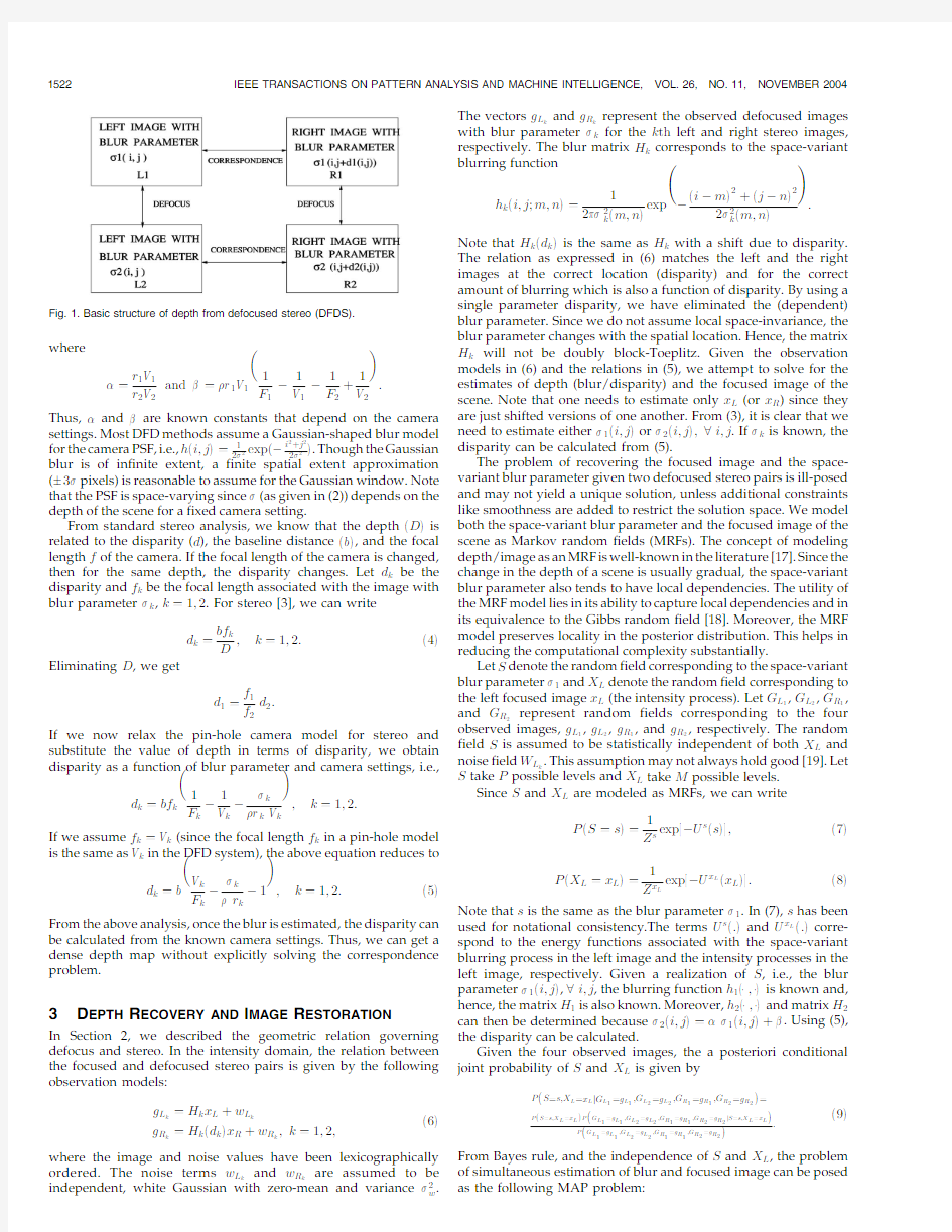
Fig.2.(a)Original focused image.(b)Left defocused image with blur 1.(c)Stereo pair of(b).(d)Left defocused image with blur 2.(e)Stereo pair of(d).(f),(g),and (h)Values of 1obtained using DFD alone,stereo alone,and the proposed method,respectively.(i)Space-variant restored image using DFDS.
Along similar lines,we have a smoothness term U sm int and a penalty term p sm int for the intensity process also and these are given as follows:
U sm int ?X i;j
x ?ex L i;j àx L i;j à1T2e1àv x L
i;j Ttex L i;j t1àx L i;j T2e1àv x L i;j t1T
tex L i;j àx L i à1;j T2e1àl x L i;j Ttex L i t1;j àx L i;j T2e1àl x L i t1;j T
and p sm int ?X
i;j
x ?l x L
i;j tl x L i t1;j tv x L i;j tv x L i;j t1 ;
e15T
where x is the regularization parameter corresponding to the
intensity image while x weights the penalty for introducing a discontinuity.Finally,the term U st data corresponds to data fitting due to stereo and is given as
U st data ? st jj g R 1àg L 1ed 1Tjj 2tjj g R 2àg L 2ed 2Tjj 2h i
;e16Twhere the parameter st weights how well the stereo image pairs
match in terms of disparity.
The posterior energy function given by (11)is nonconvex and algorithms based on steepest-descent are prone to get trapped in local minima.We choose the simulated annealing (SA)algorithm [18]for minimizing the posterior energy function so as to obtain estimates of the space-variant blur parameter and the focused image simultaneously.For this purpose,a temperature variable is introduced in the objective function.The cooling schedule was chosen to be linear.Since the random fields associated with SV blur and image are assumed to be statistically independent,the values of blur s i;j and image x i;j at every location ei;j Tare changed independently.Parameter estimation in MRF is a difficult task.Here,we choose the MRF parameters in an ad hoc way.
From (11),it may be noted that the estimates of depth and the focused image of the scene using DFD alone can be obtained by simply leaving out the stereo terms [9].However,as we shall show in the next section,the additional constraints provided by stereo are very useful in refining the estimates of depth.
4E XPERIMENTAL R ESULTS
We demonstrate the performance of the proposed method in estimating blur (or disparity or depth)and restoring the focused image.The number of discrete levels for the blur parameter was chosen to be 64.For the intensity process,256levels were used (same as the CCD dynamic range).For DFD and DFDS,the window-based method of Subbarao [7]was used to obtain initial estimates of 1.The method of Roy and Cox [20]and the implementation available at http://www2.iro.umontreal.ca/~roys/publi/iccv98/code.html was used to get the stereo estimates.
In the first experiment,defocused versions of a random dot-pattern image (Fig.2a)were generated.The blurring was stair-case type and we chose 2ei;j T?0:5 1ei;j T.Figs.2b,2c,2d,and 2e show the two defocused stereo pairs of images thus generated.Fig.2f shows the initial estimates of the blur 1using DFD alone (i.e.,without the stereo constraints).Although one can make out the stair-case nature of the blur,the estimates are not very satisfactory.The rms value of the error in the estimate of the blur was found to be 0:55.Since the blur parameter and disparity are related,estimates of the blur obtained using focused left-right stereo pairs are shown in Fig.2g.The rms value of the error is 0:38.The proposed method was next used to estimate the blur/disparity and the original focused image.The values of the various parameters used in the SA algorithm were as follows:T 0?10:0, s ?5000:0, f ?0:005, st ?0:01, s ?10:0, f ?15:0, s ?0:4, f ?25:0, s ?0:1, f ?6:0,number of annealing iterations ?200,and the number of metropolis iterations ?100.Here,T 0is the initial temperature,while s and f are thresholds for deciding the presence of an edge in the blur and in the image,respectively.The variances s 2and f 2are used in a Gaussian sampler to generate new samples of blur and intensity values and these are then used in the SA algorithm to
generate a new realization.The estimated SV blur parameter and the restored image using the proposed method are shown in Figs.2h and 2i,respectively.From the figure,it can be seen that the blur is well-captured and the edges are sharper.The improvement is particularly significant in regions of large blur where defocus is known to perform poorly due to reduced spectral content.This is also reflected in the rms error which now reduces to 0:12.Also,the restored image (which is an estimate of the original image in Fig.2a)is quite good.
The method was next tested on the corridor image (obtained from CIL/CMU database)and the defocused stereo image pairs are given in Figs.3a,3b,3c,and 3d.The defocused images were obtained from the ground-truthed disparity and depth values in conjunction with an appropriate choice of camera parameters.The true depth values are given in Fig.3e.The error in the estimates of depth using the DFD method is shown in Fig.3f.A darker gray level implies smaller error.The restored image is shown in Fig.3i.The normalized rms error for the depth map using DFD is 0:209.We note that the estimates are poor at places of large blur where there is not enough spectral content.Note that the ball is quite severely blurred and,hence,the depth estimates in that region are not good for the DFD method.Depth estimates were next obtained using focused stereo pairs of the corridor image.The error in the estimates of depth
Fig.3.(a)Left defocused image.(b)Right defocused stereo image with the same camera settings as in (a).(c)Left defocused image with different camera parameters.(d)Right defocused stereo pair with same camera settings as in (c).(e)True values of depth.(f)Error in the estimated values of depth using the DFD scheme.(g)Error in the estimated values of depth using only stereo.(h)Error in the estimated values of depth using the proposed scheme.(i)Reconstructed image using DFD alone.(j)Reconstructed image using defocus as well as stereo cues.
are displayed in Fig.3g and the normalized rms error is0:264. Results corresponding to the proposed scheme are shown in Figs.3h and3j.By fusing defocus and stereo cues,the depth estimates clearly improve.The error values are smaller compared to both DFD and stereo.We note that the estimates of depth near the cone and the ball are quite good.The rms value of the error in the estimate of depth reduces to0:149.Because the depth estimates for DFDS are better, the restored image is also cleaner with few artifacts.The ball is quite focused and emerges nicely in the restored image(Fig.3j)using DFDS as compared to DFD(Fig.3i).
Finally,the performance of the proposed scheme was tested on images captured in our laboratory.The left and right defocused stereo pairs are shown in Figs.4a,4b,4c,https://www.360docs.net/doc/5d11535874.html,ing DFD alone, the depth map and the focused image were first estimated and these are shown in Figs.4e and4g,respectively.From the figures,we note that although the recovered image is reasonably good,the depth map is not satisfactory.The estimates of depth and the focused image using the proposed scheme are given in Figs.4f and4h, respectively.The improvement due to fusion of defocus and stereo is amply evident.Some of the visible artifacts that were present in the restored image using DFD alone are now completely gone (particularly at the end nearer to the camera).The restored image is uniformly focused everywhere and is of very good quality.Also,the planar nature of the variation in the depth of the scene is better brought out by the proposed method.Since a real aperture camera cannot bring all points in a3D scene simultaneously into focus,we do not have focused image pairs of the scene for computing depth using stereo alone.A major significance of our work lies in the following fact:Due to the physics of the problem,no real aperture camera can yield the image that the proposed method has been able to produce in Fig.4h.In effect,Fig.4h is a synthesis of the focused image of the scene had the camera brought the entire3D scene into focus(this is not practically possible since a real aperture camera can only bring points at a single depth into focus).5C ONCLUSIONS
We have proposed a new method for estimating depth that combines defocus and stereo cues for images captured with a real aperture camera.The method uses ideas from both DFD and stereo to its advantage.The estimates of depth are superior compared to both DFD and stereo.The recovered depth map is dense and no feature matching or interpolation is required.The method also simultaneously restores a focused image of the scene.
A CKNOWLEDGMENTS
S.Chaudhuri gratefully acknowledges the partial support received under the Swarnajayanti Fellowship scheme.
R EFERENCES
[1] B.Julesz,“Binocular Depth Perception without Familiarity Cues,”Science,
vol.145,pp.356-362,1964.
[2] A.P.Pentland,“A New Sense for Depth of Field,IEEE Trans.Pattern
Analysis and Machine Intelligence,vol.9,pp.523-531,1987.
[3] D.Marr and T.Poggio,“Co-Operative Computation of Stereo Disparity,”
Science,vol.194,pp.283-287,1976.
[4]S.T.Barnard and W.B.Thompson,“Disparity Analysis of Images,”IEEE
Trans.Pattern Analysis and Machine Intelligence,vol.2,pp.333-339,1980. [5] D.Scharstein and R.Szeliski,“A Taxonomy and Evaluation of Dense Two-
Frame Stereo Correspondence Algorithms,”Int’l https://www.360docs.net/doc/5d11535874.html,puter Vision,vol.47, pp.7-42,2002.
[6]M.Subbarao,“Parallel Depth Recovery by Changing Camera Parameters,”
Proc.IEEE Int’l https://www.360docs.net/doc/5d11535874.html,puter Vision,pp.149-155,1988.
[7]Y.Xiong and S.A.Shafer,“Depth from Focusing and Defocusing,”Proc.
IEEE Int’l https://www.360docs.net/doc/5d11535874.html,puter Vision and Pattern Recognition,pp.68-73,1993. [8] A.N.Rajagopalan and S.Chaudhuri,“Space-Variant Approaches to
Recovery of Depth from Defocused Images,”Computer Vision and Image Understanding,vol.68,pp.309-329,1997.
[9] A.N.Rajagopalan and S.Chaudhuri,“Optimal Recovery of Depth from
Defocused Images Using an MRF Model,”Proc.IEEE Int’l https://www.360docs.net/doc/5d11535874.html,puter Vision,pp.1047-1052,1998.
[10]M.Watanabe and S.K.Nayar,“Rational Filters for Passive Depth from
Defocus,”Int’l https://www.360docs.net/doc/5d11535874.html,puter Vision,vol.27,pp.203-225,1998.
[11]Y.Y.Schechner and N.Kiryati,“Depth from Defocus vs.Stereo:How
Different Really Are They?”Int’l https://www.360docs.net/doc/5d11535874.html,puter Vision,vol.39,pp.141-162, 2000.
[12]J.Flusser and T.Suk,“Degraded Image Analysis:An Invariant Approach,”
IEEE Trans.Pattern Analysis and Machine Intelligence,vol.20,pp.590-603, 1998.
[13] A.Kubota,K.Kodama,and K.Aizawa,“Registration and Blur Estimation
Methods for Multiple Differently Focused Images,”Proc.IEEE Int’l Conf.
Image Processing,vol.2,pp.447-451,1999.
[14]J.Flusser and B.Zitova,“Combined Invariants to Linear Filtering and
Rotation,”Int’l J.Pattern Recognition and Artificial Intelligence,vol.13, pp.1123-1136,1999.
[15] F.Deschenes,P.Fuchs,and D.Zioul,“Homotopy-Based Estimation of
Depth Cues in Spatial Domain,”Proc.IEEE Int’l Conf.Pattern Recognition, vol.3,pp.627-630,2002.
[16]Y.P.Tsai,J.Leu,and C.H.Chen,“Depth Estimation by Integration of
Depth-from-Defocus and Stereo Vision,”Inst.of Information Science, Taipei,1998.
[17]J.Subrahmonia,Y.P.Hung,and D.B.Cooper,“Model-Based Segmentation
and Estimation of3D Surfaces from Two or More Intensity Images Using Markov Random Fields,”Proc.IEEE Int’l Conf.Pattern Recognition,pp.390-397,1990.
[18]S.Geman and D.Geman,“Stochastic Relaxation,Gibbs Distributions and
the Bayesian Distribution of Images,”IEEE Trans.Pattern Analysis and Machine Intelligence,vol.6,pp.721-741,1984.
[19] D.Rajan and S.Chaudhuri,“Simultaneous Estimation of Super-Resolved
Scene and depth Map from Low Resolution Observations,”IEEE Trans.
Pattern Analysis and Machine Intelligence,vol.25,pp.1102-1117,2003. [20]S.Roy and I.J.Cox,“A Maximum-Flow Formulation of the N-Camera
Stereo Correspondence Problem,”Proc.IEEE Int’l https://www.360docs.net/doc/5d11535874.html,puter Vision, pp.492-499,1998.
Fig.4.(a)Left defocused image.(b)Stereo pair of(a).(c)Left defocused image with different camera settings.(d)Stereo pair of(c).(e)Estimated values of depth using only DFD.(f)Estimated values of depth using the proposed scheme.
(g)Reconstructed image using DFD.(h)Restored focused image of the scene using the proposed method.
常用计算机术语翻译
专心翻译 做到极致 常用计算机术语翻译--本地化 软件本地化行业有很多经常使用的行业术语,非行业人士或刚刚进入该行业的新人,常常对这些术语感到困惑。另外,软件本地化行业属于信息行业,随着信息技术的迅速发展,不断产生新的术语,所以,即使有多年本地化行业经验的专业人士,也需要跟踪和学习这些新的术语。 本文列举最常用的本地化术语,其中一些也大量用在普通信息技术行业。对这些常用的术语,进行简明的解释,给出对应的英文。 加速键或快捷键(accelerate key)。常应用在Windows 应用程序中,同时按下一系列组合键,完成一个特定的功能。例如,Ctrl + P ,是打印的快捷键。 带重音的字符(accented character)。例如在拉丁字符的上面或下面,添加重音标示符号。对于汉字没有此问题。 校准(alignment)。通过比较源语言文档和翻译过的文档,创建翻译数据库的过程。使用翻译记忆工具可以半自动化地完成此过程。 双向语言(bi-directional language)。对于希伯莱语言或者阿拉伯语言,文字是从右向左显示,而其中的英文单词或商标符号从左向右显示。对于中文,都是从左向右显示。 编译版本(build)。软件开发过程中编译的用于测试的内部版本。一个大型的软件项目通常需要执行多个内部版本的测试,因此需要按计划编译出多个版本用于测试。 版本环境(build environment)。用于编译软件应用程序的一些列文件的集合。
版本健康检查(build sanity check)。由软件编译者对刚刚编译的版本快速执行基本功能检查的活动,通过检查后,再由测试者进行正规详细测试。 级连样式表(cascading style sheet -CSS)。定义html等标示文件显示样式的外部文档。 字符集(character set)。从书写系统到二进制代码集的字符映射。例如,ANSI字符集使用8位长度对单个字符编码。而Unicode,使用16位长度标示一个字符。 简体中文,日文,韩文,繁体中文(CJKT)。也可以表示为SC/JP/KO/TC或 CHS/JPN/KOR/CHT,是英文Simplified Chinese, Janpanese, Korean, Traditional Chinese的简写。 代码页(code page)。字符集和字符编码方案。对每一种语言字符,都用唯一的数字索引表示。 附属条目(collateral)。软件本地化项目中相对较小的条目。例如,快速参考卡,磁盘标签,产品包装盒,市场宣传资料等。 计算机辅助翻译(Computer Aided Translation-CAT)。计算机辅助翻译。采用计算机技术从一种自然语言到另一种语言自动或支持翻译的技术术语。 串联(Concatenation)。添加文字或字符串组成较长字符传的方式。 控制语言(Controlled language)。自然语言的子集,常用于技术文档的写作,采用更加 专心翻译做到极致
机器视觉与图像处理方法
图像处理及识别技术在机器人路径规划中的一种应用 摘要:目前,随着计算机和通讯技术的发展,在智能机器人系统中,环境感知与定位、路径规划和运动控制等功能模块趋向于分布式的解决方案。机器人路径规划问题是智能机器人研究中的重要组成部分,路径规划系统可以分为环境信息的感知与识别、路径规划以及机器人的运动控制三部分,这三部分可以并行执行,提高机器人路径规划系统的稳定性和实时性。在感知环节,视觉处理是关键。本文主要对机器人的路径规划研究基于图像识别技术,研究了图像处理及识别技术在路径规划中是如何应用的,机器人将采集到的环境地图信息发送给计算机终端,计算机对图像进行分析处理与识别,将结果反馈给机器人,并给机器人发送任务信息,机器人根据接收到的信息做出相应的操作。 关键词:图像识别;图像处理;机器人;路径规划 ABSTRACT:At present, with the development of computer and communication technology, each module, such as environment sensing, direction deciding, route planning and movement controlling moduel in the system of intelligent robot, is resolved respectively. Robot path planning is an part of intelligent robot study. The path planning system can be divided into three parts: environmental information perception and recognition, path planning and motion controlling. The three parts can be executed in parallel to improve the stability of the robot path planning system. As for environment sensing, vision Proeessing is key faetor. The robot path planning of this paper is based on image recognition technology. The image processing and recognition technology is studied in the path planning is how to apply, Robots will sent collected environment map information to the computer terminal, then computer analysis and recognize those image information. After that computer will feedback the result to the robot and send the task information. The robot will act according to the received information. Keywords: image recognition,image processing, robot,path planning
图像处理中值滤波器中英文对照外文翻译文献
中英文资料对照外文翻译 一、英文原文 A NEW CONTENT BASED MEDIAN FILTER ABSTRACT In this paper the hardware implementation of a contentbased median filter suitabl e for real-time impulse noise suppression is presented. The function of the proposed ci rcuitry is adaptive; it detects the existence of impulse noise in an image neighborhood and applies the median filter operator only when necessary. In this way, the blurring o f the imagein process is avoided and the integrity of edge and detail information is pre served. The proposed digital hardware structure is capable of processing gray-scale im ages of 8-bit resolution and is fully pipelined, whereas parallel processing is used to m inimize computational time. The architecturepresented was implemented in FPGA an d it can be used in industrial imaging applications, where fast processing is of the utm ost importance. The typical system clock frequency is 55 MHz. 1. INTRODUCTION Two applications of great importance in the area of image processing are noise filtering and image enhancement [1].These tasks are an essential part of any image pro cessor,whether the final image is utilized for visual interpretation or for automatic an alysis. The aim of noise filtering is to eliminate noise and its effects on the original im age, while corrupting the image as little as possible. To this end, nonlinear techniques (like the median and, in general, order statistics filters) have been found to provide mo re satisfactory results in comparison to linear methods. Impulse noise exists in many p ractical applications and can be generated by various sources, including a number of man made phenomena, such as unprotected switches, industrial machines and car ign ition systems. Images are often corrupted by impulse noise due to a noisy sensor or ch annel transmission errors. The most common method used for impulse noise suppressi on n forgray-scale and color images is the median filter (MF) [2].The basic drawback o f the application of the MF is the blurringof the image in process. In the general case,t he filter is applied uniformly across an image, modifying pixels that arenot contamina ted by noise. In this way, the effective elimination of impulse noise is often at the exp ense of an overalldegradation of the image and blurred or distorted features[3].In this paper an intelligent hardware structure of a content based median filter (CBMF) suita ble for impulse noise suppression is presented. The function of the proposed circuit is to detect the existence of noise in the image window and apply the corresponding MF
图像处理的流行的几种方法
一般来说,图像识别就是按照图像地外貌特征,把图像进行分类.图像识别地研究首先要考虑地当然是图像地预处理,随着小波变换地发展,其已经成为图像识别中非常重要地图像预处理方案,小波变换在信号分析识别领域得到了广泛应用. 现流行地算法主要还有有神经网络算法和霍夫变换.神经网络地方法,利用神经网络进行图像地分类,而且可以跟其他地技术相互融合.个人收集整理勿做商业用途 一神经网络算法 人工神经网络(,简写为)也简称为神经网络()或称作连接模型(),它是一种模范动物神经网络行为特征,进行分布式并行信息处理地算法数学模型.这种网络依靠系统地复杂程度,通过调整内部大量节点之间相互连接地关系,从而达到处理信息地目地.个人收集整理勿做商业用途 在神经网络理论地基础上形成了神经网络算法,其基本地原理就是利用神经网络地学习和记忆功能,让神经网络学习各个模式识别中大量地训练样本,用以记住各个模式类别中地样本特征,然后在识别待识样本时,神经网络回忆起之前记住地各个模式类别地特征并将他们逐个于样本特征比较,从而确定样本所属地模式类别.他不需要给出有关模式地经验知识和判别函数,通过自身地学习机制形成决策区域,网络地特性由拓扑结构神经元特性决定,利用状态信息对不同状态地信息逐一训练获得某种映射,但该方法过分依赖特征向量地选取.许多神经网络都可用于数字识别,如多层神经网络用于数字识别:为尽可能全面描述数字图像地特征,从很多不同地角度抽取相应地特征,如结构特征、统计特征,对单一识别网络,其输入向量地维数往往又不能过高.但如果所选取地特征去抽取向量地各分量不具备足够地代表性,将很难取得较好地识别效果.因此神经网络地设计是识别地关键.个人收集整理勿做商业用途 神经网络在图像识别地应用跟图像分割一样,可以分为两大类: 第一类是基于像素数据地神经网络算法,基于像素地神经网络算法是用高维地原始图像数据作为神经网络训练样本.目前有很多神经网络算法是基于像素进行图像分割地,神经网络,前向反馈自适应神经网络,其他还有模糊神经网络、神经网络、神经网络、细胞神经网络等.个人收集整理勿做商业用途 第二类是基于特征数据地神经网络算法.此类算法中,神经网络是作为特征聚类器,有很多神经网络被研究人员运用,如神经网络、模糊神经网络、神经网络、自适应神经网络、细胞神经网络和神经网络.个人收集整理勿做商业用途 例如神经网络地方法在人脸识别上比其他类别地方法有独到地优势,它具有自学习、自适应能力,特别是它地自学能力在模式识别方面表现尤为突出.神经网络方法可以通过学习地过程来获得其他方法难以实现地关于人脸识别规律和规则地隐性表达.但该方法可能存在训练时间长、收敛速度慢地缺点.个人收集整理勿做商业用途 二小波变换 小波理论兴起于上世纪年代中期,并迅速发展成为数学、物理、天文、生物多个学科地重要分析工具之一;其具有良好地时、频局域分析能力,对一维有界变差函数类地“最优”逼近性能,多分辨分析概念地引入以及快速算法地存在,是小波理论迅猛发展地重要原因.小波分析地巨大成功尤其表现在信号处理、图像压缩等应用领域.小波变换是一种非常优秀地、具有较强时、频局部分析功能地非平稳信号分析方法,近年来已在应用数序和信号处理有很大地发展,并取得了较好地应用效果.在频域里提取信号里地相关信息,通过伸缩和平移算法,对信号进行多尺度分类和分析,达到高频处时间细分、低频处频率细分、适应时频信号分解地要求.小波变换在图像识别地应用,包括图形去噪、图像增强、图像融合、图像压缩、图像分解和图像边缘检测等.小波变换在生物特征识别方面(例如掌纹特征提取和识别)同样得到了成功应用,部分研究结果表明在生物特征识别方面效果优于、、傅里叶变换等方
实验一图像处理基本操作
实验一图像处理基本操作 一、 实验目的 1、熟悉并掌握在MATLAB中进行图像类型转换及图像处理的基本操作。 2、熟练掌握图像处理中的常用数学变换。 二、实验设备 1、计算机1台 2、MATLAB软件1套 3、实验图片 三、实验原理 1、数字图像的表示和类别 一幅图像可以被定义为一个二维函数f(x,y),其中x和y是空间(平面)坐标,f在坐标(x,y)处的幅度称为图像在该点的亮度。灰度是用来表示黑白图像亮度的一个术语,而彩色图像是由若干个二维图像组合形成的。例如,在RGB彩色系统中,一幅彩色图像是由三幅独立的分量图像(红、绿、蓝)组成的。因此,许多为黑白图像处理开发的技术也适用于彩色图像处理,方法是分别处理三幅独立的分量图像即可。 图像关于x和y坐标以及幅度连续。要将这样的一幅图像转化为数字形式,就要求数字化坐标和幅度。将坐标值数字化称为取样,将幅度数字化称为量化。采样和量化的过程如图1所示。因此,当f的x、y分量和幅度都是有限且离散的量时,称该图像为数字图像。 作为MATLAB基本数据类型的数组十分适于表达图像,矩阵的元素和图像的像素之间有着十分自然的对应关系。 图1 图像的采样和量化 图1 采样和量化的过程 根据图像数据矩阵解释方法的不同,MATLAB把其处理为4类: ?亮度图像(Intensity images) ?二值图像(Binary images) ?索引图像(Indexed images) ? RGB图像(RGB images) (1) 亮度图像 一幅亮度图像是一个数据矩阵,其归一化的取值表示亮度。若亮度图像的像素都是uint8类型或uint16类型,则它们的整数值范围分别是[0,255]和[0,65536]。若图像是double 类型,则像素取值就是浮点数。规定双精度double型归一化亮度图像的取值范围是[0 1]。 (2) 二值图像 一幅二值图像是一个取值只有0和1的逻辑数组。而一幅取值只包含0和1的uint8
图像处理外文翻译 (2)
附录一英文原文 Illustrator software and Photoshop software difference Photoshop and Illustrator is by Adobe product of our company, but as everyone more familiar Photoshop software, set scanning images, editing modification, image production, advertising creative, image input and output in one of the image processing software, favored by the vast number of graphic design personnel and computer art lovers alike. Photoshop expertise in image processing, and not graphics creation. Its application field, also very extensive, images, graphics, text, video, publishing various aspects have involved. Look from the function, Photoshop can be divided into image editing, image synthesis, school tonal color and special effects production parts. Image editing is image processing based on the image, can do all kinds of transform such as amplifier, reducing, rotation, lean, mirror, clairvoyant, etc. Also can copy, remove stain, repair damaged image, to modify etc. This in wedding photography, portrait processing production is very useful, and remove the part of the portrait, not satisfied with beautification processing, get let a person very satisfactory results. Image synthesis is will a few image through layer operation, tools application of intact, transmit definite synthesis of meaning images, which is a sure way of fine arts design. Photoshop provide drawing tools let foreign image and creative good fusion, the synthesis of possible make the image is perfect. School colour in photoshop with power is one of the functions of deep, the image can be quickly on the color rendition, color slants adjustment and correction, also can be in different colors to switch to meet in different areas such as web image design, printing and multimedia application. Special effects production in photoshop mainly by filter, passage of comprehensive application tools and finish. Including image effects of creative and special effects words such as paintings, making relief, gypsum paintings, drawings, etc commonly used traditional arts skills can be completed by photoshop effects. And all sorts of effects of production are
工具软件 翻译软件概述
工具软件翻译软件概述 翻译软件的产生是随计算机技术的进步而产生的一种应用软件。早期的翻译软件功能较弱,只能根据固定的词汇或词组进行翻译,仅相当于电子版本的词典。人工智能技术的发展为翻译软件提供了极大的技术支持。现代的翻译软件已经能够识别各种自然语言的简单语法,并根据一定的语义环境进行智能翻译。 1.翻译软件分类 根据翻译软件的功能,可以将翻译软件分为词典软件、屏幕翻译软件以及辅助翻译软件等三大类。 ●词典软件 词典软件是类似实体书词典的软件。其功能是将各种语言的词汇翻译存储到数据库中,供用户调用。当用户输入某个词汇后,即可将该词汇翻译为另一种语言,如图4-1所示。 图4-1 词典软件的原理 由于计算机存储数据和查找数据非常便捷,因此,词典软件的出现,免去了用户在实体书词典中翻找的不便,提高了用户查找词汇的效率。国内常用的词典软件包括金山词霸、东方大典等。 ●屏幕翻译软件 词典软件要翻译的主要是各种词汇和短语等,而屏幕翻译软件则需要对各种语句、段落甚至文章进行翻译。相对词典软件而言,屏幕翻译软件更加智能化,功能也更加强大。屏幕翻译软件的工作原理如图4-2所示。 图4-2 屏幕翻译软件的工作原理 屏幕翻译软件往往可以根据要翻译的内容词汇,自主选择相应的词典,然后根据词典的语义进行智能翻译。虽然屏幕翻译软件可以翻译一些简单的句子和段落,但仍然无法取代人工翻译。仅能在少数领域作为人工翻译的补充而存在。目前国内常用的屏幕翻译软件主要包括金山快译、灵格斯词霸等。 ●辅助翻译软件 辅助翻译软件是辅助人工翻译的软件。其作用是以数据库的方式储存原文和译文,在翻译时以电脑分析与搜寻翻译记忆库,找出相同或类似的句子,共译者参考。使用辅助翻译软
实训三图像频域处理基本操作
实训三:图像频域处理基本操作 一:实验的目的 1:掌握基本的离散傅里叶变换操作,熟悉命令fftn, fftshift,ifftn。 2:对图像text.png进行图像特征识别操作。 二:实验指导: 1.通过MATLAB的Help文档,学习Image Processing Toolbox中关于图像变换的内容。 2.通过MATLAB的Help文档,查询命令fftn, fftshift,ifftn的用法。 3. 用MATLAB生成一个矩形连续函数并得到它的傅里叶变换的频谱。
4.对图像text.png中的字母a完成特征识别操作。
一 bw = imread('text.png'); a = bw(32:45,88:98); imview(bw); imshow(bw); figure, imshow(a); C = real(ifft2(fft2(bw) .* fft2(rot90(a,2),256,256))); figure, imshow(C,[]) max(C(:)) thresh = 60; figure, imshow(C > thresh) ans = 68
N=100 f=zeros(500,500); f(60:180,30:400)=1; subplot(221),imshow(f) subplot(221),imshow(f,'notruesize') F1=fft2(f,N,N),
F1=fft2(f,N,N), F2=fftshift(abs(F1)); F3=abs(log(1+F2)); subplot(222), imshow(F3,[]) imshow(F3,[]); f1=imrotate(f,45,'bicubic') subplot(223),imshow(f1); F21=fft2(f1,N,N); F22=abs((log(1+F22)); F22=abs((log(1+F21))); F23=abs(log(1+F22)); subplot(224), imshow(F23,[])
(完整版)导数与函数图像问题
导数与函数图像问题 1.函数()y f x =的图像如右图,那么导函数,()y f x =的图像可能是( ) 2.函数)(x f 的定义域为开区间),(b a ,导函数)(x f ' 在),(b a 内的图象如图所示,则函数)(x f 在开区间),(b a 内有极小值点( ) A. 1个 B.2个 C.3个 D.4个 3.设()f x '是函数()f x 的导函数,将()y f x =和 ()y f x '=的图象画在同一个直角坐标系中,不可能正确的是( ) 4若函数f (x )=x 2+bx+c 的图象的顶点在第四象限,则函数f′(x )的图象是( ) A . B . C . D . 5.设函数f (x )在R 上可导,其导函数为f′(x ),且函数f (x )在x=-2处取得极小值,则函数y=xf′(x )的图象可能是( ) A . B . C . D . a b x y ) (x f y ?=O
6.设函数f(x)=ax2+bx+c(a,b,c∈R),若x=-1为函数y=f(x)e x的一个极值点,则下列图象不可能为y=f(x)的图象是() A.B.C.D. 7.若函数y=f(x)的导函数在区间[a,b]上是增函数,则函数y=f(x)在区间[a,b]上的图象可能是() A.B.C.D. 8.已知函数y=xf′(x)的图象如上中图所示(其中f′(x)是函数f(x)的导函数),下面四个图象中y=f(x)的图象大致是() A.B.C.D. 9.设函数f(x)在R上可导,其导函数为f′(x),且函数y=(1-x)f′(x)的图象如上右图所示,则下列结论中一定成立的是()
图像处理中常用英文词解释
Algebraic operation 代数运算一种图像处理运算,包括两幅图像对应像素的和、差、积、商。 Aliasing 走样(混叠)当图像像素间距和图像细节相比太大时产生的一种人工痕迹。Arc 弧图的一部分;表示一曲线一段的相连的像素集合。 Binary image 二值图像只有两级灰度的数字图像(通常为0和1,黑和白) Blur 模糊由于散焦、低通滤波、摄像机运动等引起的图像清晰度的下降。 Border 边框一副图像的首、末行或列。 Boundary chain code 边界链码定义一个物体边界的方向序列。 Boundary pixel 边界像素至少和一个背景像素相邻接的内部像素(比较:外部像素、内部像素) Boundary tracking 边界跟踪一种图像分割技术,通过沿弧从一个像素顺序探索到下一个像素将弧检测出。 Brightness 亮度和图像一个点相关的值,表示从该点的物体发射或放射的光的量。 Change detection 变化检测通过相减等操作将两幅匹准图像的像素加以比较从而检测出其中物体差别的技术。 Class 类见模或类 Closed curve 封闭曲线一条首尾点处于同一位置的曲线。 Cluster 聚类、集群在空间(如在特征空间)中位置接近的点的集合。 Cluster analysis 聚类分析在空间中对聚类的检测,度量和描述。 Concave 凹的物体是凹的是指至少存在两个物体内部的点,其连线不能完全包含在物体内部(反义词为凸) Connected 连通的 Contour encoding 轮廓编码对具有均匀灰度的区域,只将其边界进行编码的一种图像压缩技术。 Contrast 对比度物体平均亮度(或灰度)与其周围背景的差别程度 Contrast stretch 对比度扩展一种线性的灰度变换 Convex 凸的物体是凸的是指连接物体内部任意两点的直线均落在物体内部。Convolution 卷积一种将两个函数组合成第三个函数的运算,卷积刻画了线性移不变系统的运算。 Corrvolution kernel 卷积核1,用于数字图像卷积滤波的二维数字阵列,2,与图像或信号卷积的函数。 Curve 曲线1,空间的一条连续路径,2 表示一路径的像素集合(见弧、封闭曲线)。 Deblurring 去模糊1一种降低图像模糊,锐化图像细节的运算。2 消除或降低图像的模糊,通常是图像复原或重构的一个步骤。 Decision rule 决策规则在模式识别中,用以将图像中物体赋以一定量的规则或算法,这种赋值是以对物体特征度量为基础的。 Digital image 数字图像 1 表示景物图像的整数阵列,2 一个二维或更高维的采样并量化的函数,它由相同维数的连续图像产生,3 在矩形(或其他)网络上采样一连续函数,并才采样点上将值量化后的阵列。 Digital image processing 数字图像处理对图像的数字化处理;由计算机对图片信息进
图像处理方法
i=imread('D:\00001.jpg'); >> j=rgb2gray(i); >> warning off >> imshow(j); >> u=edge(j,'roberts'); >> v=edge(j,'sobel'); >> w=edge(j,'canny'); >> x=edge(j,'prewitt'); >> y=edge(j,'log'); >> h=fspecial('gaussian',5); >> z=edge(j,'zerocross',[],h); >> subplot(2,4,1),imshow(j) >> subplot(2,4,2),imshow(u) >> subplot(2,4,3),imshow(v) >> subplot(2,4,4),imshow(w) >> subplot(2,4,5),imshow(x) >> subplot(2,4,6),imshow(y) >> subplot(2,4,7),imshow(z)
>> %phi:地理纬度lambda:地理经度delta:赤纬omega:时角lx 影子长,ly 杆长 >> data=xlsread('D:\附件1-3.xls','附件1'); >> X = data(:,2); >> Y = data(:,3); >> [x,y]=meshgrid(X,Y); %生成计算网格 >> fxy = sqrt(x.^2+y.^2); >> %[Dx,Dy] = gradient(fxy); >> Dx = x./fxy; >> Dy = y./fxy; >> quiver(X,Y,Dx,Dy); %用矢量绘图函数绘出梯度矢量大小分布>> hold on >> contour(X,Y,fxy); %与梯度值对应,绘出原函数的等值线图
envi图像处理基本操作
使用ENVI进行图像处理 主要介绍利用envi进行图像处理的基本操作,主要分为图像合成、图像裁减、图像校正、图像镶嵌、图像融合、图像增强。 分辨率:空间分辨率、波谱分辨率、时间分辨率、辐射分辨率。咱们平时所说的分辨率是指?怎么理解? 1、图像合成 对于多光谱影像,当我们要得到彩色影像时,需要进行图像合成,产生一个与自然界颜色一致的真彩色(假彩色)图像。 对于不同类型的影像需要不同的波段进行合成,如中巴CCD影像共5个波段,一般选择2、4、3进行合成。(为什么不选择其他波段?重影/不是真彩色)。SOPT5影像共7个波段,一般选择7、4、3三个波段。 操作过程以中巴资源卫星影像为例 中巴资源卫星影像共有五个波段,选择2、4、3三个波段对R、G、B赋值进行赋值。 在ENVI中的操作如下: (1)file→open image file→打开2、3、4三个波段,选择RGB,分别将2、4、3赋予RGB。(2)在#1窗口file---〉save image as-→image file。 (3)在主菜单中将合成的文件存为tiff格式(file-→save file as-→tiff/geotiff) 即可得到我们需要的彩色图像。 2、图像裁减 有时如果处理较大的图像比较困难,需要我们进行裁减,以方便处理。如在上海出差时使用的P6、SOPT5,图幅太大不能直接校正需要裁减。 裁减图像,首先制作AOI文件再根据AOI进行裁减。一般分为两种:指定范围裁减、不指定范围裁减。 不指定范围裁减在ENVI中的操作如下: (1)首先将感兴趣区存为AOI文件 file→open image file打开原图像→选择IMAGE窗口菜单overlay→region of interesting 选择划定感兴趣区的窗口如scroll,从ROI_Type菜单选择ROI的类型如Rectangle,在窗口中选出需要选择的区域。在ROI窗口file→Save ROIs将感兴趣区存为ROI文件。
导数与函数图像
导数与函数图像问题
1.函数 y ? f (x) 的图像如右图,那么导函数 y ? f , (x) 的图像可能是( )
2.函数 f (x) 的定义域为开区间 (a, b) ,导函数 f ?(x) 在 (a, b) 内的图象如图所示,则函数 f (x) 在开区间 (a, b)
内有极小值点( )
A. 1个 B. 2 个 C. 3 个 D. 4 个
a
3 . 设 f ?(x) 是 函 数 f (x) 的 导 函 数 , 将 y ? f (x) 和
y
y ? f ?(x)
b
O
x
y ? f ?(x) 的图象画在同一个直角坐标系中,不可能正确的是( )
4若 函 数 f( x) =x2+bx+c 的 图 象 的 顶 点 在 第 四 象 限 , 则 函 数 f′ ( x) 的 图 象 是 (
)
A.
B.
C.
D.
5.设 函 数 f( x) 在 R 上 可 导 , 其 导 函 数 为 f′ ( x), 且 函 数 f( x) 在 x=-2处 取 得 极 小 值,则函数 y=xf′(x)的图象可能是( )
A.
B.
C.
D.
1
6. 设 函 数 f( x) =ax2+bx+c( a, b, c∈ R), 若 x=-1为 函 数 y=f( x) ex 的 一 个 极 值 点 , 则下列图象不可能为 y=f(x)的图象是( )
A.
B.
C.
D.
7.若函数 y=f(x)的导函数在区间[a,b]上是增函数,则函数 y=f(x)在区间[a,b] 上的图象可能是( )
A.
B.
C.
D.
8.已 知 函 数 y=xf′( x)的 图 象 如 上 中 图 所 示( 其 中 f′( x)是 函 数 f( x)的 导 函 数 ),
下面四个图象中 y=f(x)的图象大致是( )
A.
B.
C.
D.
9.设函数 f(x)在 R 上可导,其导函数为 f′(x),且函数 y=(1-x)f′(x)的图象如上
右图所示,则下列结论中一定成立的是( )
A.函数 f(x)有极大值 f(2)和极小值 f(1) 值 f(1) C.函数 f(x)有极大值 f(2)和极小值 f(-2) 值 f(2)
B.函数 f(x)有极大值 f(-2)和极小 D.函数 f(x)有极大值 f(-2)和极小
2
常用工具软件试题库
《常用工具软件》考试题库 一.判断题(每小题1分,共10分) 1. Realone Player不支持多节目连续播放。(X) 2.网际快车可以上传和下载文件。(√) 3. Internet上所有电子邮件用户的E-mail地址都采用同样的格式:用户名@主机名。(√) 4.Adobe Acrobat Reader可以解压缩文件。(X) 5.ACDSee是目前最流行的数字图像处理软件,它能广泛应用于图片的获取、管理、浏览、优化,甚至和他人的分享。(√) 6.天网防火墙的拦截功能是指数据包无法进入或出去。(X) 7.Symantec Ghost可以实现数据修复。(X) 8. 用户可以向金山词霸词库中添加没有收录的中、英文单词。(√) 9.系统长时间使用之后,会留下一堆堆垃圾文件,使系统变得相当臃肿,运行速度大为下降,但是系统不会频繁出错甚至死机。(√) 10.在使用FlashFXP软件下载网络中的FTP资源时,只需掌握FTP服务器的URL地址即可。(√) 11.在安装瑞星防火墙时,旧版本的瑞星防火墙无需卸载。(X) 12.压缩文件管理工具WinRAR只能压缩文件,不能对文件进行解压。(X) 13.在使用Virtual CD时,映像文件是不能被Windows资源管理器直接读取的,必须从Virtual CD中提取。(√) 14.在用Nero - Burning Rom软件制作CD时,可将数据文件从本地资源管理器中拖入了刻录机虚拟资源管理器中。(X) 15. 超级解霸3000能截取当前视频窗口中的图像存为图形文件。(√) 16.用MSN聊天时,可以隐身登录。(√) 17.ACDSee是目前最流行的数字图像处理软件,它能广泛应用于图片的获取、管理、浏览、优化,甚至和他人的分享。(√) 18、病毒不属于计算机软件(×) 19、优化大师就是让系统运行后没有垃圾文件(×) 20、注册表直接影响系统运行的稳定性(√) 21、清理注册表就是删除注册表中无用软件的注册信息(×) 22、360杀毒不能对单个文件进行病毒查杀(×) 23、根据工具软件使用的领域不同,但是一般都包含有标题栏、菜单栏、工具栏、状态栏、工作区。(√) 24、在进行实验操作时,为了不破坏现有的操作系统以及相关设置,我们可以使用虚拟机软件。(√) 25、在使用虚拟机的时候,按键盘右边的ALT可以在虚拟机和宿主机之间切换。(√) 26、CuteFTP是一个基于文件传输协议客户端软件。(√) 27、虚拟光驱是一种模拟CD-ROM工作的工具软件,它能在操作系统中模拟出新的光盘驱动器,是对物理光驱的一种仿真。(√) 28、利用ghost可以备份windows操作系统。(√) 29、常见的压缩格式ZIP格式、RAR格式、CBA格式、ACE格式。(√) 30、利用CuteFTP软件可以上传网站文件。(√) 31、Deamon Tools是一个优秀的虚拟光驱工具。(√)
图像处理基本方法
图像处理的基本步骤 针对不同的目的,图像处理的方法不经相同。大体包括图像预处理和图像识别两大模块。 一、图像预处理: 结合识别复杂环境下的成熟黄瓜进行阐述,具体步骤如下: · 图像预处理阶段的流程图 对以上的图像流程进行详细的补充说明: 图像预处理的概念: 将每一个文字图像分检出来交给识别模块识别,这一过程称为图像预处理。 图像装换和图像分割以及区域形态学处理都是属于图像处理的基本内容之一。 图像转换:方法:对原图像进行灰度化处理生成灰度矩阵——降低运算速度(有具体的公式和方程),中值滤波去噪声——去除色彩和光照的影响等等。 图像分割:传统方法:基于阈值分割、基于梯度分割、基于边缘检测分割和基于区域图像割等方法。脉冲耦合神经网络 (PCNN)是针对复杂环境下 图像采集 图像采集中注意采集的方法、工具进行介绍。目的是怎样获取有代表性的样本。(包括天气、相机的位置等) 对采集的图像进行特征分析 目标的颜色和周围环境的颜色是否存在干涉的问题、平整度影响相机的拍摄效果、形状 图像转换 图像分割 区域形态学处理
的有效分割方法,分割的时候如果将一个数字图像输入PCNN,则能基于空间邻近性和亮度相似性将图像像素分组,在基于窗口的图像处理应用中具有很好的性能。 区域形态学处理:对PCNN分割结果后还存在噪声的情况下,对剩余的噪声进行分析,归类属于哪一种噪声。是孤立噪声还是黏连噪声。采用区域面积统计法可以消除孤立噪声。对于黏连噪声,可以采用先腐蚀切断黏连部分,再膨胀复原目标对象,在进行面积阙值去噪,通过前景空洞填充目标,最后通过形态学运算,二值图像形成众多独立的区域,进行各连通区域标识,利于区域几何特征的提取。 二、图像识别: 针对预处理图像提取 目标特征 建立LS SVM分类器 得到结果 图像识别流程图 提取目标特征:目标特征就是的研究对象的典型特点,可以包括几何特征和纹理特征。 对于几何特征采用的方法:采用LS-SVM支持向量机对几何特征参数进行处理,通过分析各个参数的分布区间来将目标和周围背景区分开,找出其中具有能区分功能的决定性的几何特征参数。 纹理特征方法:纹理特征中的几个参数可以作为最小二乘支持向量机的辅助特征参数,提高模型的精准度。 最小二乘支持向量机介绍:首先选择非线性映射将样本从原空间映射到特征空间,以解决原空间中线性不可分问题,在此高维空间中把最优决策问题转化为等式约束条件,构造最优决策函数,并引入拉格朗日乘子求解最优化问题,对各个变量求偏微分。 LS SVM分类器:对于p种特征选择q个图像连通区域,作为训练样本。依