美制外螺纹常用规格尺寸表
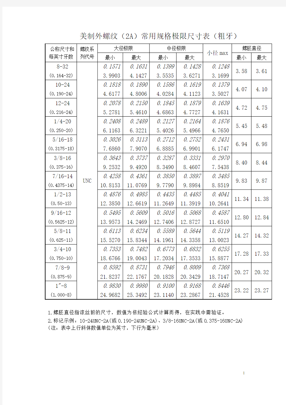

1.螺胚直径指滚丝前的尺寸,数值为依经验公式计算而得,在实践中需验证。
2.标记示例:10-24UNC-2A(或0.190-24UNC-2A)、3/8-16UNC-2A(或0.375-16UNC-2A) (注:表中上行斜体数值单位为英寸,下行为毫米)
1.螺胚直径指滚丝前的尺寸,数值为依经验公式计算而得,在实践中需验证。
2.标记示例:10-32UNF-2A(或0.190-32UNF-2A)、3/8-24UNF-2A(或0.375-24UNF-2A)
1.底孔直径指攻丝前钻孔直径,铸铁、黄铜等较软料取小值,钢、青铜等较硬料取大值。
2.标记示例:10-24UNC-2B(或0.190-24UNC-2B)、3/8-16UNC-2B(或0.375-16UNC-2B)
1.底孔直径指攻丝前钻孔直径,铸铁、黄铜等较软料取小值,钢、青铜等较硬料取大值。
2.标记示例:10-32UNF-2B(或0.190-32UNF-2B)、3/8-24UNF-2B(或0.375-24UNF-2B)
英制管螺纹美制管螺纹对照表
分类:专业知识 字号:大中小 英制管螺纹美制管螺纹对照表 英制管螺纹英制管螺纹美制管螺纹 规格标准径钻孔径 规格 标准径有交牙 部之长度(最 小)中之毋螺 牙内径 标准长 度(最小)中 之毋螺牙内径 规格 钻孔径 最大最小使用纹刀时 不用纹刀 时 NPT NPS 使用绞刀时不用绞刀时 PS 1/16-28 6.50 6.632 6.490 PT 1/16-28 6.10 6.20 6.244 6.384 1/16 - 27 6.10 6.25 6.35 PS 1/8-28 8.50 8.637 8.495 PT 1/8-28 8.10 8.20 8.249 8.388 1/8 - 27 8.33 8.43 8.74 PS 1/4-19 11.40 11.549 11.341 P T 1/4-19 10.70 11.0 10.962 11.174 1/4 - 18 10.72 11.13 11.13 PS 3/8-19 15.00 15.054 14.846 P T 3/8-19 14.20 14.5 14.448 14.658 3/8 - 18 14.27 14.27 14.68 PS 1/2-14 18.50 18.773 18.489 P T 1/2-14 17.60 18.0 17.979 18.263 1/2 - 14 17.48 17.86 18.26 PS 3/4-14 24.00 24.259 23.975 P T 3/4-14 23.00 23.5 23.378 23.663 3/4 - 14 22.63 23.01 23.42 PS 1-11 30.20 30.471 30.111 P T 1-11 29.00 29.5 29.459 29.822 1 - 11-1/2 28.58 28.98 29.36
螺纹基本尺寸对照表要点
英制管螺纹基本尺寸及公差(牙形角55o)BSPP 英制锥管螺纹基本尺寸及公差(牙形角55o)BSPT
美制管螺纹基本尺寸及公差(牙形角60o)UN(F)
公制螺纹基本尺寸及公差(牙形角60o) M
55°圆锥管螺纹基本尺寸对照表最新下载-汇兴达55°圆锥管螺纹基本尺寸对照表最新下载-汇兴达55°圆锥管螺纹(BSPT)
聊城市鑫茂祥管业有限公司专业经营钢管规格:5mm*1mm—1020mm*200mm合金钢管、外径22mm-127mm 冷轧无缝钢管、外径127mm-600mm,壁厚16mm-100mm,外径精度±0.5%,壁厚精度±5%热轧中厚壁无缝钢管、16Mn外径400—1600mm、壁厚20—60mm的大口径厚壁卷管,可定尺到16米及各种规格的无缝方管、异型无缝钢管等.常备钢管种类有:构造用无缝钢管、流体用无缝钢管、液压无缝钢管、电力用无缝钢管、石油输送用无缝钢管、化肥设备用无缝钢管、煤矿用无缝钢管、不锈钢无缝钢管、化工用无缝钢管、纺织机械用无缝钢管、汽车;水利用无缝钢管,精密无缝钢管、光亮无缝钢管、军工医疗用无缝钢管、管道用无缝钢管、支柱用无缝钢管、合金无缝管、高压无缝管、大口径直缝焊管等。适用于工程、煤矿、纺织、电力、锅炉、机械、军工等各个领域。公司以良好的信用、优质的产品、雄厚的实力、低廉的价钱享誉全国30多个省、市、自治区、直辖市及国外,产品深得用户依赖。 公司常年销售成都钢铁集团、冶钢集团、包头钢厂、宝钢集团、鞍钢集团、天津大无缝、西宁特钢厂、无锡钢厂、衡阳钢厂等各大钢厂生产的各种无缝钢管及合金管。主营材质:20#、35#、45#、20G、20A、40Mn2、45Mn2、27SiMn、
美制螺纹对照表
美制螺纹尺寸表单位:mm 外螺纹内螺纹公称 螺纹牙牙螺公差螺纹外径螺纹中径螺纹小径公差螺纹小径螺纹中径螺纹外径钻孔直径规格数高距代号Max Min Max Min Max代号Min Max Min Max Min直径 0.073(#1)1-64UNC640.2360.3972A 1.83896 1.74244 1.58242 1.53162 1.366522B 1.42494 1.58242 1.59766 1.6637 1.8542 1.397 1.8543A 1.8542 1.75768 1.59766 1.55956 1.381763B 1.42494 1.58242 1.59766 1.64592 1.8542 1.397 1-72UNF720.210.3532A 1.83896 1.75006 1.61036 1.5621 1.419862B 1.4732 1.6129 1.6256 1.6891 1.8542 1.5113 3A 1.8542 1.7653 1.6256 1.59004 1.43513B 1.4732 1.6129 1.6256 1.67386 1.8542 1.5113 0.086(#2)2-56UNC560.2710.4542A 2.16916 2.06502 1.87452 1.82118 1.630682B 1.69418 1.87198 1.88976 1.96088 2.1844 1.7018 2.1843A 2.1844 2.08026 1.88976 1.84912 1.645923B 1.69418 1.87198 1.88976 1.9431 2.1844 1.7018 2-64UNF640.2360.3972A 2.16916 2.07264 1.91262 1.86182 1.696722B 1.75514 1.91262 1.92786 1.99644 2.1844 1.778 3A 2.1844 2.08788 1.92786 1.88976 1.711963B 1.75514 1.91262 1.92786 1.97866 2.1844 1.778 0.099(3#))3-48UNC480.3150.5292A 2.49682 2.38252 2.15392 2.0955 1.864362B 1.94056 2.1463 2.1717 2.2479 2.5146 1.9939 2.5153A 2.5146 2.4003 2.1717 2.12852 1.882143B 1.94056 2.1463 2.1717 2.22758 2.5146 1.9939 3-56UNF560.2710.4542A 2.49682 2.39268 2.20218 2.1463 1.958342B 2.02438 2.1971 2.21996 2.29108 2.5146 2.0574 3A 2.5146 2.41046 2.21996 2.17932 1.976123B 2.02438 2.1971 2.21996 2.2733 2.5146 2.0574 0.112(#4)4-40UNC400.3780.6352A 2.82448 2.69494 2.413 2.3495 2.067562B 2.15646 2.38506 2.43332 2.51714 2.8448 2.1844 2.8453A 2.8448 2.71526 2.43332 2.38506 2.087883B 2.15646 2.38506 2.43332 2.49428 2.8448 2.1844 4-48UNF480.3150.5292A 2.82702 2.71272 2.48412 2.42316 2.194562B 2.27076 2.45872 2.5019 2.58064 2.8448 2.2606 3A 2.8448 2.7305 2.5019 2.45618 2.212343B 2.27076 2.45872 2.5019 2.56032 2.8448 2.2606 0.125(#5)5-40UNC400.3780.6352A 3.15468 3.02514 2.7432 2.67716 2.397762B 2.48666 2.69748 2.76352 2.84734 3.175 2.5273 3.1753A 3.175 3.04546 2.76352 2.71526 2.418083B 2.48666 2.69748 2.76352 2.82702 3.175 2.5273 5-44UNF440.3440.5772A 3.15722 3.0353 2.7813 2.7178 2.468882B 2.55016 2.74066 2.79908 2.88036 3.175 2.5781 3A 3.175 3.05308 2.79908 2.75082 2.486663B 2.55016 2.74066 2.54508 2.86004 3.175 2.5781 0.138(#6)6-32UNC320.4720.7942A 3.48488 3.33248 2.96926 2.89814 2.542B 2.6416 2.8956 2.98958 3.08356 3.5052 2.7051 3.5053A 3.5052 3.3528 2.98958 2.93624 2.560323B 2.6416 2.8956 2.98958 3.05816 3.5052 2.7051 6-40UNF400.3780.6352A 3.48488 3.35534 3.0734 3.00736 2.727962B 2.8194 3.0226 3.09372 3.18008 3.5052 2.8702 3A 3.5052 3.37566 3.09372 3.04292 2.748283B 2.8194 3.01244 3.09372 3.15722 3.5052 2.8702 0.164(#8)8-32UNC320.4720.7842A 4.14274 3.99034 3.62712 3.55346 3.197862B 3.302 3.5306 3.64998 3.7465 4.1656 3.4544
英、美制螺纹标准直径、螺距参照表
英、美制标准螺纹直径、螺距参照系列表 UNC-粗牙UNF-细牙 标准国别美制ANSI BI.1-1982英国标准BS84-1956 规格直径UNC牙数/寸UNF牙数/寸BSW牙数/寸BSF牙数/寸0# 1.52 / 80 / / 1# 1.85 64 72 / / 2# 2.18 56 64 / / 3# 2.51 48 56 / / 4# 2.84 40 48 / / 5#,(1/8”) 3.18 40 44 40 / 6# 3.51 32 40 / / 8# 4.17 32 36 / / 10#(3/16”) 4.83 24 32 24 32 12#(7/32”) 5.49 24 28 / 28 1/4” 6.35 20 28 20 26 5/16”7.94 18 24 18 22 3/8”9.53 16 20 16 20 7/16”11.11 14 20 14 18 1/2”12.70 13 18 12 16 9/16”14.29 12 18 12 16 5/8”15.88 11 / 11 14 11/16”17.46 / 16 11 14 3/4”19.05 10 / 10 12 13/16”20.64 / 14 / / 7/8”22.23 9 / 9 11 15/16”23.81 / 12 / / 1”25.40 8 12 8 10 1 1/8”28.58 7 1 2 7 9
1 1/4”31.75 7 1 2 7 9 1 3/8”34.93 6 1 2 / 8 1 1/2" 38.10 6 1 2 6 8 1 5/8”41.28 / / / 8 1 3/4”44.45 5 / 5 7 1 7/8”47.63 / / / 2”50.80 4.5 / 5 7 螺纹站孔的直径的计算 一般按下列公式: 1.攻公制螺纹:螺距t<1毫米,dz=d-t t>1毫米,dz=d-(1.04~1.06)t 式中t——螺距(毫米) dz——攻丝前钻孔直径(毫米) d——螺纹公称直径(毫米) 2.攻英制螺纹: 螺纹公称直径铸铁与青铜钢与黄铜 3/16"~5/8" dz=25(d-1/n) dz=25(d-1/n)+0.1 3/4"~11/2" dz=25(d-1/n) dz=25(d-1/n) +0.2 式中dz——攻丝前钻孔直径(毫米) d——螺纹公称直径(英寸)n——每英寸牙数
公制,英制,美制螺纹尺寸对照表
螺纹简介:
1.1螺纹的起源 一般认为,阿基米德(公元前287-212年)是首先将螺纹用于工业目的,即将低处的水移到高处的一种工具。1659年法国人贝兹逊发明螺纹切割机;其后,经过英国的威阿特、亨利?莫斯列,到其子弟约瑟夫?惠氏于1841年才统一原本混乱的螺纹,促进螺纹制品的全球普及;因此,惠氏螺纹也随英国工业的发达而广泛传播世界。 美制螺纹依据塞勒氏螺纹(Seller's thread)而问世于1924年;二次世界大战中,美国、英国、加拿大三国协定发展成统一制螺纹Unified thread。随着国际交流的频繁,1947年成立的ISO国际标准化组织(International standard organization)成为推动国际标准化的重要力量。 1.2螺纹概述 按用途分类,可分为紧固螺纹、密封螺纹、传动螺纹、管螺纹、专用螺纹。 1.3螺纹的分类 A、公制螺纹 表示螺纹的记号为M,公称直径d或D与螺距P是以mm毫米来标识,螺纹牙尖角为60度。这是我国GB标准所规定使用的螺纹,也是常见到的。 B、英美制统一螺纹 表示螺纹的记号为U,公称直径d或D为英寸,螺距是以每英寸(25.4mm)的牙树来标识,螺纹牙尖角为60度。这是通俗成为美制规格的螺纹。 C、惠氏螺纹 表示螺纹的记号为W,螺纹直径为英寸,螺距以每英寸(25.4mm)的牙树来标识,螺纹牙尖角为55度。这是英国采用的标准,牙尖角有点特殊的螺纹。 D、管用螺纹 主要指英国BSP螺纹系统,用在管接头,分为推拔螺纹(记号为PT)和平和螺纹(记号为PS),牙尖角为55度,螺距以每英寸(25.4mm)的牙树来标识;公称方法依据所配的钢管的公称方法(英寸),因此,实际的螺纹外径与公称直径不同。 E、自行车用螺纹
公制美制英制螺纹对照表
公制/美制/英制螺纹对照表 A型美制螺纹(UNF)常用规格 外螺纹内螺纹 -4 9/16"-19牙 14.28 13.08 -6 11/16''-16 17.46 16.1 -8 13/16''-16 20.64 19.28 -10 1''-14 25.40 23.57 -12 1(3/16)''-12 30.00 28.32 -16 1(7/16)''-12 36.51 34.67 -20 1(11/16)''-12 42.86 41.02 C型JIC37度美制UNF螺纹常用规格-4 7/16”-20 11.11 10.03 -5 1/2”-20 12.70 11.32 -6 9/16”-18 14.28 13.08 -8 3/4”-16 19.00 17.68 -10 7/8”-14 22.22 20.68 -12 1(1/16)"-12 26.98 25.15 -16 1(5/16)"-12 33.33 31.5 -20 1(5/8)"-12 41.28 39.44 -24 1(7/8)"-12 47.62 45.8 -32 2(1/2)"-12 63.5 61.67 英制圆柱管螺纹(BSPP)常用规格 -4 1/4”-19 13.157 11.55 -6 3/8”-19 16.662 14.95 -8 1/2”-14 20.955 18.63 -12 3/4”-14 26.441 24.11 -16 1”-11 33.249 30.29 -20 1(1/4)''-11 41.91 38.95 英制圆锥管螺纹(BSPT)常用规格基面大径基准距离 1/4”-19 13.157 6 3/8”-19 16.662 6.4 1/2”-14 20.955 8.2 3/4”-14 26.441 9.5 1”-11 33.249 10.4 1(1/4)''-11 41.91 12.7
英制管螺纹美制管螺纹对照表
英制管螺纹美制管螺纹对照表(若需要原件请留言) 2008-06-03 16:57 分类:专业知识 字号: 大 中 小 英制管螺纹美制管螺纹对照表
英制管螺纹 钻孔径 规格 标准径 最大 最小
英制管螺纹 标准径 规格 使用纹刀时 不用纹刀 时 6.20 8.20 11.0 0 14.5 0 18.0 0 23.5 0 29.5 0 有交牙 部之长度(最 小)中之毋螺 牙内径 6.244 8.249 10.962 标准长 度(最小)中 之毋螺牙内径 6.384 8.388
美制管螺纹 钻孔径 规格 NPT 使用绞刀时 不用绞刀时 1/16 - 27 1/8 - 27 6.10 8.33 10.72 NPS
PS 1/16-28 PS 1/8-28 PS 1/4-19
6.50 8.50 11.40
6.632 8.637 11.549
6.490 8.495
PT 1/16-28 PT 1/8-28
6.10 8.10 10.70
6.25 6.35 8.43 8.74 11.13 11.13
11.341 PT 1/4-19
11.174 1/4 - 18
PS 3/8-19
15.00
15.054
14.846 PT 3/8-19
14.20
14.448
14.658 3/8 - 18
14.27
14.27 14.68
PS 1/2-14
18.50
18.773
18.489 PT 1/2-14
17.60
17.979
18.263 1/2 - 14
17.48
17.86 18.26
PS 3/4-14
24.00
24.259
23.975 PT 3/4-14
23.00
23.378
23.663 3/4 - 14
22.63
23.01 23.42
PS 1-11
30.20
30.471
30.111 PT 1-11
29.00
29.459
29.822 1 - 11-1/2
28.58
28.98 29.36
美制螺纹标准对照表
美制螺纹标准对照表 美制外螺纹(2A)常用规格极限尺寸表(粗牙) 公称尺寸和每英寸牙数螺纹系 列代号 大径极限中径极限 小径max 螺胚直径最小最大最小最大最小最大 8-32 UNC 0.1571 0.1631 0.1399 0.1428 0.1248 3.58 3.61 (0.164-32) 3.9903 4.1427 3.5535 3.6271 3.1699 10-24 0.1818 0.1890 0.1586 0.1619 0.1379 4.07 4.10 (0.190-24) 4.6177 4.8006 4.0284 4.1123 3.5027 12-24 0.2078 0.2150 0.1845 0.1879 0.1639 4.72 4.75 (0.216-24) 5.2781 5.4610 4.6863 4.7727 4.1631 1/4-20 0.2408 0.2489 0.2127 0.2164 0.1876 5.45 5.48 (0.250-20) 6.1163 6.3221 5.4026 5.4966 4.7650 5/16-18 0.3026 0.3113 0.2712 0.2752 0.2431 6.94 6.98 (0.3175-18) 7.6860 7.9070 6.8885 6.9901 6.1747 3/8-16 0.3643 0.3737 0.3287 0.3331 0.2970 8.40 8.44 (0.375-16) 9.2532 9.4920 8.3490 8.4607 7.5438 7/16-14 0.4258 0.4361 0.3850 0.3897 0.3485 9.83 9.87 (0.4375-14) 10.8153 11.0769 9.7790 9.8984 8.8519 1/2-13 0.4876 0.4985 0.4435 0.4485 0.4041 11.34 11.38 (0.50-13) 12.3850 12.6619 11.2649 11.3919 10.2641 9/16-12 0.5495 0.5609 0.5016 0.5068 0.4587 12.80 12.84 (0.5625-12) 13.9573 14.2469 12.7406 12.8727 11.6510 5/8-11 0.6113 0.6234 0.5589 0.5644 0.5119 14.27 14.32 (0.625-11) 15.5270 15.8344 14.1961 14.3358 13.0023 3/4-10 0.7353 0.7482 0.6773 0.6832 0.6255 17.28 17.33 (0.750-10) 18.6766 19.0043 17.2034 17.3533 15.8877 7/8-9 0.8592 0.8731 0.7946 0.8009 0.7368 20.27 20.32 (0.875-9) 21.8237 22.1767 20.1828 20.3429 18.7147 1"-8 0.9830 0.9980 0.9100 0.9168 0.8446 23.22 23.27 (1.000-8) 24.9682 25.3492 23.1140 23.2867 21.4528 1.螺胚直径指滚丝前的尺寸,数值为依经验公式计算而得,在实践中需验证。 2.标记示例:10-24UNC-2A(或0.190-24UNC-2A)、3/8-16UNC-2A(或0.375-16UNC-2A) (注:表中上行斜体数值单位为英寸,下行为毫米)
螺纹基本尺寸对照表
螺纹基本尺寸对照表 (以及螺纹底孔相关尺寸) 参照机械设计师首册编制 OPMSM 2005年7月
螺纹代号 Thread code 一、英制螺纹(螺纹牙型角55度) BSW——英国标准惠氏螺纹(粗牙) BSF——英国标准惠氏螺纹(细牙) G——直管螺纹(外螺纹分A、B两级即在螺纹中径公差有所区别,丝锥分G、G-D)非密封性螺纹 R——锥管外螺纹(旧代号ZG;KG) RC——锥管内螺纹(旧代号ZG;KG) 二、美制螺纹(螺纹牙型角60度) UNC——统一制粗牙螺纹(代替NC) UNF——统一制细牙螺纹(代替NF) UNEF——统一制超细牙螺纹 UN——统一制不变螺距螺纹 UNS——统一制特殊螺纹 三、美制螺纹(螺纹牙型角60度) NPT——一般用途锥管螺纹(旧代号Z、K)(斜角为1°47'即1:16)NPSC——管接头直管内螺纹 NPSM——设备上自由配合,机械连接用直管螺纹 NPTF——干密封锥管螺纹 NPSF——干密封燃料内螺纹 NGT——气瓶用螺纹 四、米制螺纹(螺纹牙型角60度,斜角为1°47'24"即1:16) ZM——米制锥管螺纹 五、其它螺纹 SM——缝纫机螺纹(螺纹牙型角60度,平顶、螺纹底部为园弧形)PZ——气瓶螺纹 5V1至20V1——气门芯螺纹(螺纹牙型角60度,平顶、螺纹底部为园弧形) 六、管螺纹(螺纹牙型角55度,螺纹顶、底部为园弧形约) RC——圆锥内螺纹(螺纹牙型角55度,斜角为1°47'即1:16) RP——圆柱内螺纹(螺纹牙型角55度) R——圆锥外螺纹(螺纹牙型角55度,斜角为1°47'即1:16) 七、普通螺纹(螺纹牙型角60度) M——普通螺纹代号
NPT:美国标准的60度锥管螺纹
3/818 1.411 1.12917.05515.92614.797 4.32 6.0963 4.23314.417 1/214 1.814 1.45121.22419.77218.321 4.488.1283 5.44317.813 3/414 1.814 1.45126.56925.11723.666 4.758.6183 5.44323.127 111.5 2.209 1.76733.22831.46129.694 4.6010.1603 6.62629.060 11/411.5 2.209 1.76741.98540.21838.451 4.8310.6683 6.35037.788 11/211.5 2.209 1.76748.05446.28744.520 4.8310.6683 6.35043.853 211.5 2.209 1.76760.09258.32556.558 5.0111.0653 6.35055.867 21/28 3.175 2.54072.69970.15967.619 5.4617.3352 6.35066.535 38 3.175 2.54088.60886.06883.528 6.1319.4632 6.35062.311 31/28 3.175 2.540101.31698.77696.236 6.5720.8602 6.35094.932 48 3.175 2.540113.973111.433108.893 6.7521.4312 6.350107.554 58 3.175 2.540140.952138.412135.8727.5023.8122 6.350134.384
公制美制螺纹牙距表
1,公制螺纹牙距表 公称直径牙距mm 毫米粗牙细牙 M1 0.25 0.2 M1.2 0.25 0.2 M1.6 0.35 0.2 M2 0.4 0.25 M2.5 0.45 0.35 M3 0.5 0.35 M4 0.7 0.5 M5 0.8 0.5 M6 1 0.75 M8 1.25 1 M10 1.5 1.25 M12 1.75 1.25 M14 2 1.5 M16 2 1.5 M18 2.5 1.5 M20 2.5 1.5 M22 2.5 1.5 M24 3 2 M27 3 2 M30 3.5 2 (M33) 3.5 2 M36 4 3 (M39) 4 3 M42 4.5 3 (M45) 4.5 3 M48 5 3 2,美制统一标准螺纹牙数表 公称直径直径尺寸牙距 in mm 粗牙细牙 0# 0.06 1.524 - 80 1# 0.073 1.854 64 72 2# 0.086 2.184 56 64 3# 0.099 2.515 48 56 4# 0.112 2.845 40 48 5# 0.125 3.175 40 44 6# 0.138 3.505 32 40 8# 0.164 4.166 32 36 10# 0.19 4.826 24 32 12# 0.216 5.486 24 28
1/4" 0.25 6.35 20 28 5/16" 0.3125 7.938 18 24 3/8" 0.375 9.525 16 24 7/16" 0.4375 11.113 14 20 1/2" 0.5 12.7 13 20 9/16" 0.5625 14.288 12 18 5/8" 0.625 15.875 11 18 3/4" 0.75 19.05 10 16 7/8" 0.875 22.225 9 14 1" 1 25.4 8 12 1-1/8" 1.125 28.575 7 12 1-1/4" 1.25 31.75 7 12 1-3/8" 1.375 34.925 6 12 1-1/2" 1.5 38.1 6 12 1-3/4" 1.75 44.45 5 - 2" 2 50.8 4.5 – 6-32是每英寸牙数(在25.4mm长度上的牙数) 螺距=25.4/每英寸牙数 例如:6牙 螺距=25.4/6=4.2333
NPT美国60°锥管螺纹尺寸标准与数据
NPT:美国标准的60度锥管螺纹美制一般密封管螺纹的基本尺寸: 尺寸代号牙 数 n 螺距 P 牙型 高度 h 基准平面内的基本直径 基准距离L1 装配余 量L3 外螺纹 小端面 内的基 本小径大径 d=D 中径 d1=D2 小径 d1=D1 mm 圈数mm 圈 数 mm mm 1/16 27 0.941 0.752 7.894 7.142 6.389 4.32 4.064 3 2.822 6.137 1/8 27 0.941 0.752 10.242 9.489 8.737 4.36 4.102 3 2.822 8.481 1/4 18 1.411 1.129 13.616 12.487 11.358 4.10 5.785 3 4.233 10.996 3/8 18 1.411 1.129 17.055 15.926 14.797 4.32 6.096 3 4.233 14.417 1/2 14 1.814 1.451 21.224 19.772 18.321 4.48 8.128 3 5.443 17.813 3/4 14 1.814 1.451 26.569 25.117 23.666 4.75 8.618 3 5.443 23.127 1 11.5 2.209 1.767 33.228 31.461 29.694 4.60 10.160 3 6.626 29.060 11/4 11.5 2.209 1.767 41.985 40.218 38.451 4.83 10.668 3 6.350 37.788 11/ 2 11.5 2.209 1.767 48.054 46.287 44.520 4.8 3 10.668 3 6.350 43.853 2 11.5 2.209 1.767 60.092 58.325 56.558 5.01 11.065 3 6.350 55.867 21/2 8 3.175 2.540 72.699 70.159 67.619 5.46 17.335 2 6.350 66.535 3 8 3.175 2.540 88.608 86.068 83.528 6.13 19.463 2 6.350 62.311 31/2 8 3.175 2.540 101.316 98.776 96.236 6.57 20.860 2 6.350 94.932 4 8 3.17 5 2.540 113.973 111.433 108.893 6.75 21.431 2 6.350 107.554 5 8 3.175 2.540 140.952 138.412 135.872 7.50 23.812 2 6.350 134.384 6 8 3.175 2.540 167.792 165.252 162.712 7.66 24.320 2 6.350 161.191 8 8 3.175 2.540 218.441 215.901 213.361 8.50 26.988 2 6.350 211.673 10 8 3.175 2.540 272.312 269.772 267.232 9.68 30.734 2 6.350 265.311 12 8 3.175 2.540 323.032 320.492 317.952 10.88 34.544 2 6.350 315.793 14O.D. 8 3.175 2.540 354.904 352.364 349.824 12.50 39.688 2 6.350 347.345 16O.D. 8 3.175 2.540 405.784 403.244 400.704 14.50 46.038 2 6.350 397.828 18O.D. 8 3.175 2.540 456.565 454.025 451.485 16.00 50.800 2 6.350 448.310 20O.D. 8 3.175 2.540 507.246 504.706 502.166 17.00 53.975 2 6.350 498.792 24O.D. 8 3.175 2.540 608.608 606.068 603.528 19.00 60.325 2 6.350 599.758
美制螺纹标准对照表
最小最大最小最大最小最大 8‐320.15710.16310.13990.14280.1248(0.164‐32) 3.9903 4.1427 3.5535 3.6271 3.1699 10‐240.18180.1890.15860.16190.1379(0.190‐24) 4.6177 4.8006 4.0284 4.1123 3.5027 12‐240.20780.2150.18450.18790.1639(0.216‐24) 5.2781 5.461 4.6863 4.7727 4.1631 1/4‐200.24080.24890.21270.21640.1876(0.250‐20) 6.1163 6.3221 5.4026 5.4966 4.765 5/16‐180.30260.31130.27120.27520.2431(0.3175‐18)7.6867.907 6.8885 6.9901 6.1747 3/8‐160.36430.37370.32870.33310.297(0.375‐16)9.25329.4928.3498.46077.5438 7/16‐140.42580.43610.3850.38970.3485(0.4375‐14)10.815311.07699.7799.89848.8519 1/2‐130.48760.49850.44350.44850.4041(0.50‐13)12.38512.661911.264911.391910.26419/16/20120.54950.56090.50160.50680.4587(0.5625‐12)13.957314.246912.740612.872711.651 5/8‐110.61130.62340.55890.56440.5119(0.625‐11)15.52715.834414.196114.335813.0023 3/4‐100.73530.74820.67730.68320.6255(0.750‐10)18.676619.004317.203417.353315.8877 7/8‐90.85920.87310.79460.80090.7368(0.875‐9)21.823722.176720.182820.342918.71471"‐80.9830.9980.910.91680.8446(1.000‐8) 24.9682 25.3492 23.114 23.2867 21.4528 美制外螺纹(2A )常用规格极限尺寸表(粗牙) 公称尺寸和每英寸牙数螺纹系列代号大径极限中径极限小径max 螺胚直径4.14.72 4.755.45 5.486.94 6.988.48.449.839.8711.3411.3812.812.8414.2714.3217.2817.3320.2720.3223.22 23.27 1.螺胚直径指滚丝前的尺寸,数值为依经验公式计算而得,在实践中需验证。 2.标记示例:10‐24UNC ‐2A(或0.190‐24UNC ‐2A)、3/8‐16UNC ‐2A(或0.375‐16UNC ‐2A)UNC 3.58 3.61 4.07(注:表中上行斜体数值单位为英寸,下行为毫米) 美制螺纹标准对照表
国标,英标,美标螺纹规格表
G、RP(内) PF(日) 0.6403t 圆柱管螺纹(55°)上部H/6 下部H/6 削平ZG、R(外)、RC(内)、PT(外)、NPT(内)圆锥管螺纹(55°)上部H/6 下部H/6 削平Z 0.8t 布锥管螺纹(60°)上部0.033t下部0.033t BSP、BSPP=G 英制管螺纹(55°)上部H/6 下部H/6 削平UNC(粗)、UNF(细) 美制螺纹(60°) 上部H/8 下部H/4 削平BSW(粗)、BSF(细) 惠制螺纹(55°) 上部H/6 下部H/6 削平注意:美制与惠制螺纹均为紧固件类螺纹 圆柱管螺纹公称直径为管子内径尺寸。 公制螺纹加工表 内螺纹小径:D1=D-1.082532t 外螺纹小径:d1=d-1.082532t 公制螺纹 粗牙(60°)公制螺纹 细牙(60°) 注意:底孔尺寸均为加工螺纹孔时专用尺寸。 深度尺寸均为加工螺纹孔时孔深度尺寸。 (规定为15倍螺距)
G 英制圆柱管螺纹(55°)加工一览表 小径:d1=d-1.2807t ZG 英制锥管螺纹(55°)加工一览表 小径:d=d-1.2807t 注意:底孔尺寸均为加工螺纹孔时专用尺寸。 深度尺寸均为加工螺纹孔时孔深度尺寸。 (规定为15倍螺距)
Z 圆锥管螺纹(布锥管螺纹) (60°)小径:d1=d-1.6t 美制螺纹(UNC、UNF)参数表(60°) 底孔尺寸均为加工螺纹孔时专用尺寸。 深度尺寸均为加工螺纹孔时孔深度尺寸。 (规定为15倍螺距)
惠氏螺纹(BSW、BSF)参数表(55°)小径:d1=d-1.280655t 注意:in为英寸符号,一英寸等于25.4毫米。 底孔尺寸均为加工螺纹孔时专用尺寸。 深度尺寸均为加工螺纹孔时光孔深度尺寸。 (规定为15倍螺距) 惠氏螺纹为紧固件螺纹。公称直径为螺纹大径。
美制螺纹尺寸
美制螺纹尺寸,美制螺纹尺寸表 美制粗牙螺纹(NRT) (单位:mm) 螺纹尺寸2B级螺纹用下孔径 3B级螺纹用下孔径 RH 精度最小~最大 (嵌合率%) RH 精度 最小~最 大 (嵌合 率%) NO. 2-56UN C 4 1.96 ~ 2.02 (100~65) 3 1.9 5 ~ 2.01 (100~65) 3-48 4 2.25 ~ 2.32 (100~65) 3 2.23 ~ 2.31 (100~65) 4-40 5 2.52 ~ 2.60 (100~70) 3 2.50 ~ 2.58 (100~70) 5-40 5 2.86 ~ 2.93 (100~70) 3 2.83 ~ 2.91 (100~70) 6-32 5 3.09 ~ 3.17 (100~75) 3 3.06 ~ 3.14 (100~75) 8-32 6 3.75 ~ 3.83 (100~75) 4 3.74 ~ 3.82 (100~75) 10-24 6 4.26 ~ 4.35 (100~80) 4 4.24 ~ 4.32 (100~80) 12-24 6 4.92 ~ 5.01 (100~80) 4 4.90 ~ 4.96 (100~85) 1/4 -20 6 5.66 ~ 5.76 (100~80) 4 5.64 ~ 5.74 (100~80) 5/16 -18 7 7.18 ~ 7.29 (100~80) 5 7.15 ~ 7.24 (100~85) 3/8 -16 7 8.66 ~ 8.78 (100~80) 5 8.63 ~ 8.73 (100~85) 7/16 -14 7 10.11 ~10.25 (100~80) 5 10.08 ~10.19 (100~85) 1/2 -13 8 10.62 ~11.78 (100~80) 6 11.60 ~11.68 (100~90) 9/16 -12 10 13.14 ~13.27 (100~85) 8 13.11 ~13.24 (100~85) 5/8 -11 11 14.62 ~14.76 (100~85) 8 14.58 ~14.67 (100~90) 3/4 -10 12 17.67 ~17.88 (100~80) 9 17.63 ~17.74 (100~90) 7/8 - 9 12 20.68 ~20.85 (100~85) 9 20.64 ~20.75 (100~90) 1 - 8 13 23.65 ~23.84 (100~85) 10 23.61 ~23.74 (100~90) 美制细牙螺纹(NRT) (单位:mm) 螺纹尺寸2B级螺纹用下孔径 3B级螺纹用下孔径 RH 精度最小~最大 (嵌合率%) RH 精度 最小~最 大 (嵌合 率%) NO. 2-64UNF 3 1.98 ~ 2.04 (100~65) 2 1.97 ~ 2.03 (100~65) 3-56 4 2.29 ~ 2.35 (100~65) 3 2.28 ~ 2.34 (100~65) 4-48 4 2.57 ~ 2.64 (100~70) 3 2.56 ~ 2.63 (100~70) 5-44 4 2.88 ~ 2.95 (100~70) 3 2.87 ~ 2.94 (100~70) 6-40 5 3.19 ~ 3.26 (100~70) 3 3.16 ~ 3.22 (100~75)
美制NPT螺纹标准
1860 AMERICAN PIPE THREADS PIPE AND HOSE THREADS The types of threads used on pipe and pipe fittings may be classed according to their intended use: 1) threads that when assembled with a sealer will produce a pressure-tight joint; 2) threads that when assembled without a sealer will produce a pressure-tight joint;3) threads that provide free- and loose-fitting mechanical joints without pressure tight-ness; and 4) threads that produce rigid mechanical joints without pressure tightness. American National Standard Pipe Threads American National Standard pipe threads described in the following paragraphs provide taper and straight pipe threads for use in various combinations and with certain modifica-tions to meet these specific needs. Thread Designation and Notation.—American National Standard Pipe Threads are des-ignated by specifying in sequence the nominal size, number of threads per inch, and the symbols for the thread series and form, as: 3?8—18 NPT. The symbol designations are as follows: NPT—American National Standard Taper Pipe Thread; NPTR—American National Standard Taper Pipe Thread for Railing Joints; NPSC—American National Stan-dard Straight Pipe Thread for Couplings; NPSM—American National Standard Straight Pipe Thread for Free-fitting Mechanical Joints; NPSL—American National Standard Straight Pipe Thread for Loose-fitting Mechanical Joints with Locknuts; and NPSH—American National Standard Straight Pipe Thread for Hose Couplings. American National Standard Taper Pipe Threads.—The basic dimensions of the ANSI Standard taper pipe thread are given in Table 1a . Form of Thread: The angle between the sides of the thread is 60 degrees when measured in an axial plane, and the line bisecting this angle is perpendicular to the axis. The depth of the truncated thread is based on factors entering into the manufacture of cutting tools and the making of tight joints and is given by the formulas in Table 1a or the data in Table 2obtained from these formulas. Although the standard shows flat surfaces at the crest and root of the thread, some rounding may occur in commercial practice, and it is intended that the pipe threads of product shall be acceptable when crest and root of the tools or chasers lie within the limits shown in Table 2. Pitch Diameter Formulas: In the following formulas, which apply to the ANSI Standard taper pipe thread, E 0 = pitch diameter at end of pipe; E 1 = pitch diameter at the large end of the internal thread and at the gaging notch; D = outside diameter of pipe; L 1 = length of hand-tight or normal engagement between external and internal threads; L 2 = basic length of effective external taper thread; and p = pitch = 1 ÷ number of threads per inch. Thread Length: The formula for L 2 determines the length of the effective thread and includes approximately two usable threads that are slightly imperfect at the crest. The nor-mal length of engagement, L 1, between external and internal taper threads, when assem-bled by hand, is controlled by the use of the gages. Taper:The taper of the thread is 1 in 16, or 0.75 inch per foot, measured on the diameter and along the axis. The corresponding half-angle of taper or angle with the center line is 1degree, 47 minutes. E 0D 0.05D 1.1+()p –=E 1E 00.0625L 1 +=L 20.80D 6.8+()p =