SDT8211-TD-QW中文资料

Technical Specification
for
5.0V / 156Mbps Fiber Optic Transmitter Module
SDT8211-T_-Q_
SUMITOMO Electric reserves the right to make changes in the specification described hereinafter without prior notice.
#Safety Precaution Symbols This specification uses various picture symbols to prevent possible injury to operator or other persons or damage to properties for appropriate use of the product. The symbols and definitions are as shown below. Be sure to be familiar with these symbols before reading this specification.
Warning Wrong operation without following this instruction may lead to human death or serious injury.
Caution Wrong operation without following this instruction may lead to human injury or property damage.
Example of picture symbols indicates prohibition of actions. Action details are explained thereafter.
indicates compulsory actions or instructions. Action details are explained thereafter.
1. General
SDT8211-T_-Q_ is a compact and high performance digital fiber optic transmitter module ideally designed for high speed data communication systems or telecommunication transmission systems. including SDH STM-1 L-1.1 and SONET OC-3 LR-1. The device also meets GR-253-CORE requirement and ITU-T G. 957 / G. 958recommendation.
* Data Rate 155.52Mbps * Power Supply Voltage Single +5V ( or -5V )* Electrical Interface PECL ( or ECL )* Laser Diode 1300nm FP-LD * Connector Interface FC / SC connector * Pin Configuration 20 pin Dual in Line The features of SDT8211-T_-Q_ are listed below.* Features Low Power Consumption
Plastic Molded Package
Uncooled Laser with Automatic Optical Power Control Circuit Optical Output Shut-down ( Disable )Laser Bias Monitor
Laser Rear Facet Monitor Multi-sourced Footprint
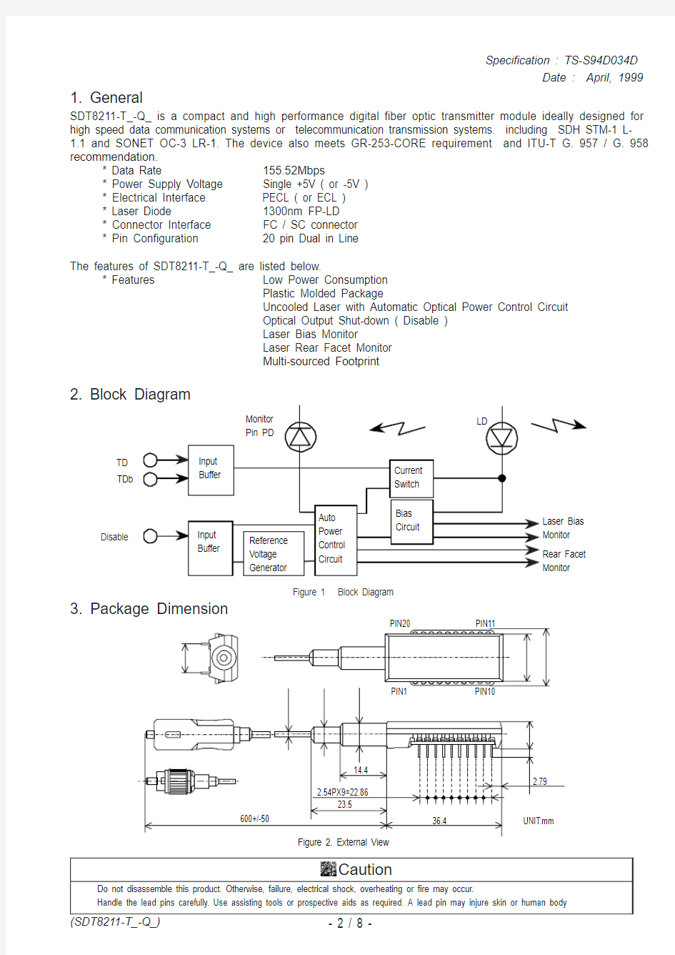
2. Block Diagram
3. Package Dimension
Caution
Do not disassemble this product. Otherwise, failure, electrical shock, overheating or fire may occur.
Handle the lead pins carefully. Use assisting tools or prospective aids as required. A lead pin may injure skin or human body
Disable
Figure 1 Block Diagram
TD TDb
4. Pin Assignment
5. Absolute Maximum Ratings
Warning
Use the product with the rated voltage described in the specification. If the voltage exceeds the maximum rating, overheating or fire may occur.
Caution
Do not store the product in the area where temperature exceeds the maximum rating, where there is too much moisture or dampness,where there is acid gas or corrosive gas, or other extreme conditions. Otherwise, failure, overheating or fire may occur.
1. No condensation allowed
2. SDT8211-T_-QN
3. SDT8211-T_-QW
4. Vcc > Vee, Vee = GND for Vcc = +5V or Vcc = GND for Vee = -5V.
5. TD, TDb and Disable
6. Measured on lead-pin at 2mm off of the package bottom.
Caution
Do not store the product in the area where temperature exceeds the maximum rating, where there is too much moisture or dampness,where there is acid gas or corrosive gas, or other extreme conditions. Otherwise, failure, overheating or fire may occur.
Warning
Use the product with the rated voltage described in the specification. If the voltage exceeds the maximum rating, overheating or fire may occur.
Note 1. Input bias current is not included in Supply Current. 155.52Mbps. 2. 50% duty cycle data
3. Vcc-Vee=5V
4. Tc=25°C
5. 10-90%
6. The transmitter is enabled as default state and requires an external voltage only to disable. ( Refer to 9. Relation between Disable Input Voltage and Optical Output Power )
7. The Laser Bias and Rear Facet Monitor currents are calculated as ratios of the corresponding voltages to thier current-sensing resistors, 10? and 200?, respectively ( See Figure 3 ). Upon measuring or utilizing these values, use a device whose input impedance is high enough ( >1M ?
) compared with those resistors.
0.00
0.15
0.35
0.65
0.85
1.00
-0.20
0.00
0.200.500.801.001.20
Time ( UI )
N o r m a r i z e d A m p l i t u d e
Figure 4 Eye Mask for Optical Output with Fourth Order
Bessel-Thomson Filter Specified in ITU-T G.957
Pin 2
Pin 4
Pin 19
Pin 17
Figure 3 Monitor Circuit Schematic Diagram
9. Relation between Disable Input Voltage and Optical Output Power
8. Relation between Input Signal and Optical Output Power
10. Fiber Pigtail Specification
Warning
Do not look at the laser beam projection area (e.g. end of optical connector) with naked eyes or through optical equipment while the power is supplied to this product. Otherwise, your eyes may be injured.
Caution
Do not give undue force or impact to the optical fiber pigtail. A broken optical fiber may injure skin or human body, or a strong laser beam may cause eye injury. Operate the equipment carefully. Use assisting tools or prospective aids as required.
3. SDT8211-T_-QN
4. SDT8211-T_-QW : Center wavelength value is wider than SONET/SDH specification, but long reach transmission is guaranteed because the spectral width is limited to 2.5nm.
11. Recommended User Interface
https://www.360docs.net/doc/641973595.html,ser Safety
This product uses a semiconductor laser system and is a laser class 1 product acc. FDA, complies with 21CFR1040. 10 and 1040.11.Also this product is a laser class 1 product acc. IEC 825-1.
Caution
If this product is used under conditions not recommended in the specification or this product is used with unauthorized revision,
classfication for laser product safety standard is invalid. Classify the product again at your responsibility and take appropriate actions.
14. Ordering Information
15. Other Precaution
Under such a strong vibration environment as in automobile, the performance and reliability are not guaranteed.
The governmental approval is required to export this product to other countries. To dispose of these components, the appropriate procedure should be taken to prevent illegal exportation.
This module must be handled, used and disposed of according to your company's safe working practice.