Effect of a transverse magnetic field on structure in directional solidified Sn–Pb alloys
Effect of a transverse magnetic?eld on solidi?cation structure in
directionally solidi?ed Sn–Pb hypoeutectic alloys
Dafan Du a,Zhenyuan Lu a,Annie Gagnoud b,Yves Fautrelle b,Zhongming Ren a,
Xionggang Lu a,Rene Moreau b,Xi Li a,b,n
a Department of Material Science and Engineering,Shanghai University,Shanghai200072,PR China
b SIMAP-EPM-Madylam/G-INP/CNRS,PHELMA,BP75,38402St Martin d’Heres Cedex,France
a r t i c l e i n f o
Article history:
Received19April2014
Accepted11June2014
Communicated by M.Rettenmayr
Available online26June2014
Keywords:
A1.Directional solidi?cation
A1.Transverse magnetic?eld
A2.Dendrite spacing
B1.Segregation
B1.Sn–Pb alloys
a b s t r a c t
Effect of a transverse magnetic?eld on the macrosegregation and the growth of the Sn dendrite in the
directionally solidi?ed Sn–Pb alloys was investigated experimentally.The results indicated that the
magnetic?eld modi?ed the shape of the liquid/solid interface and the dendrite morphology signi?-
cantly.Indeed,the application of the magnetic?eld caused the formation of the sloping interface and the
re?nement of the dendrite.It is also found that the magnetic?eld decreased the mushy zone length.
These effects were enhanced with the increase of the magnetic?eld intensity and the decrease of the
growth speed.Further,the Seebeck thermoelectric force(E S)at the liquid/solid interface in the Sn-20wt
%Pb alloy was measured in-situ and the results indicated that the value of the Seebeck thermoelectric
force was about1m V.The modi?cation of the solidi?cation structure during directional solidi?cation
under the magnetic?eld may be attributed to the interdendritic thermoelectric magnetic convection
(TEMC).
&2014Published by Elsevier B.V.
1.Introduction
Solidi?cation processing is one of the important routes to
produce materials as it is not only widely used for shaping materials
to desired products but also for controlling the macro-and micro-
structures,which are intimately related to the?nal properties of
alloys.Convection effects often play a crucial role in most crystal
growth studies at low velocities[1–3].As the magnetic?eld is
capable of damping the melt convection,the effect of the magnetic
?eld on solidi?cation structure has been investigated for several
decades[4–6].However,Boettinger et al.[5]found that no in?uence
on the microstructure was detected during the directional solidi?-
cation of the Pb-57wt%Sn alloy under a transverse or an axial
magnetic?eld of0.1T.Tewari et al.[3]studied the effect of a
stronger transverse magnetic?eld of0.45T on cellular array in the
directionally solidi?ed hypoeutectic Pb-17.7wt%Sn alloy and the
results showed that the cellular array was severely distorted at a
lower growth speed(R r1μm/s).Alboussiere[7]and Laskar[8]
systematically studied the effect of the magnetic?eld on solidifying
Bi-60wt%Sn and Cu-45wt%Ag alloys,and suggested that convec-
tion could arise during directional solidi?cation in the presence
of the magnetic?eld.They proposed that the convection was
produced by the interaction between the magnetic?eld and
thermoelectric(TE)effects.Subsequently,Lehmann et al.[6]gave
quantitative experiments of the so-called thermoelectric magnetic
convection(TEMC)effect.In our previous works,the in?uence of a
static axial magnetic?eld on liquid/solid interface shape and
cellular morphology has been investigated[9],and the experimen-
tal results showed that a weak magnetic?eld(B r0.5T)caused the
formation of the ring-like structure.Present work aims to investi-
gate the in?uence of a transverse magnetic?eld on the macro-
segregation and the Sn-dendrite growth in the directionally solidi?ed
Sn-20wt%Pb alloy.It is found that the sloping interface is formed
during directional solidi?cation under a transverse magnetic?eld.
Moreover,the application of the magnetic?eld caused the
decrease of the dendrite spacing and the mushy zone length at
the same time.This effect was enhanced with the increase of the
magnetic?eld intensity.We attributed the above results to the
thermoelectric magnetic convection(TEMC)in the mushy zone
during directional solidi?cation under the magnetic?eld.Present
work may deepen the understanding of the effect of the magnetic
?eld and the convection on the solidi?cation structures during
directional solidi?cation.
2.Experiment
The samples of the Sn-20wt%Pb and Sn-5wt%Pb alloys used
in this study were prepared with high-purity Sn(99.99%)and
Contents lists available at ScienceDirect
journal homepage:https://www.360docs.net/doc/634086438.html,/locate/jcrysgro
Journal of Crystal Growth
https://www.360docs.net/doc/634086438.html,/10.1016/j.jcrysgro.2014.06.031
0022-0248/&2014Published by Elsevier
B.V.
n Corresponding author.Tel.:+86330476825242;fax:+86330476825211.
E-mail address:lx_net@https://www.360docs.net/doc/634086438.html,(X.Li).
Journal of Crystal Growth402(2014)319–324
500μm 500μm 500μm
B
B
500μm
500μm
500μm
B B
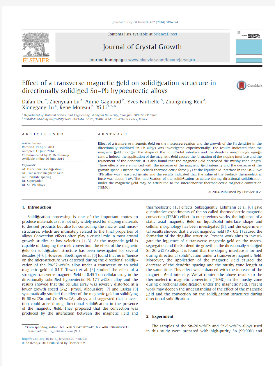
Fig.1.Microstructures near the liquid/solid interface in the directionally solidi ?ed Sn-20wt%Pb alloys at a growth speed of 1μm/s under transverse magnetic ?elds with various intensities:(a,d)0T,(b,e)0.1T,and (c,f)0.6T.
500μm
500μm
500μm
500μm
500μm 500μm
B
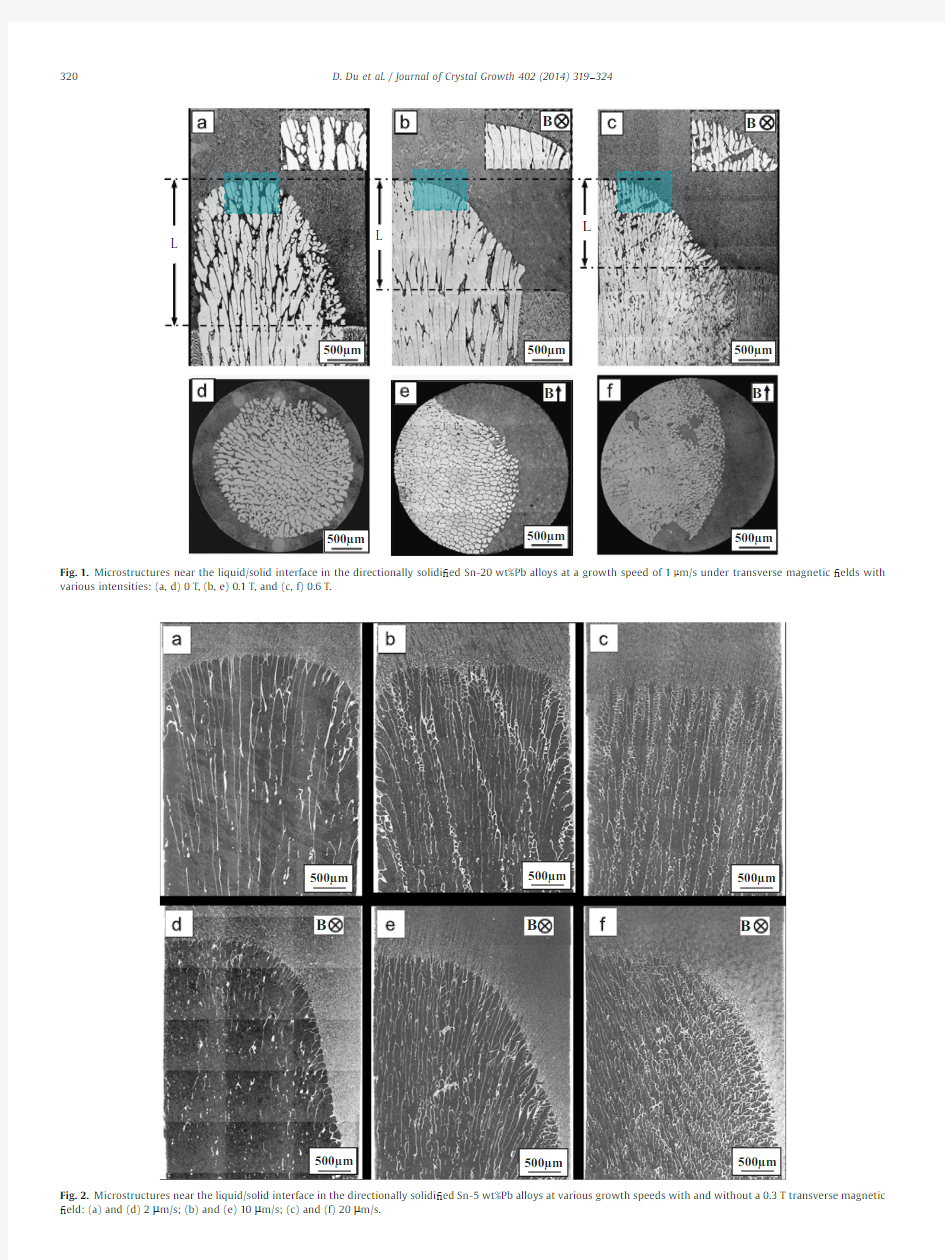
B B Fig.2.Microstructures near the liquid/solid interface in the directionally solidi ?ed Sn-5wt%Pb alloys at various growth speeds with and without a 0.3T transverse magnetic ?eld:(a)and (d)2μm/s;(b)and (e)10μm/s;(c)and (f)20μm/s.
D.Du et al./Journal of Crystal Growth 402(2014)319–324
320
Pb (99.99%)in an induction furnace.The alloys were placed in a high-purity graphite crucible and heated to 6001C,magnetically stirred for half an hour and poured into a graphite mold to cast samples with 3mm in diameter and 200mm in length.The cast sample was enveloped in a high-purity corundum tube with an inner diameter of 3mm and a length of 200mm for the directional
solidi ?cation experiment.The samples were directionally solidi-?ed in a Bridgman apparatus at a speci ?ed growth speed.The experimental apparatus consists of a static electromagnet,a Bridgman –Stockbarge-type furnace and a growth velocity and temperature controller.The electromagnet can produce a trans-verse static magnetic ?eld with an adjustable intensity up to 1T.A water-cooled cylinder containing liquid Ga –In –Sn metal (LMC)was used to cool the specimen.The furnace chamber is controlled by NiSi –NiCr thermocouples with the precision of 71K.The apparatus is designed such that the specimen moves downward while the furnace remains stationary.In order to observe the morphology of the solid/liquid interface during solidi ?cation process,quenching experiments are carried out by quickly with-drawing the specimen into the LMC cylinder to cool the specimen immediately to room temperature.The samples obtained from the experiments were examined in etched condition by the optical microscope.The distribution of the Sn contents in the mushy zone was measured by using a ?eld-emission scanning electron micro-scope (SEM;SU-70,HITACHI)equipped with an energy dispersive X-ray spectrometer (EDS;Genesis APEX2,AMETEK).
3.Results
Fig.1shows the structures near the liquid/solid interface in the directionally solidi ?ed Sn-20wt%Pb hypoeutectic alloy at a growth speed of 1μm/s under various transverse magnetic ?elds.It can be observed that in the case of no magnetic ?eld,the dendrite morphology is typically a columnar dendrite with a signi ?cant macroscopic curvature due to the radial concentration variation caused by thermosolutal convection.However,when the magnetic ?eld was applied,the dendrite morphology and the interface shape were modi ?ed dramatically.Indeed,one can notice that the Sn-dendrite is re ?ned and the interface becomes sloping.It is also found that the mushy zone length decreases under the magnetic ?eld.Fig.2shows the structures near the liquid/solid interface in the directionally solidi ?ed Sn-5wt%Pb hypoeutectic alloy at various growth speeds with and without a 0.3T transverse magnetic ?eld.An application of the magnetic ?eld caused the formation of the sloping liquid/solid interface and the decrease of the dendrite spacing.Fig.3shows the mushy zone length and the primary dendrite spacing as a function of the magnetic ?eld.It can be learned that the length of the mushy zone (L )and the primary dendrite spacing (λ)decrease as the magnetic ?eld increases.At a
40
6080100
120140
1400
1600180020002200
24002600B
(T)
L (μm )
B (T)
λ (μm )
Fig.3.Effect of the magnetic ?eld on the mushy zone length (L )and the primary dendrite spacing (λ)in the Sn-20wt%Pb alloys.(a)The mushy zone length (L)vs the magnetic ?eld intensity (B )and (b)the dendrite spacing (λ)vs the magnetic ?eld intensity (B ).
2000400060008000
1000012000
14000
Distance (μm)
C o n t
Fig.4.(a)EDS analysis for the distributions of the Sn contents at 300μm above the eutectic isothermal of the samples directionally solidi ?ed at a growth speed of 1μm/s under various magnetic ?elds and (b)schematic sketch for the measurement position.
D.Du et al./Journal of Crystal Growth 402(2014)319–324321
lower growth speed of 1μm/s,the dendrite spacing decreases by 46%with an increase in the ?eld from 0to 0.6T,and the value is 42%at a higher growth speed of 10μm/s.
Furthermore,the effect of the magnetic ?eld on the distribution of the Sn contents in the mushy zone was investigated.Fig.4(a)shows the distribution of the Sn contents in the mushy zone at the position of 300μm above the eutectic isothermal and the measurement position is shown in Fig.4(b).The comparison of the distribution of the Sn contents under various magnetic ?elds shows that the macrosegregation formed under a transverse magnetic ?eld and the segregation region increases with the increase of magnetic ?eld intensity.The above results indicate that a transverse magnetic ?eld has affected the distribution of the Pb solute at the crucible scale.
Fig.5(a)shows the microstructures during decreasing the magnetic ?eld from 0.5T to 0T after the steady-state growth for 60mm with the magnetic ?eld.Fig.5(b)shows the transverse microstructures at various positions corresponding to Fig.5(a).It is evident that the Sn-dendrite clusters on the left side of crucible under the magnetic ?eld,and then the clustering dendrites extend to the center of the crucible gradually during decreasing the magnetic ?eld process.Fig.5(c)shows the microstructure evolu-tion in increasing the magnetic ?eld.It can be seen that along with the re ?nement of the dendrite,the dendrite clusters toward the left side of crucible during increasing the magnetic ?eld.The above result further proves that the application of a transverse magnetic ?eld during directional solidi ?cation has signi ?cantly affected the solidi ?cation structure.
4.Discussions
The above results may be attributed to the formation of the interdenritic thermoelectric magnetic convection (TEMC)in the
mushy zone during directional solidi ?cation under a static mag-netic ?eld.It is well known that,in any material,a temperature gradient ?T produces a Seebeck electromotive force S ?T ,where S is the thermoelectric power of the material [10].Fig.6(a)illustrates the principal of Seebeck effect where temperature differences are converted to electricity.It is composed of two electrically conducting materials:one n-type and the other p-type.They are joined at the top by a metal (black bar)to make a junction.When the junction is instead heated,both types of carriers conduct heat to the cold base and a voltage difference is generated at the two base electrodes.If two doped semiconduct-ing materials joined together,the thermoelectric current will ?ow from the n-type material to the p-type at the heater junction.As the thermoelectric power (S )of the liquid phase is large than the solid phase (S L 4S S )[11],a simple analogy was gained:the liquid phase in the mushy zone can be considered as p-type and the solid phase will be n-type.Thus,the current as shown in Fig.6(b)will form.The Seebeck electromotive force (E S )between the solid and melt during directional solidi ?cation can be directly expressed by the equation:E S ?ηsl G T
e1T
where n sl is the effective liquid/solid thermoelectric power differ-ence and G T is the temperature gradient.In order to con ?rm the existence of the liquid/solid thermoelectric power difference during directional solidi ?cation of the Sn –Pb alloys,we have measured in-situ the Seebeck thermoelectric force of the Sn-20wt%Pb alloy.The basic principle of the interfacial thermo-electric measurement using the Seebeck technique was schemati-cally presented in Fig.7(a).The details of the principle had been discussed in Refs.[12,13].Fig.7(b)shows the Seebeck response obtained for the Sn-20wt%Pb alloy at a growth speed of 5m m/s.One can learn that a plateau is obtained on the Seebeck curve
to
500μm
500μm
Fig.5.Structure evolution in the directionally solidi ?ed Sn-20wt%Pb alloy at a growth speed of 2μm/s during decreasing and increasing the magnetic ?eld.(a)Longitudinal microstructures in decreasing the magnetic ?eld from 0.5T to 0T;(b)transverse microstructures corresponding to (a);and (c)longitudinal microstructures in increasing the magnetic ?eld from 0T to 0.5T.
D.Du et al./Journal of Crystal Growth 402(2014)319–324
322
indicate establishment of steady state,and then the signal drops to a new steady state when the furnace translation is shut off.The magnitude of signal drop,E S ,corresponds directly to the effective liquid/solid thermoelectric power difference (ηsl ).This indicates that there indeed exists a liquid/solid thermoelectric power difference during directional solidi ?cation of the Sn-20wt%Pb alloy.Therefore,it is reasonable to attribute the modi ?cation of the solidi ?cation structure during directional solidi ?cation in the magnetic ?eld to the thermoelectric magnetic effects.
Generally,for vertical Bridgman crystal growth of the Sn –Pb hypoeutectic alloys with the melt above the crystal,the heavier species Pb migrates down to the protruding liquid/solid interface due to the gravitational force.Since the solidi ?cation temperature decreases as the local concentration of the heavier species Pb increases,the solidi ?cation temperature for a Pb-rich melt at the ampoule wall is lower than that for the Sn-rich melt at the centerline,leading to a crystal –melt interface which is far more protruding than the local isothermal surfaces,as shown in Fig.6(c).However,when a transverse magnetic ?eld is applied during directional solidi ?cation,the unidirectional TEMC and the corre-sponding recirculation loops will be induced,as shown in Fig.6(d).They will cause the heavier species Pb migrates along the direction of the TEMC and lead to the formation of the sloping interface.
The effect of the convection on the dendrite/cell spacing has ever been studied.Lehmann et al.[14]proposed relating the primary arm spacing to ?ow velocity U which is parallel to the
primary arm as follows:
λ?λ0
???????????????????
?1teU =R T
p e2T
where λ0is the primary spacing without convection,U velocity
and R growth speed.This expression shows that convection reduces the primary arm spacing.Similarly,as the application of the magnetic ?eld during directional solidi ?cation induces the TEMC,the magnetic ?eld will decrease the cell/dendrite spacing.The mushy zone length,d ,is de ?ned as the distance between the tip and the root of a dendrite https://www.360docs.net/doc/634086438.html,ing the constitutional supercooling criterion for binary alloy systems in the absence of convection,d is given by d %m eC E àC 0T=G
e3T
where C E is eutectic composition,m the liquidus slope,C 0the composition of the alloy and G is the temperature gradient.It is not dif ?cult to understand that the interdendritic TEMC enhances the rate of heat-transfer and increases the temperature gradient (G ).Therefore,the decrease in the mushy zone length under a magnetic ?eld may be attributed to the enhancement of the heat-transfer rate caused by the interdendritic TEMC.
In our previous studies [9],it has been found that the value of the TEMC increases to a maximum when the magnetic ?eld reaches a critical value and then decreases as the magnetic ?eld still increases.This critical magnetic ?eld is determined by the
T+T
P
G
N
ΔΔFig.6.Schematic sketch of the TEMC and its effect on the solidi ?cation structure during directional solidi ?cation of the Sn-20wt%Pb alloy under a transverse magnetic ?eld.(a)Seebeck effects;(b)TE current and TEMC near the liquid/solid interface;(c)natural convection in the case of no ?eld and its effect on the distribution of the solute and the solid –liquid interface shape (symbols ‘t’and ‘à’indicate excess and de ?ciency of Pb solute);and (d)solute segregation and the formation of the slopping interface caused by the TEMC.
D.Du et al./Journal of Crystal Growth 402(2014)319–324323
Hartmann number (Ha )Ha ?eσ=ρνT1=2BR
e4T
where νand R ,respectively,denote the kinematic viscosity and typical length scale.The value of Ha corresponding to the critical magnetic ?eld is about 10[15].Here,the critical magnetic ?eld for the interdendritic TEMC during directional solidi ?cation of the Sn –Pb alloys was evaluated.The physical properties used in the
evaluations are presented in Table 1.Evaluation results reveal that the critical magnetic ?eld is about 1.5T for the Sn –Pb alloys.This means that value of the interdendritic TEMC increases with the increase of the magnetic ?eld intensity when the applied magnetic ?eld is less than 1.5T.The dendrite spacing and the mushy zone length decrease as the magnetic ?eld when the applied magnetic ?eld is less than 1.5T (see Figs.1and 3).5.Conclusions
The effect of a transverse magnetic ?eld on the solidi ?cation structure in the directionally solidi ?ed Sn –Pb alloys was studied and the results obtained are summarized as follows:
1.The magnetic ?eld modi ?ed the shape of the liquid/solid interfaces and dendrite morphology and caused the formation of the sloping liquid/solid interfaces.
2.The magnetic ?eld decreased the mushy zone length and the dendrite spacing.The above effect was enhanced with the increase of the magnetic ?eld when the applied magnetic ?eld is less than 0.6T.
3.The Seebeck thermoelectric force (E S )at the liquid/solid inter-face of the Sn-20wt%Pb alloy was measured in-situ and the results indicated that the value of the Seebeck thermoelectric force is about 1m V.
4.The above results may be attributed to the interdendritic thermoelectric magnetic convection (TEMC)in the mushy zone.
Acknowledgments
This work is supported partly by the European Space Agency through the Bl-inter 09_473220,National Natural Science Founda-tion of China (Nos.51271109and 51171106),and the Program for Professor of Special Appointment (Eastern Scholar)at Shanghai Institutions of Higher Learning.References
[1]J.T.Mason,J.D.Verhoeven,R.Trivedi,Metall.Trans.A 15(1984)1665.[2]M.D.Dupouy,D.Camel,J.J.Favier,Acta.Metall.Mater.40(1992)991.[3]S.N.Tewari,R.Shah,M.A.Chopra,Metall.Trans.A 24(1993)1661.[4]H.A.Chedzey,D.T.J.Hurle,Nature 210(1966)933.
[5]W.J.Boettinger,F.Biancaniello,S.Coriell,Metall.Trans.A 12A (1981)321.[6]P.Lehmann,R.Moreau,D.Camel,R.Bolcato,Acta Mater.46(1998)4067.[7]T.Alboussiere,R.Moreau,https://www.360docs.net/doc/634086438.html,pte,Rendu de l ’Acad.Sci.313(1991)749.[8]https://www.360docs.net/doc/634086438.html,skar,Thesis,INPG,France,1994.
[9]X.Li,Y.Fautrelle,Z.M.Ren,Acta Mater.55(2007)3803.[10]J.A.Shercliff,Fluid Mech.91(1979)231.
[11]I.Kaldre,Y.Fautrelle,J.Etay,A.Bojarevics,L.Buligins,Modern Phys.Lett.25(2011)731.
[12]A.Rouzaud,https://www.360docs.net/doc/634086438.html,era,P.Contamin,B.Angelier,F.Herbillon,J.J.Favier,J.Cryst.Growth 129(1993)173.
[13]J.J.Favier,J.P.Garandet,A.Rouzaud,D.Camel,J.Cryst.Growth 140(1994)237.[14]P.Lehmann,R.Moreau,D.Camel,J.Cryst.Growth 183(1998)690.[15]
Y.Y.Khine,J.S.Walker,J.Cryst.Growth 183(1998)150
.
0.6
0.81.01.21.41.6
1.8
2.0
Time (Min)
S e e b e c k S i g n a l (μV )
Fig.7.(a)An illustration of the principle of interfacial thermoelectric measurement using the Seebeck technique and (b)Seebeck response obtained for the Sn-20wt%Pb alloy directionally solidi ?ed at a growth speed of 5μm/s.
Table 1
Physical properties of the Sn –Pb alloys used in the evaluation [14].Properties
Magnitude
Electrical conductivity of solid Sn (σS ,Ωà1m à1)
6.3?106Electrical conductivity of liquid (σL ,
Ωà1m à1)
7?106
Thermoelectric power of liquid (S L ,νK à1)(553K)à0.109?10à6Thermoelectric power of solid Sn (S S ,νK à1)(456K)
à0.219?10à6
Temperature gradient (G ,K m à1)78?102Kinematic viscosity (ν,m s à1) 1.34?10à7Density (ρ,kg m à3)
7.7?103
D.Du et al./Journal of Crystal Growth 402(2014)319–324
324
电源磁芯尺寸功率参数.doc
电源磁芯尺寸功率参数
常用电源磁芯参数 MnZn 功率铁氧体 EPC 功率磁芯 特点:具有热阻小、衰耗小、功率大、工作频率宽、重量 轻、结构合理、易表面贴装、屏蔽效果好等优点,但散热 性能稍差。 用途:广泛应用于体积小而功率大且有屏蔽和电磁兼容要 求的变压器,如精密仪器、程控交换机模块电源、导航设 备等。 EPC型功率磁芯尺寸规格 磁芯型号Type 尺寸Dimensions(mm) A B C D Emin F G Hmin EPC10/8 10.20±0.20 4.05±0.30 3.40±0.20 5.00±0.20 7.60 2.65±0.20 1.90±0.20 5.30 EPC13/13 13.30±0.30 6.60±0.30 4.60±0.20 5.60±0.20 10.50 4.50±0.30 2.05±0.20 8.30 EPC17/17 17.60±0.50 8.55±0.30 6.00±0.30 7.70±0.30 14.30 6.05±0.30 2.80±0.20 11.50 EPC19/20 19.60±0.50 9.75±0.30 6.00±0.30 8.50±0.30 15.80 7.25±0.30 2.50±0.20 13.10 EPC25/25 25.10±0.50 12.50±0.30 8.00±0.30 11.50±0.30 20.65 9.00±0.30 4.00±0.20 17.00 EPC27/32 27.10±0.50 16.00±0.30 8.00±0.30 13.00±0.30 21.60 12.00±0.30 4.00±0.20 18.50 EPC30/35 30.10±0.50 17.50±0.30 8.00±0.30 15.00±0.30 23.60 13.00±0.30 4.00±0.20 19.50 EPC39/39 39.00±0.50 19.60±0.30 15.60±0.30 18.00±0.30 30.70 14.00±0.30 10.00±0.30 24.50 EPC42/44 42.40±1.00 22.00±0.30 15.00±0.40 17.00±0.30 33.50 16.00±0.30 7.40±0.30 26.50
公路电动栏杆机控制模块维修简述
公路电动栏杆机控制模块维修简述 目前,公路自动栏杆机控制模块主要是Magnetic的自动栏杆机控制模块,这种控制模块采用了先进的微处理器技术和可靠的开关控制技术,系统集成度高,逻辑功能强,满足公路环境下的应用。 下面简单介绍栏杆机控制模块面板的功能与接线,栏杆机控制模块中的数字代表意义和接法如下: “1”表示接电源L(火线)220V AC; “2”表示接电源N(零线); “3”表示电源线地线; “4”表示电机接地线PE; “5”表示电机公共绕组U,接电机公共绕组U; “6”表示电机落杆绕组V,接电机绕组V; “7”表示电机升杆绕组W,接电机绕组W; “8、9”表示降压减速阻容(R=5Ω/25W C=2uF/AC450V,电阻和电容串联); “10、11”表示电机运行电容(4uF/AC450V); “17”表示电源输出24VDC接地线; “18”表示电源输出 24VDC正极; “19”表示控制信号共用线(+24VDC); “20”表示开脉冲,和控制信号共用线(+24VDC)短接有效; “21”表示环路感应器2输入(用于车辆到时自动抬杆,用于6、8模式); “22”表示关脉冲,和控制信号共用线(+24VDC)短接有效; “23”表示抬杆、落杆限位开关输入信号; “24”表示安全开关,接常闭触点;断开时,系统不会执行落杆动作; “25”表示控制信号共用线(+24VDC),同“19”功能一样; “26”表示档杆状态输出公共触点; “27、28”完全等同于“20、22”,常开触点(300ms); “29”表示抬杆状态输出触点; “30”表示落杆状态输出触点; “31、32”表示报警输出,为常开触点。 栏杆机控制模块长期处于工作状态,每天控制栏杆上下达几千次以上,是栏杆机易损元件之一,下面简单介绍几点常见的故障和维修方法,供大家参考: 首先,在维修栏杆机控制模块之前,务必将故障设备的灰尘清除干净,养成这个习惯可以让你检查和维修故障更快速、准确。 故障一控制模块无电现象 控制模块电源长期处于带电中,供电系统元件容易老化,容易出现无供电现象。这种情况一般先观察,所谓观察就是用眼睛看。注意观察栏杆机控制模块的外观、形状上有无什么异常,电器元件(如变压器、电容、电阻等)有无出现变形、断裂、松动、磨损、冒烟、腐蚀等情况。 其次是鼻子闻,一般轻微的气昧是正常的,如果有刺鼻的焦味,说明某个元器件被烧坏或击穿,应替换相应的元器件。最后用手试,当然是触摸绝缘的部分,有无发热或过热,用手去试接头有无松动,以确定设备运行状况以及发生故障的性质和程度。 如某站01#车道出现控制模块无电,经测试是电源保险管(250V 4A)烧毁。在更换前
各种开关电源变压器各种高频变压器参数EEEEEEEIEI等等的参数
功率铁氧体磁芯 常用功率铁氧体材料牌号技术参数 EI型磁芯规格及参数
PQ型磁芯规格及参数 EE型磁芯规格及参数 EC、EER型磁芯规格及参数
1,磁芯向有效截面积:Ae 2,磁芯向有效磁路长度:le 3,相对幅值磁导率:μa 4,饱和磁通密度:Bs 1磁芯损耗:正弦波与矩形波比较 一般情况下,磁芯损耗曲线是按正弦波+/-交流(AC)激励绘制的,在标准的和正常的时候,是不提供极大值曲线的。涉及到开关电源电路设计的一个共同问题是正弦波和矩形波激励的磁芯损耗的关系。对于高电阻率的磁性材料如类似铁氧体,正弦波和矩形波产生的损耗几乎是相等的,但矩形波的损耗稍微小一些。材料中存在高的涡流损耗(如大 一般情况下,具有矩形波的磁芯损耗比具有正弦波的磁芯损耗低一些。但在元件存在铜损的情况下,这是不正确的。在变压器中,用矩形波激励时的铜损远远大于用正弦波激励时的铜损。高频元件的损耗在铜损方面显得更多,集肤效应损耗比矩形波激励磁芯的损耗给人们的印象更深刻。举个例子,在 20kHz、用17#美国线规导线的绕组时,矩形波激励的磁芯损耗几乎是正弦波激
励磁芯损耗的两倍。例如,对于许多开关电源来说,具有矩形波激励磁芯的 5V、20A和30A输出的电源,必须采用多股绞线或利兹(Litz)线绕制线圈,不能使用粗的单股导线。 2Q值曲线 所有磁性材料制造厂商公布的Q值曲线都是低损耗滤波器用材料的典型曲线。这些测试参数通常是用置于磁芯上的最适用的绕组完成的。对于罐形磁芯,Q值曲线指出了用作生成曲线时的绕组匝数和导线尺寸,导线是常用的利兹线,并且绕满在线圈骨架上。 对于钼坡莫合金磁粉芯同样是正确的。用最适合的绕组,并且导线绕满了磁芯窗口时测试,则Q值曲线是标准的。Q值曲线是在典型值为5高斯或更低的低交流(AC)激励电平下测量得出的。由于在磁通密度越高时磁芯的损耗越大,故人们警告,在滤波电感器工作在高磁通密度时,磁芯的Q值是较低的。3电感量、AL系数和磁导率 在正常情况下,磁芯制造厂商会发布电感器和滤波器磁芯的AL系数、电感量和磁导率等参数。这些AL的极限值建立在初始磁导率范围或者低磁通密度的基础上。对于测试AL系数,这是很重要的,测试AL系数是在低磁通密度下实施的。 某些质量管理引入检验部门,希望由他们用几匝绕组检查磁芯,并用不能控制频率或激励电压的数字电桥测试磁芯。几乎毫不例外,以几百高斯、若干
磁芯参数参看
z变压器基础知识 1、变压器组成: 原边(初级primary side ) 绕组 副边绕组(次级secondary side ) 原边电感(励磁电感)‐‐magnetizing inductance 漏感‐‐‐leakage inductance 副边开路或者短路测量原边 电感分别得励磁电感和漏感 匝数比:K=Np/Ns=V1/V2 2、变压器的构成以及作用: 1)电气隔离 2)储能 3)变压 4)变流 ●高频变压器设计程序: 1.磁芯材料 2.磁芯结构 3.磁芯参数 4.线圈参数 5.组装结构 6.温升校核 1.磁芯材料 软磁铁氧体由于自身的特点在开关电源中应用很广泛。 其优点是电阻率高、交流涡流损耗小,价格便宜,易加 工成各种形状的磁芯。缺点是工作磁通密度低,磁导率 不高,磁致伸缩大,对温度变化比较敏感。选择哪一类 软磁铁氧体材料更能全面满足高频变压器的设计要求, 进行认真考虑,才可以使设计出来的变压器达到比较理 想的性能价格比。 2.磁芯结构 选择磁芯结构时考虑的因数有:降低漏磁和漏感, 增加线圈散热面积,有利于屏蔽,线圈绕线容易,装配 接线方便等。 漏磁和漏感与磁芯结构有直接关系。如果磁芯不需 要气隙,则尽可能采用封闭的环形和方框型结构磁芯。 3.磁芯参数: 磁芯参数设计中,要特别注意工作磁通密度不只是受磁化曲线限制,还要受损耗的限制,同时还与功率传送的工作方式有关。 磁通单方向变化时:ΔB=Bs‐Br,既受饱和磁通密度限制,又更主要是受损耗限制,(损耗引起温升,温升又会影响磁通密度)。工作磁通密度Bm=0.6~0.7ΔB 开气隙可以降低Br,以增大磁通密度变化值ΔB,开气隙后,励磁电流有所增加,但是可以减小磁芯体积。对于磁通双向工作而言: 最大的工作磁通密度Bm,ΔB=2Bm。在双方向变化工作模式时,还要注意由于各种原因造成励磁的正负变化的伏秒面积不相等,而出现直流偏磁问题。可以在磁芯中加一个小气隙,或者在电路设计时加隔直流电容。 4.线圈参数: 线圈参数包括:匝数,导线截面(直径),导线形式,绕组排列和绝缘安排。 导线截面(直径)决定于绕组的电流密度。通常取J为2.5~4A/mm2。导线直径的选择还要考虑趋肤效应。如必要,还要经过变压器温升校核后进行必要的调整。 4.线圈参数: 一般用的绕组排列方式:原绕组靠近磁芯,副绕组反馈绕组逐渐向外排列。下面推荐两种绕组排列形式: 1)如果原绕组电压高(例如220V),副绕组电压低,可以采用副绕组靠近磁芯,接着绕反馈绕组,原绕组在最外层的绕组排列形式,这样有利于原绕组对磁芯的绝缘安排; 2)如果要增加原副绕组之间的耦合,可以采用一半原绕组靠近磁芯,接着绕反馈绕组和副绕组,最外层再绕一半原绕组的排列形式,这样有利于减小漏感。 5.组装结构:
栏杆机说明书
MAGSTOP MIB 2O/3O/40 栏杆机 及MAGTRONIC MLC 控制器 操作指导 @1999年马格内梯克控制系统(上海)有限公司 地址:上海浦东新区宁桥路999号二幢底西层邮编:201206 电话:(21)58341717 传真:(21)58991233
目录 1. 系统概述 2 1.1 停车场系统的布局 2 1. 2 系统组件概述 2 2 安全 3 2.1一般安全信息3 2.2 建议用途 3 2.3 本手册中使用的安全标志3 2.4 操作安全 4 2.5 技术发展 4 2.6 质量保证 4 3. 装配及安装 5 3.1 构筑安装地基 5 3.2 安装感应线圈 6 3.3 安装机箱 8 3.4 安装栏杆机臂 8 3.5 基本机械结构 9 3.6 设置及校准弹簧 9 3.7 校准栏杆机臂位置 10 4. 电源连接 10 5. MLC控制器 11 5.1 命令发生器:在不同操作模式下的连接及功能 12 5.2 MLC控制器的操作 14 5.3 MLC控制器显示信息的解释 14 5.4 MLC控制器的复位 14 5.5 栏杆机的操作 15 5.6 编制及读取操作数据 16 5.7 校准感应线圈 18 6. 初始化操作 19 6.1 委托程序 19 6.2 在启动过程中显示的信息 19 7. 技术数据 21 7.1 栏杆机 21 7.2 控制器 21 8. 附录 22 8.1校准角度传感器及优化栏杆机的动作22 8.2 校准安全设备的角度 24 8.3 读取时间计数器 25 8.4 读取操作循环计数器 25 8.5 读取制动设置 25 8.6 复位情况的说明 26 8.7 测试模式 27 8.8 校准传感器 28 9. 技术支持 28 10. 备用零部件 29
单端反激式开关电源磁芯尺寸和类型的选择
单端反激式开关电源磁芯尺寸和类型的选择字体大小:大|中|小2008-08-28 12:53 - 阅读:1655 - 评论:1 单端反激式开关电源磁芯尺寸和类型的选择徐丽红王佰营wbymcs51.blog.bokee .net A、InternationalRectifier 公司--56KHz 输出功率推荐磁芯型号 0---10WEFD15 SEF16 EF16 EPC17 EE19 EF(D)20 EPC25 EF(D)25 10-20WEE19 EPC19 EF(D)20 EE,EI22 EF(D)25 EPC25 20-30WEI25 EF(D)25
EPC25 EPC30 EF(D)30 ETD29 EER28(L) 30-50WEI28 EER28(L) ETD29 EF(D)30 EER35 50-70WEER28L ETD34 EER35 ETD39 70-100WETD34 EER35 ETD39 EER40 E21 摘自 InternationalRectifier,AN1018- “应用 IRIS40xx 系列单片集成开关 IC 开关电源的反激式变压器设计” B、ELYTON公司https://www.360docs.net/doc/634086438.html, 型号输出功率( W) <5 5-10 10-20 20-50 50-100 100-200 200-500 500-1K
EI EI12.5 EI16 EI19 EI25 EI40 -- EI50 EI60 EE EE13 EE16 EE19 EE25 EE40 EE42 EE55 EE65 EF EF12.6 EF16 EF20 EF25 EF30 EF32 EFD -- EFD12 EFD15 EFD20 EFD25 EFD30 EPC -- EPC13 EPC17 EPC19 EPC25 EPC30 EER EER9.5 EER11 EER14.5 EER28 EER35 EER42 EER49 -- ETD ETD29 ETD34 ETD44 ETD49 ETD54 -- EP EP10 EP13 EP17 EP20 -- RM RM4 RM5 RM6 RM10 RM12 POT POT1107 POT1408 POT1811 POT2213POT3019 POT3622 POT4229 -- PQ -- -- -- PQ2016 PQ2625 PQ3230 PQ3535 PQ4040 EC ---------------------------- -- EC35 EC41 EC70 摘自 PowerTransformers OFF-LINE Switch Mode APPLICATION NOTES
高速公路自动栏杆机控制模块维修
高速公路自动栏杆机控制模块维修实例【转贴】 本人在成绵高速公路长期的维护工作中收集、总结的一些关于自动栏杆机控制模块的维护心得,供大家参考。成绵高速公路自动栏杆机控制模块主要是恒富威和magnetic专业设计的自动栏杆机控制模块,主要用于栏杆机的控制。采用了先进的微处理器技术和可靠的开关控制技术,系统集成度高,逻辑功能强,满足高速公路环境下的应用。下面我介绍下栏杆机控制模块面板的功能与接线栏杆机控制模块中的数字代表意义货接法如 下:“1”表示接电源L(火线)220V。“2”表示接电源N (零线)。“3”表示电源线地线。“4”表示电机接地线PE。“5”表示电机公共绕组U;接电机公共绕组U。“6”表示电机落杆绕组V;接电机绕组V。“7”表示电机升杆绕组W;接电机绕组W。“8、9”表示降压减速阻容(R=5Ω/25W C=2uF/AC450V,电阻和电容串联)。“10、11”表示电机运行电容 (4uF/AC450V)。“17”表示24V接地线。“18”表示表示电源+24V。“19”表示控制信号共用线(+24V)。“20”表示开脉冲,和控制信号共用线(+24V)短接有效。“21”表示环路感应器2输入(用于车辆到时自动提杆,用于6、8模式)。“22”表示关脉冲,和控制信号共用线(+24V)短接有效。“23”表示抬杆、落杆限位开关输入信号。“24”示安全开关,接常闭触点;断开时,系统不会执行落杆动作。“25”表示控制信号共用线(+24V),同“19”功能一样。“26”表示档杆状态输出公共触点。“27、28”完全等同于“20、22”表示计数输出,常开触点 (300ms)。“29”表示抬杆状态输出触点。“30”表示落杆状态输出触点。“30、31”表示报警输出,常开触点。栏杆机控制模块长期处于工作状态,每天控制栏杆上下达千次以上;是栏杆机易坏元件之一,下面我介绍常见几点常见的故障和实用的维修方法,供大家参 考。首先,维修设备之前,务必将故障设备的灰尘清除掉,养成这个习惯可以让你维修和检查故障起来轻松、准确许多。 故障一控制模块无电现象控制模块电源长期处于带电中,供电系统元件容易老化,容易出现无供电现象。这种情况一般先观察,所谓观察就是用眼睛看。注意观察栏杆机控制模块的外观、形状上有无什么异常,电器元件,如变压器,电容,电阻等有无出现变形,断裂,松动,磨损,冒烟,腐蚀等情况。其次是鼻子闻,一般轻微的气昧是正常的,如果有刺鼻的焦味,说明某个元器件被烧坏或击穿,应替换相应的元器件。最后用手试,当然是触摸绝缘的部分,有无发热或过热,用手去试接头有无松动;以确定设备运行状况以及发生故障的性质和程度。如某站一道出现控制模块无电,经测试是电源保险管(250V 4A)烧毁。我在更换前观察其他元件外表是否变形断裂,用手触摸电容、电感等接头有无松动。其次我就用万用表跑线,看是否有短路现象。经我检查后初步判定为保险丝被击穿,准备替换。替换前应认清被替换元器件的型号和规格。(同时替换某些元件时还应该注意方向。)最后我将同一型号的保险丝替换上并加电,控制模块工作灯亮起,用外用表测试控制模块,修复。有时,无电现象还由变压器(PIN9 0-115V PIN16 115V-0)损坏造成的。控制模块
Magnetic TOLL栏杆机中文说明书
9 电气连接 9.1 安全 请参照18页,第2.6节“专业安全和特殊危险”中的安全注意事项。 电压 危险 一般 警告
热的表面 小心 电磁干扰 个人保护装备
在施工过程中,必须穿戴以下几种保护装备: ■工作服 ■保护手套 ■安全鞋 ■保护头盔。 9.2安装电保护设备 根据地区或当地的规定,安全设备需要提供给客户。通常有以下几种:■漏电保护器 ■断路器 ■ EN 60947-3的可锁定的2极开关。 9.3连接电源线 电压 危险 注意! 电源线的导线截面在1.5到4mm2 之间。要遵守国家关于 导线长度和相关电缆截面积的规定.
危险! 电压有致命的危险! 1.断开栏杆机系统电源。确保系统断电。确保机器不会再启动。 接线的准备—剥电缆外皮和铁芯绝缘 2.照下图剥开电源线和磁芯 图37:剥电源供应线。 1 电位 2 零线 3 地线 安置电源线 3.照下图,把电源线正确安装在相应的终端线夹上。也可参照,163页,第17.1节的“接线图”。 ■在机箱中正确安装电源线。此电源线不可连接移动部件。 ■用两个束线带固定电源线。 图38 安置电源线 1 电源线
2 束线带 3 束线带的金属突出物 连接电源线 图39:连接电源线 1 电源线的终端线夹 2 电位L 3 零线 N 4 地线 PE 9.4连接控制线路(信号设备) 以下连接对控制和反馈端有效: ■控制栏杆机的8个数码输入 ■反馈信息的4个数码输出 ■反馈信息的6个继电器输出。3个常开,3个转换触点。 危险! 电压有致命危险! 1.断开栏杆机系统电源。确保系统断电并不会重启。 连接控制线 2.将控制线穿过穿线孔。 ■在机箱中合理的放置控制线。控制线不可进入可移动部件。 ■安装控制线夹和绑线。通过轻微按压或移动,线夹可以在轨道上移动到预期的位置。绑线可以绑扎在金属突出物上。 3. 根据接线图连接控制线。请参照163页,第17.1节的“接线图”。
磁芯参数表
常用磁芯参数表 【EER磁芯】 ■ 用途:高频开关电源变压器、匹配变压器、扼流变压器等。 【EE磁芯】 ■ 用途:电源转换用变压器及扼流圈、通讯及其他电子设备变压器、滤波器、电感器及扼流圈、脉冲变压器等。
【ETD磁芯】 ■ 用途:电源转换用变压器及扼流圈、通讯及其他电子设备变压器、滤波器。 【EI 磁芯】 ■ 用途:高频开关电源变压器、功率变压器、整流变压器、电压互感器等。 【ET 磁芯】 ■ 用途:滤波变压器 【EFD 磁芯】 ■ 用途:高频开关电源变压器器、整流变压器、开关变压器等。
【UF 磁芯】 ■ 用途:整流变压器、脉冲变压器、扼流变压器、电源变压器等。 【PQ 磁芯】 ■ 用途高频开关电源变压器、整流变压器等。 【RM 磁芯】 ■ 用途:高频开关电源变压器、整流变压器、屏蔽变压器、脉冲变压器、脉冲功率变压器、扼流变压器、滤波变压器。 【EP 磁芯】 ■ 用途:功率变压器、宽频变压器、屏蔽变压器、脉冲变压器等。
【H 磁芯】 ■ 用途:宽带变压器、脉冲变压器、脉冲功率变压器、隔离变压器、滤波变压器、扼流变压器、匹配变压器等。 软磁铁氧体磁芯形状与尺寸标准(一) 软磁铁氧体磁芯形状 软磁铁氧体是软磁铁氧体材料和软磁铁氧体磁芯的总称。软磁铁氧体磁芯是用软磁铁氧体材料制成的元件或零件,或是由软磁铁氧体材料根据不同形式组成的磁路。磁芯的形状基本上由成型(形)模具决定,而成型(形)模具又根据磁芯的形状进行设计与制造。 磁芯按磁力线的路径大致可分两大类;磁芯按具体形状分,有各种各样: 磁芯按磁力线路径分类 磁芯按使用时磁化过程所产生磁力线的路径可分为开路磁芯和闭路磁芯两类。 第一类为开路磁芯。这类磁芯的磁路是开启的(open magnetic circuits),通过磁芯的磁通同时要通过周围空间(气隙)才能形成闭合磁路。开路磁芯的气隙占磁路总长度的相当部分,磁阻很大,磁路中的部分磁通在达到气隙以前就已离开磁芯形成漏磁通。因而,开路磁芯在磁路各个截面上的磁通不相等,这是开路磁芯的特点。由于开路磁芯存在大的气隙,磁路受到退磁场作用,使磁芯的有效磁导率μe比材料的磁导率μi有所降低,降低的程度决定于磁芯的几何形状及尺寸。 开路磁芯有棒形、螺纹形、管形、片形、轴向引线磁芯等等。IEC 1332《软磁铁氧体材料分类》标准中称开路磁芯为OP类磁芯。 第二类磁芯为闭路磁芯。这类磁芯的磁路是闭合的(closed magnetic circuits),或基本上是闭合的。IEC 1332称闭路磁芯为CL类磁芯。磁路完全闭合的磁芯最典型的是环形磁芯。此外,还有双孔磁芯、多孔磁芯等等。
栏杆机控制器
MLC 580C N ,5131/04.02Phone:+49 7622/695-5Fax:+49 7622/695-602 e-mail:info@ac-magnetic.de https://www.360docs.net/doc/634086438.html,
Magnetic Control Systems Sdn.Bhd.No.16, Jalan Kartunis U1/47Temasya Ind.Park, Section U140150 Shah Alam, Selangor Darul Ehsan, Malaysia Phone:(+60) 3 / 55691718eMail: info@https://www.360docs.net/doc/634086438.html,.my Magnetic Control Systems (Shanghai) Co. Ltd.999 Ning-qiao Road, Bldg. 2W/1F Pudong New Area Shanghai 201206, China Phone:(+86) 21/ 58 341717eMail: magnetic@https://www.360docs.net/doc/634086438.html, Magnetic Automation Pty. Ltd.19 Beverage Drive Tullamarine, Victoria 3043, Australia Phone:(+61) 3 / 93 30 10 33eMail: info@https://www.360docs.net/doc/634086438.html, Magnetic Automation Corp.3160 Murrell Road Rockledge, FL 32955, USA Phone:(+1) 321/ 635 85 85eMail: info@https://www.360docs.net/doc/634086438.html, Magnetic Autocontrol Pvt.Ltd.Calve Chateau, 2B, IInd Floor Kilpauk 322 Poonamallee High Road IND Chennai, 600010 / India Phone:(+91) 44 6400 443eMail: magneticsales@https://www.360docs.net/doc/634086438.html,
德国magnetic栏杆机常见故障分析
德国Magnetic栏杆机的常见故障分析德国Magnetic自动栏杆机的核心部分是MLC控制器,控制器设置的正确与否直接影响栏杆机的正常工作。当栏杆机工作不正常时,请先确认是否是栏杆机的问题,是栏杆机哪个部分出现问题(如机械部分或控制部分),建议先将其他车道工作正常栏杆机控制器换到本车道,以确认是否是控制器出现问题;如果互换控制器后栏杆机工作正常,那么就确认本车道控制器有问题,请参照工作正常的控制器设置即可;如控制器重新设置后仍不能解决问题,请将控制器返回厂家维修。 以下是德国Magnetic自动栏杆机控制器的几种常见设置,可供参考。 1、控制器黑色按键和白色按键的作用: ?黑键:1)、手动控制抬杆; 2)、控制器编程时改变数值; 3)、控制器编程完毕后保存 ?白键:1)、手动控制落杆; 2)、控制器编程时确认数值; 3)、控制器编程完毕后不保存。 ?编程时,同时按下黑键和白键后数值下边出现光标。 ?同时按下黑键和白键持续四秒钟,控制器重启。 2、MLC控制器复位: ?同时按下黑键和白键持续四秒钟; ?将圆盘转至F,确认后可恢复到出厂设置; ?详见中文说明书第14页。 3、控制器圆盘开关各位置的功能 位置0:普通操作模式 位置1:程序代码 1—8
位置2:转矩时间 1—30秒 位置3:栏杆机开启时间 1—255秒 位置4:感应线圈A灵敏度 O一9 (0最小,9最大) 位置5:感应线圈B灵敏度 0—9(0最小,9最大) 位置6:检测器模式A0—8(见功能说明表) 位置7:检测器模式B0—8(见功能说明表) 位置8:感应线圈A/B频率 1 0,000Hz一90,000Hz 位置9:备用 位置A:计数模式 位置B:备用 位置C:备用 位置D:硬件错误控制器 16进制错误代码 位置E:语种选择德、英、法、西 位置F:出厂设置重设所有操作数据 4、模式设置: 将圆盘转至1,控制器有8种操作模式可供选择;详见中文说明书第16页。 5、控制器编程过程: (1)将圆盘开关转到所需位置; (2)同时按下黑色按键和白色按键; (3)使用黑色按键将数字滚动显示为所需的数值(光标位于正在变化的数字下方); (4)按下白色按键存储选中的数值或者将光标移到右边的一格; (5)按下黑色按键确认最终的数值或者按下白色按键取消输入的数值。 注意:完成编程后,请将圆盘开关转回到“0”位置(即普通操作模式) 6、感应线圈灵敏度设置: 将圆盘转至4或5(设置线圈A转至4,线圈B转至5);一般情况下灵敏度选择4-6,不宜太高或太低。详见中文说明书第16页。 7、检测器A、B的开启和关闭 将圆盘开关转至6和7分别设置检测器A、B的状态,如果A、B线圈都没有使用或只使用了一个检测器,那么就要关闭没有使用的检测器(将检测器A、B的数值设置为0,是关闭状态;检测器开启时数值是应该是1或2,一般用2。) 8、校准传感器/优化栏杆机动作
开关电源参数计算
(1)输入电压:185V AC~240V AC (2)输出电压1:+5VDC ,额定电流1A ,最小电流750mA ; (3)输出电压2:+12VDC ,额定电流1A ,最小电流100mA ; (4)输出电压3:-12VDC ,额定电流1A ,最小电流100mA ; (5)输出电压4:+24VDC ,额定电流1.5A ,最小电流250mA ; (6)输出电压纹波:+5V ,±12V :最大100mV (峰峰值);+24V :最大250mV (峰峰值) (7)输出精度:+5V ,±12V :最大± 5%;+24V :最大± 10%; (8)效率:大于80% 3. 参数计算 (1)输出功率: 5V 112V 1224V 1.565 out P A A A W =?+??+?= (3-1) (2)输入功率: 6581.2580%0.8 out in P W P W = == (3-2) (3)直流输入电压: 采用单相桥式不可控整流电路 (max)240VAC 1.414=340VDC in V =? (3-3) (min)185VAC 1.414=262VDC in V =? (3-4) (4)最大平均电流: (m a x ) (m i n )81.25 0.31262in in in P W I A V V == = (3-5) (5)最小平均电流: (min)(max) 81.250.24340 in in in P W I A V = = = (3-6) (6)峰值电流: 可以采用下面两种方法计算,本文采用式(3-8)的方法。
(min)max (min)(min)225581.25 1.550.4262out out out Pk C in in in P P P W I I A V D V V V ?== ====? (3-7) min 5.5 5.581.25 1.71262out Pk C in P W I I A V V ?== == (3-8) (7)散热: 基于MOSFET 的反激式开关电源的经验方法:损耗的35%是由MOSFET 产生,60%是由整流部分产生的。 开关电源的损耗为: (180%)81.25 20%16.25D in P P W W =?-=?= (3-9) MOSFET 损耗为: 35%16.2535% 5.69D MOSFET D P P W W -=?=?= (3-10) 整流部分损耗: (5)55( )60%()16.2560%0.756565D V D W W P P W W W W +=??=??= (3-11) (12)12122()60%2()16.2560% 3.66565D V D W W P P W W W W ±=???=???= (3-12) (242)3636()60%()16.2560% 5.46565D V D W W P P W W W W +=??=??= (3-13) (8)变压器磁芯: 采用天通的EER40/45,饱和磁通密度Bs 在25℃时大于500mT ,在100℃时大于390mT 。窗口有效截面积Ae=152.42mm 2。 所以,取 max 11 0.390.222 s B B T T = =?≈ (3-14) Ae=152.42mm 2 (3-15) (9)开关电源频率: 40f khz = (3-16) (10)开关电源最大占空比: max 0.4D = (3-17)
磁芯各参数详解
一、磁芯初始磁导率 磁感应强度与磁场强度的比值称为磁导率。 初始磁导率高:相同圈数感值大,反之亦然; 初始磁导率高:相同电流下容易饱和,反之亦然; 初始磁导率高:低频特性好,高频差,反之亦然; 初始磁导率高:相同产品价格高,反之亦然; 1、磁导率的测试仪器功能 磁导率的测量是间接测量,测出磁心上绕组线圈的电感量,再用公式计算出磁心材料的磁导率。所以,磁导率的测试仪器就是电感测试仪。在此强调指出,有些简易的电感测试仪器,测试频率不能调,而且测试电压也不能调。例如某些电桥,测试频率为100Hz 或1kHz,测试电压为0.3V,给出的这个0.3V并不是电感线圈两端的电压,而是信号发生器产生的电压。至于被测线圈两端的电压是个未知数。如果用高档的仪器测量电感,例如Agilent 4284A精密LCR测试仪,不但测试频率可调,而且被测电感线圈两端的电压及磁化电流都是可调的。了解测试仪器的这些功能,对磁导率的正确测量是大有帮助的。 2、材料磁导率的测量方法和原理 说起磁导率μ的测量,似乎非常简单,在材料样环上随便绕几匝线圈,测其电感,
找个公式一算就完了。其实不然,对同一只样环,用不同仪器,绕不同匝数,加不同电压或者用不同频率都可能测出差别甚远的磁导率来。造成测试结果差别极大的原因,并非每个测试人员都有精力搞得清楚。本文主要讨论测试匝数及计算公式不同对磁导率测量的影响。 2.1 计算公式的影响 大家知道,测量磁导率μ的方法一般是在样环上绕N匝线圈测其电感L,因为可推得L的表达式为: L=μ0 μN 2A/l (1) 所以,由(1)式导出磁导率的计算公式为: μ=Ll/μ0N 2A(2)式中:l为磁心的磁路长度,A为磁心的横截面积。 对于具有矩形截面的环型磁芯,如果把它的平均磁路长度l=π(D+d)/2就当作磁心的磁路长度l,把截面积A=h(D-d)/2,μ0=4π×10-7都代入(2)式得 二、饱和磁通密度 1.什么是磁通:磁场中垂直通过某一截面的磁感应线总数,称为磁通量(简称磁通) 2.什么是磁通密度:单位面积垂直通过的磁感应线的总数(磁通量)称为磁通密度,磁通密度即磁感应强度。
电源磁芯尺寸功率参数
常用电源磁芯参数 MnZn 功率铁氧体 EPC功率磁芯 特点:具有热阻小、衰耗小、功率大、工作频率宽、重量 轻、结构合理、易表面贴装、屏蔽效果好等优点,但散热 性能稍差。 用途:广泛应用于体积小而功率大且有屏蔽和电磁兼容要 求的变压器,如精密仪器、程控交换机模块电源、导航设 备等。 EPC型功率磁芯尺寸规格 磁芯型号Type 尺寸Dimensions(mm) A B C D Emin F G Hmin EPC10/8 10.20±0.2 4.05±0.303.40±0.20 5.00±0.207.60 2.65±0.201.90±0.20 5.30 EPC13/13 13.30±0.3 6.60±0.304.60±0.205.60±0.2010.50 4.50±0.302.05±0.208.30 EPC17/17 17.60±0.5 8.55±0.306.00±0.307.70±0.3014.30 6.05±0.302.80±0.2011.50 EPC19/20 19.60±0.5 9.75±0.306.00±0.308.50±0.3015.80 7.25±0.302.50±0.2013.10 EPC25/25 25.10±0.512.50±0.38.00±0.3011.50±0.320.65 9.00±0.304.00±0.2017.00
EPC功率磁芯电气特性及有效参数
注:AL值测试条件为1KHz,0.25v,100Ts,25±3℃ Pc值测试条件为100KHz,200mT,100℃ EE、EEL、EF型功率磁芯
特点:引线空间大,绕制接线方便。适用围广、工作频 率高、工作电压围宽、输出功率大、热稳定性能好 用途:广泛应用于程控交换机电源、液晶显示屏电源、 大功率UPS逆变器电源、计算机电源、节能灯等领域。 EE、EEL、EF型功率磁芯尺寸规格 Dimensions(mm)尺寸 磁芯型号TYP A B C D Emin F EE5/5.3/2 5.25±0.15 2.65±0.15 1.95±0.15 1.35±0.15 3.80 2.00±0.15 EE8.3/8.2/3.6 8.30±0.30 4.00±0.25 3.60±0.20 1.85±0.20 6.00 3.00±0.15 EE10/11/4.8 10.20±0.30 5.60±0.30 4.80±0.25 2.50±0.257.50 4.40±0.30 EE12.8/15/3.6 12.70±0.307.40±0.30 3.60±0.25 3.60±0.258.60 5.50±0.30 EE13/12/6 13.20±0.30 6.10±0.30 5.90±0.30 2.70±0.309.80 4.70±0.30 EE13/13W 13.00±0.40 6.50±0.30 9.80±0.30 3.60±0.209.00 4.60±0.20 EE16/14/5 16.10±0.407.10±0.30 4.80±0.30 4.00±0.3011.70 5.20±0.20 EE16/14W 16.10±0.407.25±0.30 6.80±0.30 3.20±0.3512.50 5.60±0.30 EE19/16/5 19.10±0.408.00±0.30 4.85±0.30 4.85±0.3014.00 5.60±0.30 EE19/16W 19.30±0.408.30±0.307.90±0.30 4.80±0.3014.00 5.70±0.30 EE22/19/5.7 22.00±0.509.50±0.30 5.70±0.30 5.70±0.3015.60 5.70±0.30 EE25/20/6 25.40±0.5010.00±0.30 6.35±0.30 6.35±0.3018.60 6.80±0.30
开关电源磁芯主要参数
第5章开关电源磁芯主要参数 5.1 概述 5.1.1 在开关电源中磁性元件的作用 这里讨论的磁性元件是指绕组和磁心。绕组可以是一个绕组,也可以是两个或多个绕组。它是储能、转换和/或隔离所必备的元件,常把它作为变压器或电感器使用。 作为变压器用,其作用是:电气隔离;变比不同,达到电压升、降;大功率整流副边相移不同,有利于纹波系数减小;磁耦合传送能量;测量电压、电流。 作为电感器用,其作用是:储能、平波、滤波;抑制尖峰电压或电流,保护易受电压、电流损坏的电子元件;与电容器构成谐振,产生方向交变的电压或电流。 5.1.2 掌握磁性元件对设计的重要意义 磁性元件是开关变换器中必备的元件,但又不易透彻掌握其工作情况(包括磁材料特性的非线性,特性与温度、频率、气隙的依赖性和不易测量性)。在选用磁性元件时,不像电子元件可以有现成品选择。为何磁性元件绝大多数都要自行设计呢?主要是变压器和电感器涉及的参数太多,例如:电压、电流、频率、温度、能量、电感量、变比、漏电感、磁材料参数、铜损耗、铁损耗等等。磁材料参数测量困难,也增加了人们的困惑感。就以Magnetics公司生产的其中一种MPP铁心材料来说,它有10种μ值,26种尺寸,能在5种温升限额下稳定工作。这样,便有10×26×5= 1300种组合,再加上前述电压、电流等电参数不同额定值的组合,将有不计其数的规格,厂家为用户备好现货是不可能的。果真有现货供应,介绍磁元件的特性、参数、使用条件的数据会非常繁琐,也将使挑选者无从下手。因此,绝大多数磁元件要自行设计或提供参数委托设计、加工。 本章将介绍磁元件的一般特性,针对使用介绍设计方法。结合线性的具体形式的设计方法,以后还将进一步的介绍。 5.1.3 磁性材料基本特性的描述 磁性材料的特性首先用B-H平面上的一条磁化曲线来描述。以μ表示B/H,数学上称为斜率,表示为tanθ=B/h;电工上称为磁导率,如图5.1所示。由于整条曲线多处弯曲,因此有多个μ值称呼。另外,从不同角度考查也有不同称呼。
栏杆机
栏杆机 3.5基本机械结构 1.栏杆机臂 2.设置弹簧拉力的调节螺丝,带有安全夹 3.凸缘轴的紧固柄 4.橡胶缓冲块 5.连接件 6.电机的紧固柄 警告: 弹簧收紧后,弹簧及栏杆机臂对驱动装置(BDU)是加了相当大的力并因此产生了潜在的发生伤害的危险。 因此任何对于栏杆机臂驱动装置(BDU)的工作,必须在弹簧未被收紧并且栏杆机臂确保安全或被卸下的情况下才可以进行! 3.6测试/校准弹簧 所有栏杆机在生产工厂中都根据原配的栏杆机臂做了设置.但在使用时安装完栏杆机臂后进行栏杆机的第一次操作前,应该检查栏杆机臂的设置。 在栏杆机臂的重量被弹簧施加的拉力所平衡的情况下,栏杆机才可以正确运作。因此任何对于栏杆机臂的变动都必须根据如下步骤进行重新校准。 测试弹簧设置: 1.打开栏杆机箱体的门,卸下安装板,开启并取去封盖。 2.拔下电源插头。 3.手工将栏杆机臂调到约45°C角的位置后放开手。如果栏杆机臂稳定在此位置不动,说明此时 弹簧的调整是正确。 校准弹簧设置: 1.取下两个弹簧调节螺杆上的两个安全夹。同时拧紧或放松左右两根调节螺杆直至栏杆机臂在45°C角的位置保持稳定。 2.重新装上调节螺杆安全夹。 例外情况: 当栏杆机被设置为在发生电源故障的情况下自动打开,就需要比上面提到的更大的弹簧拉力(只有在栏杆机臂长度最大为3.5M 的情况下)。 请注意如果栏杆机在生产工厂中特别设置为这种打开方式,那么栏杆机臂在水平终点位置时不会锁止! 3.7校准栏杆机臂位置 要校准栏杆机臂位置(例如,在施加过度的力之后),请根据如下步骤进行: 1.打开栏杆机箱体的门,卸下安装板,开启并取出封盖。 2.按下黑色按键升起栏杆机臂。 3.将MLC控制器前面板上的旋转选择开关(图S0227)转到位置“1” 4.松开凸缘轴的紧固柄上的两个紧固螺钉,使得可以用手将栏杆机臂重新定位。 5.校准栏杆机臂的位置(垂直位置)。 6.使用扭矩扳手重新拧紧两个紧固螺钉(72Nm). 7.将MLC控制器选择开关(图S0227)转回到位置“0”。 4.电源连接
高速公路自动栏杆机控制模块维修实例
高速公路自动栏杆机控制模块维修实例 本人在成绵高速公路长期的维护工作中收集、总结的一些关于自动栏杆机控制模块的维护心得,供大家参考。 成绵高速公路自动栏杆机控制模块主要是恒富威和magnetic专业设计的自动栏杆机控制模块,主要用于栏杆机的控制。采用了先进的微处理器技术和可靠的开关控制技术,系统集成度高,逻辑功能强,满足高速公路环境下的应用。 下面我介绍下栏杆机控制模块面板的功能与接线 栏杆机控制模块中的数字代表意义货接法如下: “1”表示接电源L(火线)220V。“2”表示接电源N(零线)。“3”表示电源线地线。“4”表示电机接地线PE。“5”表示电机公共绕组U;接电机公共绕组U。“6”表示电机落杆绕组V;接电机绕组V。“7”表示电机升杆绕组W;接电机绕组W。“8、9”表示降压减速阻容(R=5Ω/25W C=2uF/AC450V,电阻和电容串联)。“10、11”表示电机运行电容(4uF/AC450V)。“17”表示24V接地线。“18”表示表示电源+24V。“19”表示控制信号共用线(+24V)。“20”表示开脉冲,和控制信号共用线(+24V)短接有效。“21”表示环路感应器2输入(用于车辆到时自动提杆,用于6、8模式)。“22”表示关脉冲,和控制信号共用线(+24V)短接有效。“23”表示抬杆、落杆限位开关输入信号。“24”示安全开关,接常闭触点;断开时,系统不会执行落杆动作。“25”表示控制信号共用线(+24V),同“19”功能一样。“26”表示档杆状态输出公共触点。“27、28”完全等同于“20、22”表示计数输出,常开触点(300ms)。“29”表示抬杆状态输出触点。“30”表示落杆状态输出触点。“30、31”表示报警输出,常开触点。 栏杆机控制模块长期处于工作状态,每天控制栏杆上下达千次以上;是栏杆机易坏元件之一,下面我介绍常见几点常见的故障和实用的维修方法,供大家参考。 首先,维修设备之前,务必将故障设备的灰尘清除掉,养成这个习惯可以让你维修和检查故障起来轻松、准确许多。 故障一控制模块无电现象 控制模块电源长期处于带电中,供电系统元件容易老化,容易出现无供电现象。这种情况一般先观察,所谓观察就是用眼睛看。注意观察栏杆机控制模块的外观、形状上有无什么异常,电器元件,如变压器,电容,电阻等有无出现变形,断裂,松动,磨损,冒烟,腐蚀等情况。其次是鼻子闻,一般轻微的气昧是正常的,如果有刺鼻的焦味,说明某个元器件被烧坏或击穿,应替换相应的元器件。最后用手试,当然是触摸绝缘的部分,有无发热或过热,用手去试接头有无松动;以确定设备运行状况以及发生故障的性质和程度。 如某站一道出现控制模块无电,经测试是电源保险管(250V 4A)烧毁。我在更换前观察其他元件外表是否变形断裂,用手触摸电容、电感等接头有无松动。其次我就用万用表跑线,看是否有短路现象。经我检查后初步判定为保险丝被击穿,准备替换。替换前应认清被替换元器件的型号和规格。(同时替换某些元件时还应该注意方向。)最后我将同一型号的保险丝替换上并加电,控制模块工作灯亮起,用外用表测试控制模块,修复。 有时,无电现象还由变压器(PIN9 0-115V PIN16 115V-0)损坏造成的。控制模块变压器的13、14脚8V 2.4V A;15、16脚1.8V 5.4V A。首先观察变压器是否变形,有无焦味。再用外用表测试进电是否有电,出电是否和变压器上标示的一样则可判断变压器是否损坏。修复方法同上。 车辆过后栏杆无法下落 有的时候还会出现,自动栏杆在过车以后偶尔无法降杆,这往往也是栏杆机内部的控制模块工作紊乱导致。此时,只要对其进行重新复位,就能够很快恢复正常。操作方法:按下控制模块上RESET红色小键即复位,或者将栏杆机电源重开关一次即可修复。