10 1 Hfss Spiral Inductor
The Silicon Spiral Inductor
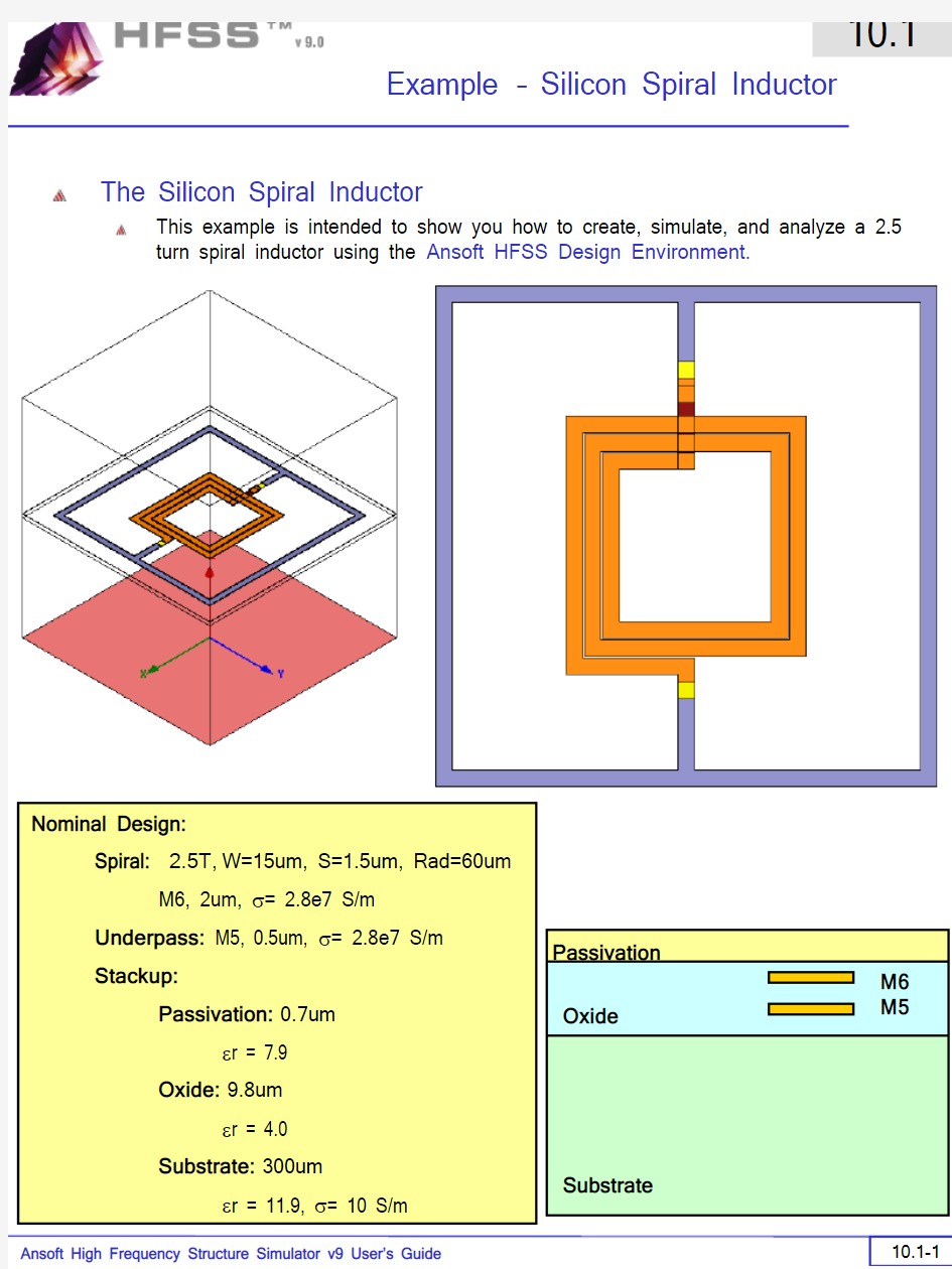
This example is intended to show you how to create, simulate, and analyze a 2.5
turn spiral inductor using the Ansoft HFSS Design Environment.
Substrate
Oxide
Passivation
M6
M5 Nominal Design:
Spiral: 2.5T,W=15um, S=1.5um, Rad=60um
M6, 2um, σ= 2.8e7 S/m
Underpass: M5, 0.5um, σ= 2.8e7 S/m
Stackup:
Passivation: 0.7um
εr = 7.9
Oxide: 9.8um
εr = 4.0
Substrate: 300um
εr = 11.9, σ= 10 S/m
Getting Started
Launching Ansoft HFSS
1.To access Ansoft HFSS, click the Microsoft Start button, select Programs, and
select the Ansoft > HFSS 9 program group. Click HFSS 9.
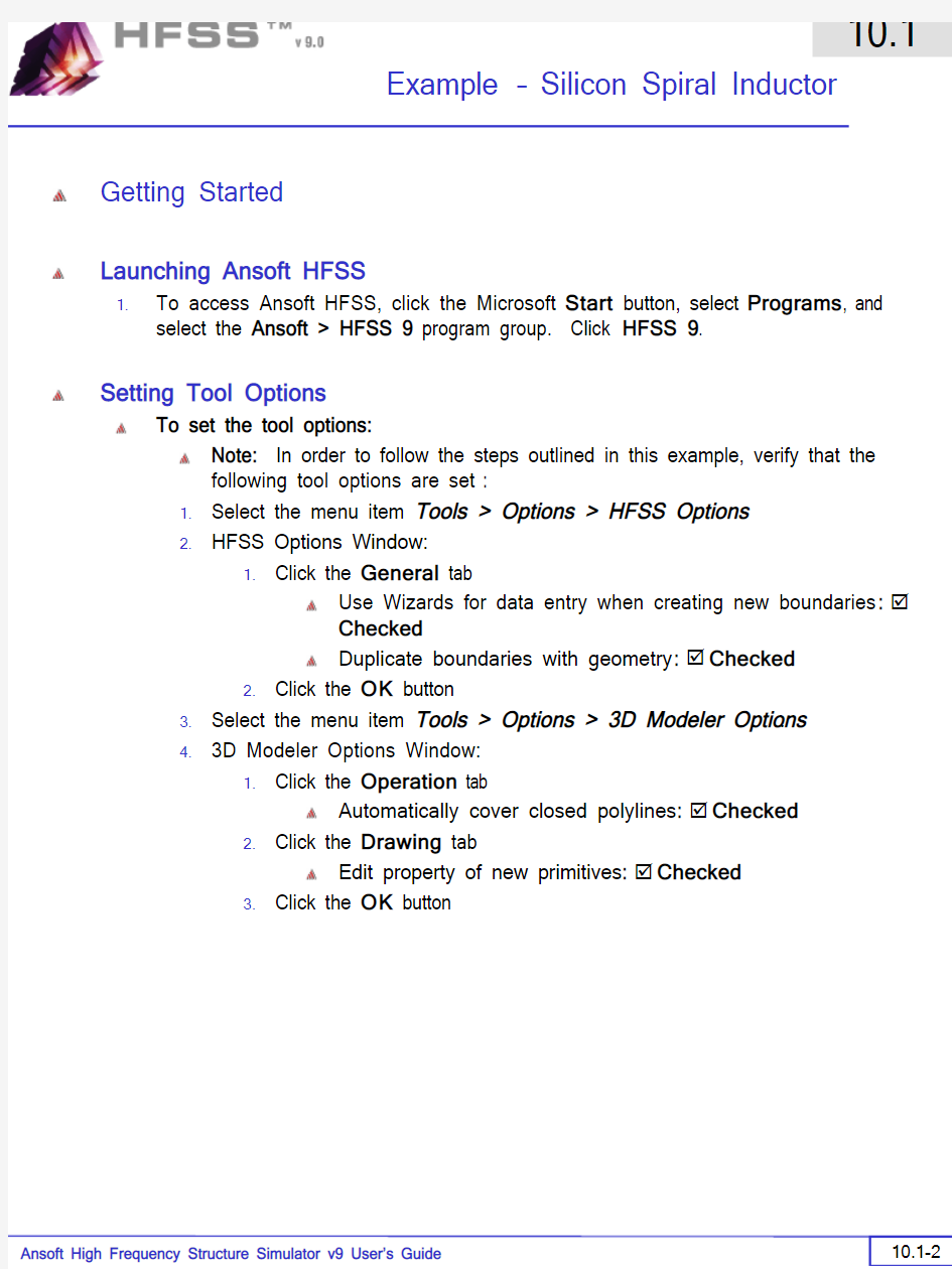
Setting Tool Options
To set the tool options:
Note: In order to follow the steps outlined in this example, verify that the
following tool options are set :
1.Select the menu item Tools > Options > HFSS Options
2.HFSS Options Window:
1.Click the General tab
Use Wizards for data entry when creating new boundaries: ?
Checked
Duplicate boundaries with geometry: ?Checked
2.Click the OK button
3.Select the menu item Tools > Options > 3D Modeler Options.
4.3D Modeler Options Window:
1.Click the Operation tab
Automatically cover closed polylines: ?Checked
2.Click the Drawing tab
Edit property of new primitives: ?Checked
3.Click the OK button
Opening a New Project
To open a new project:
In an Ansoft HFSS window, click the On the Standard toolbar, or select
the menu item File > New.
From the Project menu, select Insert HFSS Design.
Set Solution Type
To set the solution type:
Select the menu item HFSS > Solution Type
Solution Type Window:
Choose Driven Terminal
Click the OK button
Creating the 3D Model
Set Model Units
To set the units:
1.Select the menu item 3D Modeler > Units
2.Set Model Units:
1.Select Units: um
2.Click the OK button
Set Default Material
To set the default material:
https://www.360docs.net/doc/6c5077080.html,ing the 3D Modeler Materials toolbar, choose Select
2.Select Definition Window:
1.Click the Add Material button
2.View/Edit Material Window:
1.For the Material Name type: My_Sub
2.For the Value of Relative Permittivity type: 11.9
3.For the Value of Bulk Conductivity type: 10
4.Click the OK button
3.Click the OK button
Create Substrate
To create the substrate:
1.Select the menu item Draw > Box
https://www.360docs.net/doc/6c5077080.html,ing the coordinate entry fields, enter the box position
X: -270.0, Y: -270.0, Z: 0.0, Press the Enter key
https://www.360docs.net/doc/6c5077080.html,ing the coordinate entry fields, enter the opposite corner of the box:
dX: 540.0, dY: 540.0, dZ: 300.0, Press the Enter key To set the name:
1.Select the Attribute tab from the Properties window.
2.For the Value of Name type: Sub
3.Click the OK button
To fit the view:
1.Select the menu item View > Fit All > Active View.
Set Default Material
To set the default material:
https://www.360docs.net/doc/6c5077080.html,ing the 3D Modeler Materials toolbar, choose Select
2.Select Definition Window:
1.Click the Add Material button
2.View/Edit Material Window:
1.For the Material Name type: My_Oxide
2.For the Value of Relative Permittivity type: 4.0
3.Click the OK button
3.Click the OK button
Create Oxide
To create substrate:
1.Select the menu item Draw > Box
https://www.360docs.net/doc/6c5077080.html,ing the coordinate entry fields, enter the box position
X: -270.0, Y: -270.0, Z: 300.0, Press the Enter key
https://www.360docs.net/doc/6c5077080.html,ing the coordinate entry fields, enter the opposite corner of the box:
dX: 540.0, dY: 540.0, dZ: 9.8, Press the Enter key To set the name:
1.Select the Attribute tab from the Properties window.
2.For the Value of Name type: Oxide
3.Click the OK button
To fit the view:
1.Select the menu item View > Fit All > Active View.
Set Default Material
To set the default material:
https://www.360docs.net/doc/6c5077080.html,ing the 3D Modeler Materials toolbar, choose Select
2.Select Definition Window:
1.Click the Add Material button
2.View/Edit Material Window:
1.For the Material Name type: My_Pass
2.For the Value of Relative Permittivity type: 7.9
3.Click the OK button
3.Click the OK button
Create Passivation
To create substrate:
1.Select the menu item Draw > Box
https://www.360docs.net/doc/6c5077080.html,ing the coordinate entry fields, enter the box position
X: -270.0, Y: -270.0, Z: 309.8, Press the Enter key
https://www.360docs.net/doc/6c5077080.html,ing the coordinate entry fields, enter the opposite corner of the box:
dX: 540.0, dY: 540.0, dZ: 0.7, Press the Enter key To set the name:
1.Select the Attribute tab from the Properties window.
2.For the Value of Name type: Pass
3.Click the OK button
To fit the view:
1.Select the menu item View > Fit All > Active View.
Set Default Material
To set the default material:
https://www.360docs.net/doc/6c5077080.html,ing the 3D Modeler Materials toolbar, choose vacuum
Create Air
To create air:
1.Select the menu item Draw > Box
https://www.360docs.net/doc/6c5077080.html,ing the coordinate entry fields, enter the box position
X: -270.0, Y: -270.0, Z: 0.0, Press the Enter key
https://www.360docs.net/doc/6c5077080.html,ing the coordinate entry fields, enter the opposite corner of the box:
dX: 540.0, dY: 540.0, dZ: 600.0, Press the Enter key To set the name:
1.Select the Attribute tab from the Properties window.
2.For the Value of Name type: Air
3.Click the OK button
To fit the view:
1.Select the menu item View > Fit All > Active View.
Create Radiation Boundary
To select the object Air:
Select the menu item Edit > Select > By Name
Select Object Dialog,
Select the objects named: Air
Click the OK button
To create a radiation boundary
Select the menu item HFSS > Boundaries > Assign > Radiation
Radiation Boundary Window
Name: Rad1
Click the OK button
Create Ground
To create ground:
Select the menu item Draw > Rectangle
Using the coordinate entry fields, enter the box position
X: -270.0, Y: -270.0, Z: 0.0, Press the Enter key
Using the coordinate entry fields, enter the opposite corner of the base
rectangle:
dX: 540.0, dY: 540.0, dZ: 0.0, Press the Enter key To set the name:
Select the Attribute tab from the Properties window.
For the Value of Name type: Ground
Click the OK button
To fit the view:
Select the menu item View > Fit All > Active View.
Assign a Perfect E boundary to the Ground
To select the ground:
1.Select the menu item Edit > Select > By Name
2.Select Object Dialog,
1.Select the objects named: Ground
2.Click the OK button
To assign the Perfect E boundary
1.Select the menu item HFSS > Boundaries > Assign > Perfect E
2.Perfect E Boundary window
https://www.360docs.net/doc/6c5077080.html,: PerfE_Ground
2.Click the OK button
Hide Dielectrics
To hide the dielectrics:
1.Select the menu item Edit > Select All Visible
2.Select the menu item View > Hide Selection > All Views
Set Default Material
To set the default material:
https://www.360docs.net/doc/6c5077080.html,ing the 3D Modeler Materials toolbar, choose Select
2.Select Definition Window:
1.Click the Add Material button
2.View/Edit Material Window:
1.For the Material Name type: My_Met
2.For the Value of Bulk Conductivity type: 2.8e7
3.Click the OK button
3.Click the OK button
Create Offset Coordinate System
To create an offset Coordinate System:
1.Select the menu item 3D Modeler > Coordinate System > Create >
Relative CS > Offset
https://www.360docs.net/doc/6c5077080.html,ing the coordinate entry fields, enter the origin
X: 0.0, Y: 0.0, Z: 304.8,Press the Enter key
Create Spiral Path
To create the path:
1.Select the menu item Draw > Line
https://www.360docs.net/doc/6c5077080.html,ing the coordinate entry fields, enter the vertex point:
X: -60.0, Y: 7.5, Z: 0.0, Press the Enter key
https://www.360docs.net/doc/6c5077080.html,ing the coordinate entry fields, enter the vertex point:
X: -60.0, Y: -60.0, Z: 0.0, Press the Enter key
https://www.360docs.net/doc/6c5077080.html,ing the coordinate entry fields, enter the vertex point:
X: 76.5, Y: -60.0, Z: 0.0,Press the Enter key
https://www.360docs.net/doc/6c5077080.html,ing the coordinate entry fields, enter the vertex point:
X: 76.5, Y: 76.5, Z: 0.0,Press the Enter key
https://www.360docs.net/doc/6c5077080.html,ing the coordinate entry fields, enter the vertex point:
X: -76.5, Y: 76.5, Z: 0.0,Press the Enter key
https://www.360docs.net/doc/6c5077080.html,ing the coordinate entry fields, enter the vertex point:
X: -76.5, Y: -76.5, Z: 0.0,Press the Enter key
https://www.360docs.net/doc/6c5077080.html,ing the coordinate entry fields, enter the vertex point:
X: 93.0, Y: -76.5, Z: 0.0,Press the Enter key
https://www.360docs.net/doc/6c5077080.html,ing the coordinate entry fields, enter the vertex point:
X: 93.0, Y: 93.0, Z: 0.0,Press the Enter key
https://www.360docs.net/doc/6c5077080.html,ing the coordinate entry fields, enter the vertex point:
X: -93.0, Y: 93.0, Z: 0.0,Press the Enter key
https://www.360docs.net/doc/6c5077080.html,ing the coordinate entry fields, enter the vertex point:
X: -93.0, Y: -93.0, Z: 0.0,Press the Enter key
https://www.360docs.net/doc/6c5077080.html,ing the coordinate entry fields, enter the vertex point:
X: 109.5, Y: -93.0, Z: 0.0,Press the Enter key
https://www.360docs.net/doc/6c5077080.html,ing the coordinate entry fields, enter the vertex point:
X: 109.5, Y: 7.5, Z: 0.0,Press the Enter key
https://www.360docs.net/doc/6c5077080.html,ing the coordinate entry fields, enter the vertex point:
X: 131.0, Y: 7.5, Z: 0.0,Press the Enter key
https://www.360docs.net/doc/6c5077080.html,ing the mouse, right-click and select Done
16.Click the OK button when the Properties dialog appears
Create the Spiral
To set the grid plane:
1.Select the menu item 3D Modeler > Grid Plane > XZ
To create conductor profile:
1.Select the menu item Draw > Rectangle
https://www.360docs.net/doc/6c5077080.html,ing the coordinate entry fields, enter the box position
X: -60.0, Y: 7.5, Z: 0.0, Press the Enter key
https://www.360docs.net/doc/6c5077080.html,ing the coordinate entry fields, enter the opposite corner of the base
rectangle:
dX: -15.0, dY: 0.0, dZ: 2.0, Press the Enter key
To set the name:
1.Select the Attribute tab from the Properties window.
2.For the Value of Name type: Spiral
3.Click the OK button
To Sweep the profile:
1.Select the menu item Edit > Select > By Name
2.Select Object Dialog,
1.Select the objects named: Polyline1, Spiral
2.Click the OK button
Note: You can also select the object from the Model Tree
1.Select the menu item Draw > Sweep > Along Path
2.Click the OK button when the Sweep along path dialog appears
To fit the view:
1.Select the menu item View > Fit All > Active View.
Set Grid Plane
To set the grid plane:
1.Select the menu item 3D Modeler > Grid Plane > XY
Create Underpass
To create underpass:
1.Select the menu item Draw > Box
https://www.360docs.net/doc/6c5077080.html,ing the coordinate entry fields, enter the box position
X: -60.0, Y: 7.5, Z: -0.8, Press the Enter key
https://www.360docs.net/doc/6c5077080.html,ing the coordinate entry fields, enter the opposite corner of the box:
dX: -75.0, dY: -15.0, dZ: -0.5, Press the Enter key To set the name:
1.Select the Attribute tab from the Properties window.
2.For the Value of Name type: Underpass
3.Click the OK button
To fit the view:
1.Select the menu item View > Fit All > Active View.
Create Via1
To create via:
1.Select the menu item Draw > Box
https://www.360docs.net/doc/6c5077080.html,ing the coordinate entry fields, enter the box position
X: -60.0, Y: 7.5, Z: 0.0, Press the Enter key
https://www.360docs.net/doc/6c5077080.html,ing the coordinate entry fields, enter the opposite corner of the box:
dX: -15.0, dY: -15.0, dZ: -0.8, Press the Enter key To set the name:
1.Select the Attribute tab from the Properties window.
2.For the Value of Name type: Via1
3.Click the OK button
To fit the view:
1.Select the menu item View > Fit All > Active View.
Create Via2
To create via:
1.Select the menu item Draw > Box
https://www.360docs.net/doc/6c5077080.html,ing the coordinate entry fields, enter the box position
X: -120.0, Y: 7.5, Z: 0.0, Press the Enter key
https://www.360docs.net/doc/6c5077080.html,ing the coordinate entry fields, enter the opposite corner of the box:
dX: -15.0, dY: -15.0, dZ: -0.8, Press the Enter key To set the name:
1.Select the Attribute tab from the Properties window.
2.For the Value of Name type: Via2
3.Click the OK button
To fit the view:
1.Select the menu item View > Fit All > Active View.
Create Feed
To create feed:
1.Select the menu item Draw > Box
https://www.360docs.net/doc/6c5077080.html,ing the coordinate entry fields, enter the box position
X: -120.0, Y: 7.5, Z: 0.0, Press the Enter key
https://www.360docs.net/doc/6c5077080.html,ing the coordinate entry fields, enter the opposite corner of the box:
dX: -22.0, dY: -15.0, dZ: 2.0, Press the Enter key
To set the name:
1.Select the Attribute tab from the Properties window.
2.For the Value of Name type: Feed
3.Click the OK button
To fit the view:
1.Select the menu item View > Fit All > Active View.
Solve Inside Conductors
To solve inside:
1.Select the menu item Edit > Select All Visible
2.Select the menu item Edit > Properties
3.Properties Dialog
1.Solve Inside:?Checked
2.Click the OK button
Click the OK button for all warning messages (Solving inside a solid with high conductivity may require a large mesh)
Seed Mesh Conductors set for Solve Inside
To solve inside:
1.Select the menu item Edit > Select All Visible
2.Select the menu item HFSS > Mesh Operations > Assign > Inside
Selection > Length Based
3.Element Length Based Refinement Dialog
1.Restrict Length of Elements: ? Unchecked
2.Restrict Number of Elements:?Checked
3.Maximum Number of Elements: 5000
4.Click the OK button
Set Default Material
To set the default material:
https://www.360docs.net/doc/6c5077080.html,ing the 3D Modeler Materials toolbar, choose Select
2.Select Definition Window:
1.Type pec in the Search by Name field
2.Click the OK button
Create Ground Ring
To create outer ring:
1.Select the menu item Draw > Box
https://www.360docs.net/doc/6c5077080.html,ing the coordinate entry fields, enter the box position
X: -225.0, Y: -225.0, Z: 0.0, Press the Enter key
https://www.360docs.net/doc/6c5077080.html,ing the coordinate entry fields, enter the opposite corner of the box:
dX: 450.0, dY: 450.0, dZ: 2.0, Press the Enter key To set the name:
1.Select the Attribute tab from the Properties window.
2.For the Value of Name type: Ring
3.Click the OK button
To fit the view:
1.Select the menu item View > Fit All > Active View
Create Inner Ring
To create inner ring:
1.Select the menu item Draw > Box
https://www.360docs.net/doc/6c5077080.html,ing the coordinate entry fields, enter the box position
X: -210.0, Y: -210.0, Z: 0.0, Press the Enter key
https://www.360docs.net/doc/6c5077080.html,ing the coordinate entry fields, enter the opposite corner of the box:
dX: 420.0, dY: 420.0, dZ: 2.0, Press the Enter key To set the name:
1.Select the Attribute tab from the Properties window.
2.For the Value of Name type: Inner
3.Click the OK button
To fit the view:
1.Select the menu item View > Fit All > Active View
Complete the Ring
To select the objects Ring and Male:
1.Select the menu item Edit > Select > By Name
2.Select Object Dialog,
1.Select the objects named: Ring, Inner
2.Click the OK button
To complete the ring:
1.Select the menu item 3D Modeler > Boolean > Subtract
2.Subtract Window
Blank Parts: Ring
Tool Parts: Inner
Click the OK button
Create Extension 1
To create extension:
1.Select the menu item Draw > Box
https://www.360docs.net/doc/6c5077080.html,ing the coordinate entry fields, enter the box position
X: -157.0, Y: 7.5, Z: 0.0, Press the Enter key
https://www.360docs.net/doc/6c5077080.html,ing the coordinate entry fields, enter the opposite corner of the box:
dX: -53.0, dY: -15.0, dZ: 2.0, Press the Enter key To set the name:
1.Select the Attribute tab from the Properties window.
2.For the Value of Name type: Ring_Ext1
3.Click the OK button
To fit the view:
1.Select the menu item View > Fit All > Active View
Create Extension 2
To create extension:
1.Select the menu item Draw > Box
https://www.360docs.net/doc/6c5077080.html,ing the coordinate entry fields, enter the box position
X: 146.0, Y: 7.5, Z: 0.0, Press the Enter key
https://www.360docs.net/doc/6c5077080.html,ing the coordinate entry fields, enter the opposite corner of the box:
dX: 64.0, dY: -15.0, dZ: 2.0, Press the Enter key
To set the name:
1.Select the Attribute tab from the Properties window.
2.For the Value of Name type: Ring_Ext2
3.Click the OK button
To fit the view:
1.Select the menu item View > Fit All > Active View
Group the Conductors
To group the conductors:
1.Select the menu item Edit > Select > By Name
2.Select Object Dialog,
1.Select the objects named: Ring, Ring_Ext1, Ring_Ext2
2.Click the OK button
3.Select the menu item, 3D Modeler > Boolean > Unite
To fit the view:
1.Select the menu item View > Fit All > Active View.
Create Source 1
To create source:
1.Select the menu item Draw > Rectangle
https://www.360docs.net/doc/6c5077080.html,ing the coordinate entry fields, enter the box position
X: -142.0, Y: 7.5, Z: 1.0, Press the Enter key
https://www.360docs.net/doc/6c5077080.html,ing the coordinate entry fields, enter the opposite corner of the base
rectangle:
dX: -15.0, dY: -15.0, dZ: 0.0, Press the Enter key To set the name:
1.Select the Attribute tab from the Properties window.
2.For the Value of Name type: Source1
3.Click the OK button
To fit the view:
1.Select the menu item View > Fit All > Active View.
Assign Excitation
To select the object Source:
1.Select the menu item Edit > Select > By Name
2.Select Object Dialog,
1.Select the objects named: Source1
2.Click the OK button
Note: You can also select the object from the Model Tree To assign lumped port excitation
1.Select the menu item HFSS > Excitations > Assign > Lumped Port
2.Lumped Port : General
https://www.360docs.net/doc/6c5077080.html,: p1,
2.Resistance: 50
3.Reactance: 0
4.Click the Next button
3.Lumped Port : Terminals
1.Number of Terminals: 1,
2.For T1, click the Undefined column and select New Line
https://www.360docs.net/doc/6c5077080.html,ing the coordinate entry fields, enter the vector position
X: -157.0, Y: 0.0, Z: 1.0, Press the Enter key
https://www.360docs.net/doc/6c5077080.html,ing the coordinate entry fields, enter the vertex
dX: 15.0, dY: 0.0, dZ: 0.0, Press the Enter key
5.Click the Finish button
Create Source 2
To create source:
1.Select the menu item Draw > Rectangle
https://www.360docs.net/doc/6c5077080.html,ing the coordinate entry fields, enter the box position
X: 131.0, Y: 7.5, Z: 1.0, Press the Enter key
https://www.360docs.net/doc/6c5077080.html,ing the coordinate entry fields, enter the opposite corner of the base
rectangle:
dX: 15.0, dY: -15.0, dZ: 0.0, Press the Enter key
To set the name:
1.Select the Attribute tab from the Properties window.
2.For the Value of Name type: Source2
3.Click the OK button
To fit the view:
1.Select the menu item View > Fit All > Active View.
Assign Excitation
To select the object Source:
1.Select the menu item Edit > Select > By Name
2.Select Object Dialog,
1.Select the objects named: Source2
2.Click the OK button
Note: You can also select the object from the Model Tree To assign lumped port excitation
1.Select the menu item HFSS > Excitations > Assign > Lumped Port
2.Lumped Port : General
https://www.360docs.net/doc/6c5077080.html,: p2,
2.Resistance: 50
3.Reactance: 0
4.Click the Next button
3.Lumped Port : Terminals
1.Number of Terminals: 1,
2.For T1, click the Undefined column and select New Line
https://www.360docs.net/doc/6c5077080.html,ing the coordinate entry fields, enter the vector position
X: 146.0, Y: 0.0, Z: 1.0, Press the Enter key
https://www.360docs.net/doc/6c5077080.html,ing the coordinate entry fields, enter the vertex
dX: -15.0, dY: 0.0, dZ: 0.0, Press the Enter key
5.Click the Finish button
Show All
To show all object
1.Select the menu item View > Show All > All Views
Boundary Display
To verify the boundary setup:
1.Select the menu item HFSS > Boundary Display(Solver View)
2.From the Solver View of Boundaries, toggle the Visibility check box for the
boundaries you wish to display.
Note: The background (Perfect Conductor) is displayed as the outer
boundary.
Note: The Perfect Conductors are displayed as the smetal boundary.
Note: Select the menu item, View > Visibility to hide all of the
geometry objects. This makes it easier to see the boundary
3.Click the Close button when you are finished
场效应管放大器实验报告
实验六场效应管放大器 一、实验目的 1、了解结型场效应管的性能和特点 2、进一步熟悉放大器动态参数的测试方法 二、实验仪器 1、双踪示波器 2、万用表 3、信号发生器 三、实验原理 实验电路如下图所示:
图6-1 场效应管是一种电压控制型器件。按结构可分为结型和绝缘栅型两种类型。由于场效应管栅源之间处于绝缘或反向偏置,所以输入电阻很高(一般可达上百兆欧)又由于场效应管是一种多数载流子控制器件,因此热稳定性好,抗辐射能力强,噪声系数小。加之制造工艺较简单,便于大规模集成,因此得到越来越广泛的应用。 1、结型场效应管的特性和参数 场效应管的特性主要有输出特性和转移特性。图6-2所示为N 沟道结 图6-2 3DJ6F 的输出特性和转移特性曲线 型场效应管3DJ6F 的输出特性和转移特性曲线。 其直流参数主要有饱和漏极电流I DSS ,夹断电压U P 等;交流参数主要有低频跨导 常数U △U △I g DS GS D m == 表6-1列出了3DJ6F 的典型参数值及测试条件。
表6-1 2、场效应管放大器性能分析 图6-1为结型场效应管组成的共源级放大电路。其静态工作点 2 P GS DSS D )U U (1I I - = 中频电压放大倍数 A V =-g m R L '=-g m R D // R L 输入电阻 R i =R G +R g1 // R g2 输出电阻 R O ≈R D 式中跨导g m 可由特性曲线用作图法求得,或用公式 )U U (1U 2I g P GS P DSS m -- = 计算。但要注意,计算时U GS 要用静态工作点处之数值。 3、输入电阻的测量方法 场效应管放大器的静态工作点、电压放大倍数和输出电阻的测量方法,与实验二中晶体管放大器的测量方法相同。其输入电阻的测量, S D DD g2 g1g1 S G GS R I U R R R U U U -+= -=
场效应管放大电路
第四章场效应管放大电路 本章内容简介 场效应管是利用改变外加电压产生的电场强度来控制其导电能力的半导体器件。它具有双极型三极管的体积小、重量轻、耗电少、寿命长等优点,还具有输入电阻高、热稳定性好、抗辐射能力强、噪声低、制造工艺简单、便于集成等特点。在大规模及超大规模集成电路中得到了广泛的应用。场效应管的分类根据结构和工作原理的不同,场效应管可分为两大类:结型场效应管(JFET)和绝缘栅型场效应管(IGFET)。 4.1 结型场效应管 4.1.1 JFET的结构和工作原理 1. 结构 在一块N型半导体材料的两边各扩散 一个高杂质浓度的P+ 区,就形成两个不对 称的PN结,即耗尽层。把两个P+区并联在 一起,引出一个电极g,称为栅极,在N 型半导体的两端各引出一个电极,分别称 为源极s和漏极d。 场效应管的与三极管的三个电极的对应关系: 栅极g—基极b;源极s—发射极e;漏极d—集电极c夹在两个PN结中间的区域称为导电沟道(简称沟道)。 如果在一块P型半导体的两边各扩散一 个高杂质浓度的N+区,就可以制成一个P沟 道的结型场效应管。P沟道结型场效应管的
结构示意图和它在电路中的代表符号
如图所示。 2. 工作原理 v GS对i D的控制作用 为便于讨论,先假设漏-源极间所加的电压v DS=0。 (a) 当v GS=0时,沟道较宽,其电阻较小。 (b) 当v GS<0,且其大小增加时,在这个反偏电压的作用下,两个PN结耗尽层将加宽。由于N 区掺杂浓度小于P+区,因此,随着|v GS| 的增加,耗尽层将主要向N沟道中扩展,使沟道变窄,沟道电阻增大。当|v GS| 进一步增大到一定值|V P| 时,两侧的耗尽层将在沟道中央合拢,沟道全部被夹断。由于耗尽层中没有载流子,因此这时漏-源极间的电阻将趋于无穷大,即使加上一定的电压v DS,漏极电流i D也将为零。这时的栅-源电压v GS称为夹断电压,用V P表示。在预夹断处:V GD=V GS-V DS =V P 上述分析表明: (a)改变栅源电压v GS的大小,可以有效地控制沟道电阻的大小。 (b)若同时在漏源-极间加上固定的正向电压v DS,则漏极电流i D将受v GS的控制,|v GS|增大时,沟道电阻增大,i D减小。 (c)上述效应也可以看作是栅-源极间的偏置电压在沟道两边建立了电场,电场强度的大小控制了沟道的宽度,即控制了沟道电阻的大小,从而控制了漏极电流i D的大小。 v DS对i D的影响 设v GS值固定,且V P 第三章场效应管放大电路 本章内容简介 场效应管是利用改变外加电压产生的电场强度来控制其导电能力的半导体器件。它具有双极型三极管的体积小、重量轻、耗电少、寿命长等优点,还具有输入电阻高、热稳定性好、抗辐射能力强、噪声低、制造工艺简单、便于集成等特点。在大规模及超大规模集成电路中得到了广泛的应用。场效应管的分类根据结构和工作原理的不同,场效应管可分为两大类:结型场效应管(JFET)和绝缘栅型场效应管(IGFET)。 (一)主要内容: ?结型场效应管的结构及工作原理 ?金属-氧化物-半导体场效应管的结构及工作原理 ?场效应管放大电路的静态及动态性能分析 (二)教学要点: ?了解结型场效应管和MOS管的工作原理、特性曲线及主要参数 ?掌握用公式法和小信号模型分析法分析其放大电路的静态及动态性能 ?了解三极管及场效应管放大电路的特点 (三)基本要求: 介绍结型场效应管和MOS管的工作原理、特性曲线,重点介绍用公式法和小信号模型分析法分析其放大电路静态及动态性能。 3.1 结型场效应管 3.1.1 JFET的结构和工作原理 1. 结构 在一块N型半导体材料的两边各扩散 一个高杂质浓度的P+ 区,就形成两个不对 称的PN结,即耗尽层。把两个P+区并联在 一起,引出一个电极g,称为栅极,在N 型半导体的两端各引出一个电极,分别称 为源极s和漏极d。 场效应管的与三极管的三个电极的对 应关系: 栅极g—基极b;源极s—发射极e;漏极d —集电极c 夹在两个PN结中间的区域称为导电沟道(简称沟道)。 如果在一块P型半导体的两边各扩散一 个高杂质浓度的N+区,就可以制成一个P沟 道的结型场效应管。P沟道结型场效应管的 结构示意图和它在电路中的代表符号 如图所示。 2. 工作原理 v GS对i D的控制作用 为便于讨论,先假设漏-源极间所加的电压v DS=0。 (a) 当v GS=0时,沟道较宽,其电阻较小。 (b) 当v GS<0,且其大小增加时,在这个反偏电压的作用下,两个PN结耗尽层将加宽。由于N区掺杂浓度小于P+区,因此,随着|v GS| 的增加,耗尽层将主要向N沟道中扩展,使沟道变窄,沟道电阻增大。当|v GS| 进一步增大到一定值|V P| 时,两侧的耗尽层将在沟道中央合拢,沟道全部被夹断。由于耗尽层中没有载流子,因此这时漏-源极间的电阻将趋于无穷大,即使加上一定的电压v DS,漏极电流i D也将为零。这时的栅-源电压v GS称为夹断电压,用V P表示。在预夹断处:V GD=V GS -V DS =V P 上述分析表明: (a)改变栅源电压v GS的大小,可以有效地控制沟道电阻的大小。 * 课程设计报告题目:场效应管放大电路设计 学生姓名:学生学号: *** ******** 系专届别: 业: 别: 电气信息工程院 通信工程 2014届 指导教师:** 电气信息工程学院制 2013年3月 **师范学院电气信息工程学院2014届通信工程专业课程设计报告 场效应管放大电路设计 学生:** 指导教师:** 电气信息工程学院通信工程专业 1、课程设计任务和要求: 1.1 1.2 1.3场效应管电路模型、工作点、参数调整、行为特征观察方法研究场效应放大电路的放大特性及元件参数的计算 进一步熟悉放大器性能指标的测量方法 2、课程设计的研究基础: 2.1场效应管的特点 场效应管与双极型晶体管比较有如下特点: (1)场效应管为电压控制型元件; (2)输入阻抗高(尤其是MOS场效应管); (3)噪声系数小; (4)温度稳定性好,抗辐射能力强; (5)结型管的源极(S)和漏极(D)可以互换使用,但切勿将栅(G)源(S)极电压的极性接反,以免P N结因正偏过流而烧坏。对于耗尽型MOS管,其栅源偏压可正可负,使用较灵活。 场效应晶体管(Field Effect Transistor缩写(FET))简称场效应管。场效应管,FET是一种电压控制电流器件。其特点是输入电阻高,噪声系数低,受温度和辐射影响小。因而特别使用于高灵敏度、低噪声电路中。场效应管的种类很多,按结构可 分为两大类:结型场效应管、JFET和绝缘栅型场效应管IGFET。结型场效应管又分为N沟道和P沟道两种。绝缘栅场效应管主要指金属一氧化物—半导体M OS场效应管。MOS管又分为“耗尽型”和“增强型”两种,而每一种又分为N沟道和P沟道。结型场效应管是利用导电沟道之间耗尽区的宽窄来控制电流的输入电阻105---1015之间,绝缘栅型是利感应电荷的多少来控制导点沟道的宽窄从而控制电流的大小、其输入 阻抗很高(其栅极与其他电极互相绝缘)以及它在硅片上的集成度高,因此在大规模 集成电路中占有极其重要的地位。由多数载流子参与导电,也称为单机型晶体管。 场效应管放大电路 一、选择填空(只填①、②…字样) 1.晶体管是依靠 ⑤ 导电来工作的 ⑦ 器件;场效应管是依靠 ① 导电来工作的 ⑥ 器件(①多数载流子,②少数载流子,③电子,④空穴,⑤多数载流子和少数载流子,⑥单极型,⑦双极型,⑧无极型)。 2.晶体管是 ② ;场效应管是 ① (①电压控制器件;②电流控制器件) 3.晶体管的输入电阻比场效应管的输入电阻 ③ (①大得多;②差不多;③小得多)。 4.晶体管的集电极电流 ② ;场效应管的漏极电流 ① (①穿过一个PN 结,② 穿过两个PN 结,③不穿过PN 结) 5.放大电路中的晶体管应工作在 ② ;场效应管应工作在 ① (①饱和区,②放大区,③截止区,④夹断区,⑤可变电阻区)。 6.绝缘栅型场效应管是利用改变 栅源两极 的大小来改变 沟道电阻 的大小,从而 达到控制 漏极电流 的目的;根据 栅源两极电压为零 时,有无 漏极电流 的差别,MOS 管可分为 耗尽 型和 增强 型两种类型。 7.NMOS 管最大的优点是 输入电阻较大 ;其栅—源电压的极性 为负 ,漏—源电压的极性 为正 ;对于增强型NMOS 管,这两种电压的极性 为正 ,对增强型PMOS 管这两种电压的极性为 负 。 8.耗尽型场效应管在恒流区的转移特性方程为()D GS DS i f u u ==常数,它们都是反映 栅源两端电 压 对 漏极电流 控制特性的。 9、当场效应管的漏极直流电流I D 从2mA 变为4mA 时,它的低频跨导g m 将 。 A.增大 B.不变 C.减小 答案:A 二、解答题 2.已知场效应管的输出特性曲线如图P1.22所示,画出它在恒流区的转移特性曲线。 图P1.22 解:在场效应管的恒流区作横坐标的垂线〔如解图P1.22(a )所示〕,读出其与各条曲线交点的纵坐标值及U GS 值,建立i D =f (u GS )坐标系,描点,连线,即可得到转移特性曲线,如解图P1.22(b )所示。 第四章 场效应管(FET )及基本放大电路 §4.1 知识点归纳 一、场效应管(FET )原理 ·FET 分别为JFET 和MOSFET 两大类。每类都有两种沟道类型,而MOSFET 又分为增强型和耗尽型(JFET 属耗尽型),故共有6种类型FET (图4-1)。 ·JFET 和MOSFET 内部结构有较大差别,但内部的沟道电流都是多子漂移电流。一般情况下,该电流与GS v 、DS v 都有关。 ·沟道未夹断时,FET 的D-S 口等效为一个压控电阻(GS v 控制电阻的大小),沟道全夹断时,沟道电流D i 为零;沟道在靠近漏端局部断时称部分夹断,此时D i 主要受控于GS v ,而DS v 影响较小。这就是FET 放大偏置状态;部分夹断与未夹断的临界点为预夹断。 ·在预夹断点,GS v 与DS v 满足预夹断方程: 耗尽型FET 的预夹断方程:P GS DS V v v -=(P V ——夹断电压) 增强型FET 的预夹断方程:T GS DS V v v -=(T V ——开启电压) ·各种类型的FET ,偏置在放大区(沟道部分夹断)的条件由表4-4总结。 表4-4 FET 放大偏置时GS v 与DS v 应满足的关系 ·偏置在放大区的FET ,GS v ~D i 满足平方律关系: 耗尽型: 2 ) 1(P GS DSS D V v I i - =(DSS I ——零偏饱和漏电流) 增强型:2 )(T GS D V v k i -=* · FET 输出特性曲线反映关系 参变量 G S V DS D v f i )(=,该曲线将伏安平面分为可变电阻区 (沟道未夹断),放大区(沟道部分夹断)和截止区(沟道全夹断);FET 转移特性曲线反映在放大区的关系)(GS D v f i =(此时参变量DS V 影响很小),图4-17画出以漏极流向源极的沟道电流为参考方向的6种FET 的转移特性曲线,这组曲线对表4-4是一个很好映证。 二、FET 放大偏置电路 ·源极自给偏压电路(图4-18)。该电路仅适用于耗尽型FET 。有一定稳Q 的能力,求解该电路工作点的方法是解方程组: 22() [FET ()]GS D DSS d GS T P GS S D v i I v i k v V V v R i ? =-=-?? ?=-?对于增强型,用关系式 ·混合偏压电路(图4-20)。该电路能用于任何FET ,在兼顾较大的工作电流时,稳Q 的效果更好。求解该电路工作点的方法是解方程组: ??? ??-+=D s CC GS i R R R R V v 212平方律关系式 以上两个偏置电路都不可能使FET 全夹断,故应舍去方程解中使沟道全夹断的根。 三、FET 小信号参数及模型 ·迭加在放大偏置工作点上的小信号间关系满足一个近似的线性模型(图4-22低频模 型,图4-23高频模型)。 ·小信号模型中的跨导 Q GS D m v i g ??= m g 反映信号gs v 对信号电流d i 的控制。m g 等于FET 转移特性曲线上Q 点的斜率。 m g 的估算:耗尽管 D DSS P m I I V g ||2 = 增强管D m kI g 2= ·小信号模型中的漏极内阻 Ds ds D Q v r i ?= ? ds r 是FET “沟道长度调效应”的反映,ds r 等于FET 输出特性曲线Q 点处的斜率的倒 数。 四、基本组态FET 小信号放大器指标 1.基本知识 ·FET 有共源(CS )共漏(CD )和共栅(CG )三组放大组态。 3. 场效应管及其放大电路 (文字材料) 本章概要 本章首先介绍结型场效应管和绝缘栅型场效应管的结构、放大原理、伏安特性以及主要电参数,然后讨论了场效应管的微变等效电路,分析了场效应管和晶体管的特点,并讨论了场效应管组成的共源极、共漏极和共栅极三种基本放大电路的工作原理、特性分析及参数计算。 本章内容的组成及结构 结型场效应管 绝缘栅型场效应管 结构、类型(N 沟道、P 沟道)、符号 结型 工作原理 伏安特性、主要参数 按工作方式:增强型、耗尽型 按导电沟道:N 沟道、P 沟道 工作原理 伏安特性、主要参数 场效应管的小信号模型(微变等效电路) 场效应管与晶体管的比较 场效应管的偏置及静态分析 共源极放大电路 三种基本放大电路的动态分析 共漏极放大电路 共栅极放大电路 学习目标 (1)熟练掌握场效应管的伏安特性; (2)熟练掌握场效应管的微变等效电路; (3)熟练掌握场效应管组成的三种基本放大电路的组成、工作原理及静态和动态分析; (4)了解三种放大电路的各自特点及应用场合; (5)了解场效应管与双极型三极管的异同点。 重难点指导 重点: (1)结型及MOS 型场效应管的工作原理及伏安特性; 场效应管 及 其放 大 电路 类型 绝缘栅型 结构、类型 场效应管基本放大电路 场效应管 (FET ) (2)共源极和共漏极放大电路的静态及动态参数计算; 难点: (1)场效应管跨导的概念以及微变等效电路; (2)场效应管放大电路的静态与动态主要指标计算。 本章导学 1. 场效应管 1.场效应管(FET)有结型场效应管(JFET)和绝缘栅型场效应管(IGFET)两大类型。它们都有N沟道和P沟道两类。IGFET又分为增强型和耗尽型;JFET只有耗尽型。IGFET大多制成金属—氧化物—半导体结构,简称为MOSFET。 2.场效应管与半导体三极管的区别 1.半导体三极管(晶体管)是一种电流控制器件,有两种载流子参与导电,属于双极型器件,因此又常称半导体三极管为双极型晶体管;场效应管只靠一种载流子(多数载流子)导电,属于单极型器件,因此又常称场效应管为单极型晶体管,它是一种电压控制器件,i G≈0,具有输入电阻高的特点。 3.场效应管的工作原理 a.控制漏极电流的基本原理:通过控制电压的变化改变场效应管导电沟道的宽度,以改变其电阻的大小来控制漏极电流。 b.JFET和MOSFET在控制漏极电流方式上的区别:JFET通过控制电压的变化改变耗尽层的宽度来控制漏极电流;MOSFET利用半导体表面的电场效应,直接改变作为导电沟道的反型层宽度,以达到控制漏极电流的目的。 4.场效应管的伏安特性 由于FET的i G≈0,所以只给出输出特性和由它派生的转移特性。各类FET的输出特性曲线如表3.1中所示。 a.输出特性i D = f (u DS) | u GS一定由输出特性曲线可见,FET有三个工作区: 可变电阻区——沟道尚未出现予夹断,管子可看作是一个由电压控制的可变电阻。在不同的u GS下,曲线上升的斜率不同,电阻值也不同。 恒流区——沟道出现予夹断,i D只受u GS控制,几乎不随u DS的改变而变化,输出特性曲线几乎成为水平的直线。恒流区又称饱和区或放大区。 夹断区——管子处于沟道完全夹断的情况,i D≈0,夹断区也称为截止区。 b.转移特性:i D = f (u GS) | u DS一定它描述了场效应管的u GS对i D的控制能力。 5.场效应管的主要参数 a.直流参数:开启电压U GS(th)(适用于增强型MOSFET);夹断电压U GS(off)、零偏漏极电流I DSS(适用于耗尽型FET)。 b.交流参数:极间电容C gs、C ds、C gd;跨导g m(也称互导),它是管子在保持U DS一定时,漏极电流微变量d i D与栅源极间电压微变量d u GS的比值,即: 场效应管基本放大电路 1.场效应管放大器偏置电路与直流分析 场效应管和品休三极管一样,也可以构成三种基本纽态:共源、共栅、共 漏放大器。在放大电路中,场效应管工作在饱和区,所以必须给场效应管加 上一定的直流他置。下面以N沟道结型场效应管为例进行为论。 (1)自偏压共源放大电路共源放大电路如图3—5所示。其直流通路 如图3—6所示。 只为源极电阻,Rg为栅极电阻,提供直流通路,Rd为漏极电阻。由于场 效应管栅极电流为零,所以加钽电容在栅源极间的电压是由电阻R上压降通过只g 提供的,这种形式的偏置电路称为自偏压偏置电路。 根据电路写出方程 (2)分压式自偏压共源放大电路分压式自偏压共源放大电路如图 所示。其直流通路如图3—8所示。 共源、共栅和共希迪电子漏放大器分别与共射、共基和共集放大器相对应。归纳起来,主要有以下特点: ①共源、共栅放大器的放大倍数较大,共漏放大器的放大倍数小于l但 接近于1,可作为跟随器使用,而共源放大器输出电压和输入电压反相; ②共栅放大器的输入电阻最小; ③共漏放大器的输出电阻最小。cjmc%ddz 真正好的朋友,从来不需要这些表面功夫。走在这漫漫俗尘,形如微尘的我们,每天忙碌的像只蝼蚁,哪有时间去整那些虚假的表面文章。那些沉淀在岁月里的真情实意,哪一个不是无事各自忙,有事时,却又从不问回报几何的真心相助? 至于那些平日里看上去可以一起打闹,一起吃喝,一起厮混,看似好成一片的人,或许,只是你在多少次的四目相对之时,动了真心,存了真义,是你默默认定对方可称朋友,有困难的时候是你愿意伸以援手,但未必对方一样。 多少看似热情的人,内心是薄情的。而多少看似淡漠的人,内心实则一片温热。那些表面热诚的人,总是相安无事各自好,一旦你有事需要援助,别说大事,就是小事需代劳,你都会发现原来不过情比纸薄,对方远比你自己想的要现实的多。 有些人,自从与你接近,内心就存有一份自己的打算。定是你于他而言,多少有些可用之处。正所谓无事献殷勤,非奸即盗。在这个功利心弥漫的世态下,没有哪一份意外的热情不无所图。不仅是职场如此,男人如此,就连女人也不能免俗。 接孩子的时候,被困高层电梯下不来,一个电话打来,希望能帮忙照看一下放学的孩子。实在的人总是把别人毫不见外的信任,当作是一种荣幸,于是想都不用想就能一口答应。可当你有事需要对方只是代笔签个字这样的举手之劳时,对方都能各种不情愿各种推脱,至此你终是发现,原来人与人之间真不是一杯换一盏的事儿。关键时刻,还是得找那些看似平时不联系,但一开口能力范围之内就愿意为你想办法的人。 多少人天真的以为,认识的人越多,人脉就越广,自己就越厉害,其实,那些所谓的人脉,不过廉价。倘若你没有同等的利用价值,谁会与你建立起所谓的交际?最是谈钱伤感情,也最是感情不值钱。别结识了比自己优秀比自己有能力的人,就觉得有了依靠有了光环,自己不足够优秀,结识谁都没有用。在你困难需求的时候,你开口求助,能够推脱敷衍那算给面子,对你闭门不见佯装不熟也是情理之中。 日久见人心,患难见真情。平时是平时,别把平时当真情。这世上多少人变脸如翻书,有求于你一个样,各自安好一个样,最是有求于他嘴脸陋,让你瞬间就明白,何谓人情凉薄。 随着年龄的增长,人心的不再纯澈,人与人之间的交往就不再那么的纯粹而真心了。也正是因为如此,才更要珍惜那些默默守护在你生活中的朋友。别看平时忙的少有见面,少有聊天,就连微信,都少有私信。但有事儿的时候,只一声招呼,谁能出力都会挺身而出,义不容辞。 真正好的朋友,从来不需要这些表面功夫。走在这漫漫俗尘,形如微尘的我们,每天忙碌的像只蝼蚁,哪有时间去整那些虚假的表面文章。那些沉淀在岁月里的真情实意,哪一个不是无事各自忙,有事时,却又从不问回报几何的真心相助? 至于那些平日里看上去可以一起打闹,一起吃喝,一起厮混,看似好成一片的人,或许,只是你在多少次的四目相对之时,动了真心,存了真义,是你默默认定对方可称朋友,有困难的时候是你愿意伸以援手,但未必对方一样。 多少看似热情的人,内心是薄情的。而多少看似淡漠的人,内心实则一片温热。那些表面热诚的人,总是相安无事各自好,一旦你有事需要援助,别说大事,就是小事需代劳,你都会发现原来不过情比纸薄,对方远比你自己想的要现实的多。 有些人,自从与你接近,内心就存有一份自己的打算。定是你于他而言,多少有些可用之处。正所谓无事献殷勤,非奸即盗。在这个功利心弥漫的世态下,没有哪一份意外的热情不无所图。不仅是职场如此,男人如此,就连女人也不能免俗。 接孩子的时候,被困高层电梯下不来,一个电话打来,希望能帮忙照看一下放学的孩子。实在的人总是把别人毫不见外的信任,当作是一种荣幸,于是想都不用想就能一口答应。可当你有事需要对方只是代笔签个字这样的举手之劳时,对方都能各种不情愿各种推脱,至此你终是发现,原来人与人之间真不是一杯换一盏的事儿。关键时刻,还是得找那些看似平时不联系,但一开口能力范围之内就愿意为你想办法的人。 多少人天真的以为,认识的人越多,人脉就越广,自己就越厉害,其实,那些所谓的人脉,不过廉价。倘若你没有同等的利用价值,谁会与你建立起所谓的交际?最是谈钱伤感情,也最是感情不值钱。别结识了比自己优秀比自己有能力的人,就觉得有了依靠有了光环,自己不足够优秀,结识谁都没有用。在你困难需求的时候,你开口求助,能够推脱敷衍那算给面子,对你闭门不见佯装不熟也是情理之中。 日久见人心,患难见真情。平时是平时,别把平时当真情。这世上多少人变脸如翻书,有求于你一个样,各自安好一个样,最是有求于他嘴脸陋,让你瞬间就明白,何谓人情凉薄。 随着年龄的增长,人心的不再纯澈,人与人之间的交往就不再那么的纯粹而真心了。也正是因为如此,才更要珍惜那些默默守护在你生活中的朋友。别看平时忙的少有见面,少有聊天,就连微信,都少有私信。但有事儿的时候,只一声招呼,谁能出力都会挺身而出,义不容辞。场效应管放大电路.(DOC)
场效应管放大电路设计
(整理)场效应管放大电路13912
第四章场效应管(FET)及基本放大电路
场效应管及其放大电路
场效应管基本放大电路