SF5930S_DS_final_v1.1

SF5930S
FEATURES
◆Proprietary NC-Cap/PSR-II TM Control:
●±4% CC and CV Precision
●Proprietary “Audio Noise Cancellation”
Control
● Built-in “Fast Dynamic Response” Control to
Meet USB Charge Requirements
● Proprietary “Zero-Output Startup” Control
● Proprietary “Smart Output Short Protection”
●Without External Compensation/Filtering
Capacitor Needed
● Max. 50V Output for AC/DC LED Lighting
◆Proprietary Cable Drop Compensation
◆Multi Mode Control
◆Low Standby Power Under 70mW
◆Wide VDD Operating Range
◆Cycle-by-Cycle Current Limiting
◆Leading Edge Blanking (LEB)
◆Built-in Soft Start
◆Pin Floating Protection
◆VDD Under Voltage Lockout (UVLO)
◆VDD OVP & Clamp
APPLICATIONS
◆Battery chargers for cellular phones, cordless
phones, PDA, digital cameras, etc
◆Replaces linear transformer and RCC SMPS
◆AC/DC LED lighting GENERAL DESCRIPTION
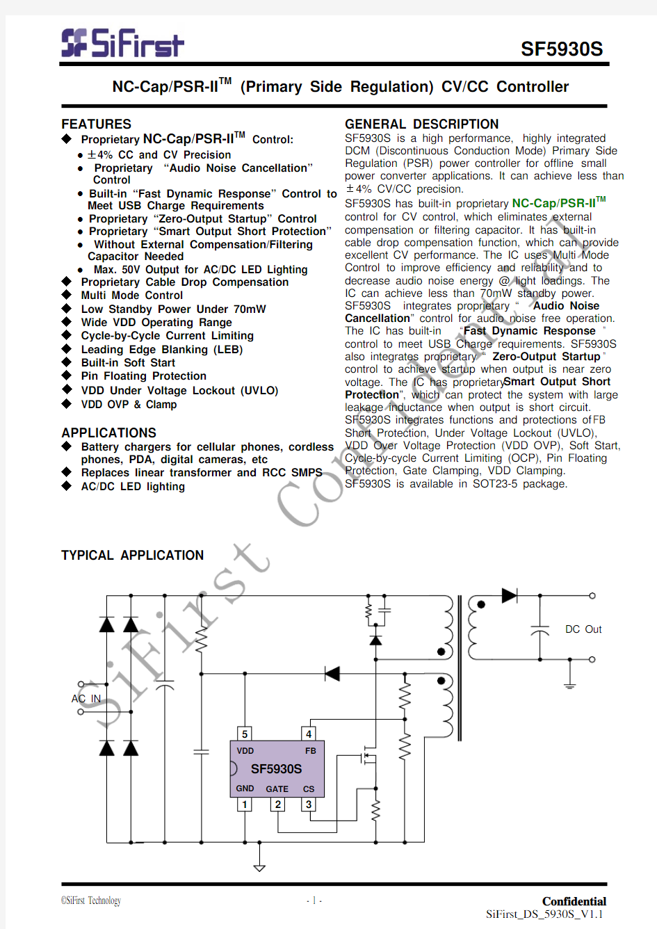
SF5930S is a high performance, highly integrated DCM (Discontinuous Conduction Mode) Primary Side Regulation (PSR) power controller for offline small power converter applications. It can achieve less than ±4% CV/CC precision.
SF5930S has built-in proprietary NC-Cap/PSR-II TM control for CV control, which eliminates external compensation or filtering capacitor. It has built-in cable drop compensation function, which can provide excellent CV performance. The IC uses Multi Mode Control to improve efficiency and reliability and to decrease audio noise energy @ light loadings. The IC can achieve less than 70mW standby power.
SF5930S integrates proprietary “Audio Noise Cancellation” control for audio noise free operation. The IC has built-in “Fast Dynamic Response” control to meet USB Charge requirements. SF5930S also integrates proprietary “Zero-Output Startup” control to achieve startup when output is near zero voltage. The IC has proprietary “Smart Output Short Protection”, which can protect the system with large leakage inductance when output is short circuit.
SF5930S integrates functions and protections of FB Short Protection, Under Voltage Lockout (UVLO), VDD Over Voltage Protection (VDD OVP), Soft Start, Cycle-by-cycle Current Limiting (OCP), Pin Floating Protection, Gate Clamping, VDD Clamping.
SF5930S is available in SOT23-5 package.
NC-Cap/PSR-II TM (Primary Side Regulation) CV/CC Controller
Pin Configuration
Block Diagram
ELECTRICAL CHARACTERISTICS
O
Note 1. Stresses beyond those listed under “Absolute Maximum Ratings” may cause permanent damage to the device. These are stress ratings only, and functional operation of the device at these or any other conditions beyond those indicated in the operational sections of the specifications is not implied.
Exposure to absolute maximum rating conditions for extended periods may affect device reliability. Note 2. The device is not guaranteed to function outside its operating conditions.
CHARACTERIZATION PLOTS
OPERATION DESCRIPTION
SF5930S is a high performance, highly integrated DCM (Discontinuous Conduction Mode) Primary Side Regulation (PSR) controller. The built-in high precision CV/CC control makes it very suitable for offline small power converter applications.
◆ PSR Technology Introduction
Assuming the system works in DCM mode, the power transfer function is given by
ηdem S S
P
pk o T f N N I I ×××
×=
2
η
(Eq.3)
CC (Constant Current) Control Scheme
From Eq.3, it can be easily seen that there are two ways to implement CC control: one is PFM (Pulse Frequency Modulation), the control scheme is to keep Ipk to be constant, let the product of Ts and Tdem (fs*Tdem) to be a constant. In this way, Io
will be a value independent to the variation of Vo, Lm, and line input voltage. Another realization method is PWM duty control, the control scheme is to keep fs to be constant, let the product of Tdem and Ipk (Tdem*Ipk) to be a constant, in another words, by modulating system duty cycle to realize a constant Io independent to the variation of Vo, Lm and line voltages.
SF5930S adopts PFM for CC control, the product of
● Smart Output Short Protection
The output short circuit protection of conventional PSR system is based on the coupling between auxiliary winding and secondary winding. When output is short, the auxiliary winding cannot provide enough energy to the IC any more. In this way, the system will enter into auto-recovery mode protection. However, the IC may be wrongly supplied if the leakage inductance of the primary
winding is large enough.
In SF5930S, if output short circuit occurs, the IC will detect the situation and enter into auto-recovery mode protection.
● Proprietary Zero-Output Startup Control
Conventional PSR system may suffer startup failure when output voltage is near zero voltage, which means that there is a gap between OCP (CC point in PSR CV/CC system) and full loading. Larger
Capacitor Needed
SF5930S uses a proprietary control to eliminate external compensation capacitor, which can simplify system design and lower system cost.
● Maximum 50V Output for LED Lighting
SF5930S can support maximum 50V output, which can be used in AC/DC LED lighting.
◆ Proprietary Cable Drop Compensation
SF5930S has a proprietary built-in cable voltage drop compensation block which can provide a constant output voltage at the end of the cable over the entire load range in CV mode.
◆ Multi Mode PSR Control for High
Reliability , High Efficiency
Conventional pure PFM controlled PSR system may suffer transformer saturation issue when heavy loading. In SF5930S, a proprietary multi mode control is adopted to suppress this issue, as shown in Fig.2. Around the full load, the system operates in PWM+PFM mode, which improve the system reliability. Under normal to light load
conditions, the IC operates in PFM mode to achieve excellent regulation and high efficiency.
◆ Soft Start
SF5930S features an internal 2ms (typical) soft start that slowly increases the threshold of cycle-by-cycle current limiting comparator during startup sequence. Every startup process is followed by a soft start activation.
is
AC line voltage. In SF5930S the IC has built-in blocks to compensate the variation, as shown in Fig3. The IC can adjust CC point based on sensed output voltage and PFM duty. In this way, CC accuracy can be improved.
Fig.3
◆ Auto Recovery Mode Protection
As shown in Fig.4, once a fault condition is detected, switching will stop. This will cause VDD to fall because no power is delivered form the auxiliary winding. When VDD falls to UVLO(off) (typical 9.5V), the protection is reset and the
operating current reduces to the startup current, which causes VDD to rise, as shown in Fig.4. However, if the fault still exists, the system will experience the above mentioned process. If the fault has gone, the system resumes normal operation. In this manner, the auto restart can alternatively enable and disable the switching until
9.5V
19V
Fig.4
◆ VDD OVP(Over Voltage Protection)
VDD OVP is implemented in SF5930S and it is a protection of auto-recovery mode.
◆ Soft Gate Drive
PACKAGE MECHANICAL DATA
IMPORTANT NOTICE
SiFirst Technology Nanhai, Ltd (SiFirst) reserves the right to make corrections, modifications, enhancements, improvements and other changes to its products and services at any time and to discontinue any product or service without notice. Customers should obtain the latest relevant information before placing orders and should verify that such information is current and complete.
SiFirst warrants performance of its hardware products to the specifications applicable at the time of sale in accordance with SiFirst’s standard warranty. Testing and other quality control techniques are used to the extent SiFirst deems necessary to support this warranty. Except where mandated by government requirements, testing of all parameters of each product is not necessarily performed.
SiFirst assumes no liability for application assistance or customer product design. Customers are responsible for their products and applications using SiFirst’s components. To minimize the risks associated with customer products and applications, customers should provide adequate design and operating safeguards. Reproduction of SiFirst’s information in SiFirst’s data books or data sheets is permissible only if reproduction is without alteration and is accompanied by all associated warranties, conditions, limitations, and notices. Reproduction of this information with alteration is an unfair and deceptive business practice. SiFirst is not responsible or liable for such altered documentation. Information of third parties may be subject to additional restrictions.
Resale of SiFirst’s products or services with statements different from or beyond the parameters stated by SiFirst for that product or service voids all express and any implied warranties for the associated SiFirst’s product or service and is an unfair and deceptive business practice. SiFirst is not responsible or liable for any such statements.
SiFirst’s products are neither designed nor intended for use in military applications. SiFirst will not be held liable for any damages or claims resulting from the use of its products in military applications.
SiFirst’s products are not designed to be used as components in devices intended to support or sustain human life. SiFirst will not be held liable for any damages or claims resulting from the use of its products in medical applications.