MAX6852AEE+;MAX6852AEE+T;中文规格书,Datasheet资料
General Description
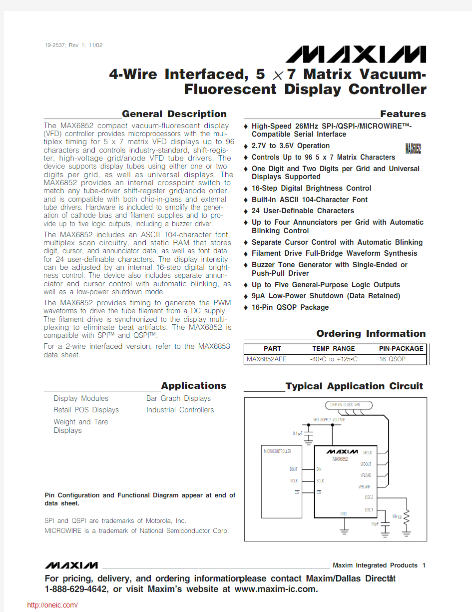
The MAX6852 compact vacuum-fluorescent display (VFD) controller provides microprocessors with the mul-tiplex timing for 5 x 7 matrix VFD displays up to 96characters and controls industry-standard, shift-regis-ter, high-voltage grid/anode VFD tube drivers. The device supports display tubes using either one or two digits per grid, as well as universal displays. The MAX6852 provides an internal crosspoint switch to match any tube-driver shift-register grid/anode order,and is compatible with both chip-in-glass and external tube drivers. Hardware is included to simplify the gener-ation of cathode bias and filament supplies and to pro-vide up to five logic outputs, including a buzzer driver.The MAX6852 includes an ASCII 104-character font,multiplex scan circuitry, and static RAM that stores digit, cursor, and annunciator data, as well as font data for 24 user-definable characters. The display intensity can be adjusted by an internal 16-step digital bright-ness control. The device also includes separate annun-ciator and cursor control with automatic blinking, as well as a low-power shutdown mode.
The MAX6852 provides timing to generate the PWM waveforms to drive the tube filament from a DC supply.The filament drive is synchronized to the display multi-plexing to eliminate beat artifacts. The MAX6852 is compatible with SPI? and QSPI?.
For a 2-wire interfaced version, refer to the MAX6853data sheet.
Applications
Features
o High-Speed 26MHz SPI-/QSPI-/MICROWIRE?-Compatible Serial Interface
o 2.7V to 3.6V Operation
o Controls Up to 96 5 x 7 Matrix Characters o One Digit and Two Digits per Grid and Universal Displays Supported o 16-Step Digital Brightness Control o Built-In ASCII 104-Character Font o 24 User-Definable Characters
o Up to Four Annunciators per Grid with Automatic Blinking Control o Separate Cursor Control with Automatic Blinking o Filament Drive Full-Bridge Waveform Synthesis o Buzzer Tone Generator with Single-Ended or Push-Pull Driver o Up to Five General-Purpose Logic Outputs o 9μA Low-Power Shutdown (Data Retained)o 16-Pin QSOP Package
MAX6852
4-Wire Interfaced, 5 ?7 Matrix Vacuum-Fluorescent Display Controller
________________________________________________________________Maxim Integrated Products 1
Ordering Information
19-2537; Rev 1; 11/02
For pricing, delivery, and ordering information,please contact Maxim/Dallas Direct!at 1-888-629-4642, or visit Maxim’s website at https://www.360docs.net/doc/6b11772867.html,.
Display Modules Retail POS Displays Weight and Tare Displays
Bar Graph Displays Industrial Controllers
SPI and QSPI are trademarks of Motorola, Inc.
MICROWIRE is a trademark of National Semiconductor Corp.
Typical Application Circuit
Pin Configuration and Functional Diagram appear at end of data sheet.
M A X 6852
4-Wire Interfaced, 5 ?7 Matrix Vacuum-Fluorescent Display Controller 2_______________________________________________________________________________________
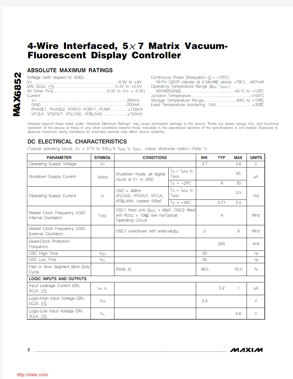
ABSOLUTE MAXIMUM RATINGS
Stresses beyond those listed under “Absolute Maximum Ratings” may cause permanent damage to the device. These are stress ratings only, and functional operation of the device at these or any other conditions beyond those indicated in the operational sections of the specifications is not implied. Exposure to absolute maximum rating conditions for extended periods may affect device reliability.
Voltage (with respect to GND)
V+.............................................................................-0.3V to +4V DIN, SCLK, CS ......................................................-0.3V to +5.5V All Other Pins................................................-0.3V to (V+ + 0.3V)Current
V+..................................................................................200mA GND.............................................................................-200mA PHASE1, PHASE2, PORT0, PORT1, PUMP................±150mA VFCLK, VFDOUT, VFLOAD, VFBLANK......................±150mA
Continuous Power Dissipation (T A = +70°C)
16-Pin QSOP (derate at 8.34mW/°C above +70°C).....667mW Operating Temperature Range (T MIN , T MAX )
MAX6852AEE................................................-40°C to +125°C Junction Temperature......................................................+150°C Storage Temperature Range.............................-65°C to +150°C Lead Temperature (soldering, 10s).................................+300°C
DC ELECTRICAL CHARACTERISTICS
MAX6852
4-Wire Interfaced, 5 ?7 Matrix Vacuum-Fluorescent Display Controller
_______________________________________________________________________________________3
Note 2:Guaranteed by design.
DC ELECTRICAL CHARACTERISTICS (continued)
M A X 6852
4-Wire Interfaced, 5 ?7 Matrix Vacuum-Fluorescent Display Controller 4_______________________________________________________________________________________
Typical Operating Characteristics
(Typical operating circuit, V+ = 3.3V, T A = +25°C, unless otherwise noted.)
SUPPLY CURRENT vs. SUPPLY VOLTAGE
V+ (V)
I S U P P L Y (m A )
3.43.23.12.9
1.61.71.81.9
2.0
2.12.21.5
2.7
3.6 SHUTDOWN SUPPLY CURRENT
vs. SUPPLY VOLTAGE
V+ (V)
I S U P P L Y (μA )
3.53.33.12.95152035
4045500
2.7102530FREQUENCY (MHz)
765432004006008001000
12001400
28
SHUTDOWN SUPPLY CURRENT vs. EXTERNAL OSC FREQUENCY
A X 6852 t o c 03
I S U P P L Y (μA )
80
60
4020
100
OUTPUT LOW VOLTAGE vs. I SINK
I SINK (mA)
V O L (V )
0.20.60.81.4
1.61.8
2.000.41.01.280
60
4020
100
OUTPUT LOW VOLTAGE vs. I SINK
I SINK (mA)
V O L (V )
0.20.60.81.4
1.61.8
2.000.41.01.280
60
4020
100
OUTPUT LOW VOLTAGE vs. I SINK
I SINK (mA)
V O L (V )
0.20.60.81.4
1.61.8
2.0
00.41.01.280
60
40
20
100
V
IN - V OH vs. I SOURCE
I SOURCE (mA)V O L (V )
0.5
1.5
2.0
01.0
80
60
40
20
100
V IN - V
OH vs. I SOURCE
I SOURCE (mA)V O L (V )
0.20.60.81.4
1.61.8
2.00
0.41.01.280
60
40
20
100
V
IN - V OH vs. I SOURCE
I SOURCE (mA)V O L (V )
0.5
1.5
2.0
1.0
MAX6852
4-Wire Interfaced, 5 ?7 Matrix Vacuum-Fluorescent Display Controller
_______________________________________________________________________________________5
f OSC vs. TEMPERATURE
TEMPERATURE (°C)
f O S C (M H z )
1109580655035205-10-250.5
1.0
1.5
2.0
2.5
-40125
DEAD-CLOCK OSC FREQUENCY
vs. TEMPERATURE
TEMPERATURE (°C)
F R E Q U E N C Y (M H z )1109580655035205-10-25-40125
0.02
0.040.060.080.100.120.140.160.18
Typical Operating Characteristics (continued)
(Typical operating circuit, V+ = 3.3V, T A = +25°C, unless otherwise noted.)
Pin Description
M A X 6852
Detailed Description
Overview of the MAX6852
The MAX6852 VFD controller generates the multiplex timing for the following VFD display types:
?Multiplexed displays with one digit per grid, and up to 48 grids (in 48/1 mode). Each grid can contain one 5 x 7 matrix character, a decimal place (DP)segment, a cursor segment, and four extra annunci-ator segments (Figure 1).?Multiplexed displays with two digits per grid, and up to 48 grids (in 96/2 mode). Each grid can contain two 5 x 7 matrix characters, two DP segments, and two cursor segments. No annunciator segments are supported (Figure 2).
Each digit can have a 5 x 7 matrix character, a DP seg-ment, a cursor segment, and (for one-digit-per-grid dis-plays only) four annunciators (Figure 3).
The 5 x 7 matrix character segments are not controlled directly, but use on-chip fonts that map the segments.
The fonts comprise an ASCII 104-character fixed-font set, and 24 user-definable characters. The predefined characters follow the Arial font, with the addition of the following common symbols: £, €, ¥, °, μ, ±, ↑, and ↓.The 24 user-definable characters are uploaded by the user into on-chip RAM through the serial interface and are lost when the device is powered down. As well as custom 5 x 7 characters, the user-definable fonts can control up to 35 custom segments, bar graphs, or graphics.
Annunciator segments have individual, independent control, so any combination of annunciators can be lit.Annunciators can be off, lit, or blink either in phase or out of phase with the cursor. The blink-speed control is software selectable to be one or two blinks per second (OSC = 4MHz).
DP segments can be lit or off, but have no blink control.A DP segment is set by the same command that writes the digit ’s 5 x 7 matrix character.
4-Wire Interfaced, 5 ?7 Matrix Vacuum-Fluorescent Display Controller 6
_______________________________________________________________________________________
Figure 1. Example of a One-Digit-per-Grid Display
The cursor segment is controlled differently. A single register selects one digit ’s cursor from the entire dis-play, and that can be lit either continuously or blinking.All the other digits ’ cursors are off.
The designations of DP, cursor, and annunciator are interchangeable. For example, consider an application requiring only one DP lit at a time, but the DP needs to blink. The DP function does not have blink capability.Instead, the DP segments on the display are routed (using the output map) to the cursor function. In this case, the DP segments are controlled using the cursor register.
The output of the controller is a 4-wire serial stream that interfaces to industry-standard, shift-register, high-volt-age grid/anode VFD tube drivers (Figure 4). This inter-face uses three outputs to transfer and latch grid and anode data into the tube drivers, and a fourth output that enables/disables the tube driver outputs (Figure 5).The enable/disable control is modulated by the MAX6852 for both PWM intensity control and interdigit blanking, and disables the tube driver in shutdown. The
controller multiplexes the display by enabling each grid of the VFD in turn for 100μs (OSC = 4MHz) with the cor-rect segment (anode) data. The data for the next grid is transferred to the tube drivers during the display time of the current grid.
The controller uses an internal output map to match any tube-driver ’s shift-register grid/anode order, and is therefore compatible with all VFD internal chip-in-glass or external tube drivers.
The MAX6852 provides five high-current output ports,which can be configured for a variety of functions:
The PUMP output can be configured as either an 80kH z (OSC = 4MH z) clock intended for DC-DC con-verter use, the 4-wire serial interface ’s DOUT data out-put, or a general-purpose logic output.
The PH ASE1 and PH ASE2 outputs can be individually configured as either 10kH z PWM outputs (OSC =4MH z) intended for filament driving, blink status out-puts, or general-purpose logic outputs.
MAX6852
4-Wire Interfaced, 5 ?7 Matrix Vacuum-Fluorescent Display Controller
_______________________________________________________________________________________7
Figure 2. Example of a Two-Digits-per-Grid Display (8 Grids, 16 Digits)
Figure 3. Digit Structure with 5 ? 7 Matrix Character, DP Segment, Cursor Segment, Four Annunciators
Figure 4. Connection of the MAX6852 to VFD Driver and VFD Tube
M A X 6852
The PORT0 and PORT1 outputs can be individually configured as either 625Hz, 1250Hz, or 2500Hz clocks (OSC = 4MH z) intended for buzzer driving, the 4-wire serial interface ’s DOUT data output, blink or shutdown status outputs, or general-purpose logic outputs.
Display Modes
The MAX6852 has two display modes (Table 1), select-ed by the M bit in the configuration register (Table 21).The display modes trade the maximum allowable num-ber of digits (96/2 mode) against the availability of annunciator segments (48/1 mode). Table 2 is the reg-ister address map.
Initial Power-Up
On initial power-up, all control registers are reset, the display segment and annunciator data are cleared,intensity is set to minimum, and shutdown is enabled (Table 3).
Character Registers
The MAX6852 uses 48 character registers (48/1 mode)(Table 4) or 96 character registers (96/2 mode) (Table 5) to store the 5 x 7 characters (Table 6). Each digit is represented by 1 byte of memory. The data in the char-acter registers does not control the character segments directly. Instead, the register data is used to address a character generator, which stores the data of the 128-character font (Table 7). The lower 7 bits of the charac-ter data (D6 to D0) select a character from the font table. The most significant bit (MSB) of the register data (D7) controls the DP segment of the digit; it is set to light the DP, cleared to leave it unlit.
The character registers address maps are shown in Table 4 (48/1 mode) and Table 5 (96/2 mode).
In 48/1 mode, the character registers use a single address range 0x20 to {0x20 + g}, where g is the value in the grids register (Table 24). The 48/1 mode upper address limit, when g is 0x2F, is therefore 0x4F. The address range 0x50 to 0x7F is used for annunciator data in 48/1 mode.
In 96/2 mode, the character registers use two address ranges. The first row ’s address range is 0x20 to {0x20+g}. The second row ’s address range is 0x50 to {0x50+g}. Therefore, in 96/2 mode, the character regis-ters are only one contiguous memory range when a 48-grid display is used.
Character Generator Font Mapping
The font is a 5 x 7 matrix comprising 104 characters in ROM, and 24 user-definable characters. The selection from the total of 128 characters is represented by the
lower 7 bits of the 8-bit digit registers. The MSB, shown as x in the ROM map (Table 7), controls the DP seg-ment of the digit; it is set to light the DP, cleared to leave it unlit.
The character map follows the Arial font for 96 charac-ters in the x0100000 through x1111111 range. The first 32 characters map the 24 user-definable positions (RAM00 to RAM23), plus eight extra common charac-ters in ROM.
User-Defined Fonts
The 24 user-definable characters are represented by 120 entries of 7-bit data, five entries per character, and are stored in the MAX6852’s internal RAM.
The 120 user-definable font data entries are written and read through a single register, address 0x05. An autoincrementing font address pointer in the MAX6852indirectly accesses the font data. The font address pointer can be written, setting one of 120 addresses between 0x00 and 0xF7, but cannot be read back. The font data is written to and read from the MAX6852 indi-rectly, using this font address pointer. Unused font locations can be used as general-purpose scratch RAM, noting that the font registers are only 7 bits wide,not 8.
4-Wire Interfaced, 5 ?7 Matrix Vacuum-Fluorescent Display Controller 8_______________________________________________________________________________________
MAX6852
4-Wire Interfaced, 5 ?7 Matrix Vacuum-Fluorescent Display Controller
_______________________________________________________________________________________9
Table 8 shows how to use the single user-defined font register 0x05 to set the font address pointer, write font data, and read font data. A read action always returns font data from the font address pointer position. A write action sets the 7-bit font address pointer if the MSB is set, or writes 7-bit font data to the font address pointer position if the MSB is clear.
The font address pointer autoincrements after a valid access to the user-definable font data. Autoincrementing allows the 120-font data entries to be written and read back very quickly because the font pointer address need only be set once. After the last data location 0xF7 has
been written, further font data entries are ignored until the font address pointer is reset. If the font address pointer is set to an out-of-range address by writing data in the 0xF8to 0xFF range, then address 0x80 is set instead (Table 9).Table 10 shows the user-definable font pointer base addresses.
Table 11 shows an example of data (characters 0, 1,and 2) being stored in the first three user-defined font locations, illustrating the orientation of the data bits.
M A X 6852
4-Wire Interfaced, 5 ?7 Matrix Vacuum-Fluorescent Display Controller 10
______________________________________________________________________________________
Table 3. Initial Power-Up Register Status
required to set a MAX6852’s font character RAM02 with the data to display character 2 given in Table 7.
Cursor Register
The cursor register controls the behavior of the cursor segments (Table 13). The MAX6852 controls 48 cursors in 48/1 mode, and 96 cursors in 96/2 mode. The cursor register selects one digit ’s cursor to be lit either contin-uously or blinking. All the other digits ’ cursors are off.The 7 least significant bits (LSBs) of the cursor register identify the cursor position. The MSB is clear for the cursor to be on continuously, and set for the cursor to be lit only during the first half of each blink period.
The valid cursor position address range is contiguous:0 to 47 (0x00 to 0x2F) for the 1st digit row, and 48 to 95(0x30 to 0x5F) for the 2nd digit row. If the cursor regis-127 (0x60 to 0x7F), then all cursors are off.
Annunciator Registers
The annunciator registers are organized in bytes, with each segment of each grid being represented by 2bits. Thus, the four annunciators segments allowed for each grid are represented by exactly 1 byte (Table 14).Annunciators are only available in 48/1 mode. The annunciator address map is shown in Table 4.
Configuration Register
The configuration register is used to enter and exit shut-down, lock the key VFD configuration settings, select the blink rate, globally clear the digit and annunciator data, reset the blink timing, and select between 48/1and 96/2 display modes (Table 15).
分销商库存信息:
MAXIM
MAX6852AEE+MAX6852AEE+T