niosh丁二烯方法
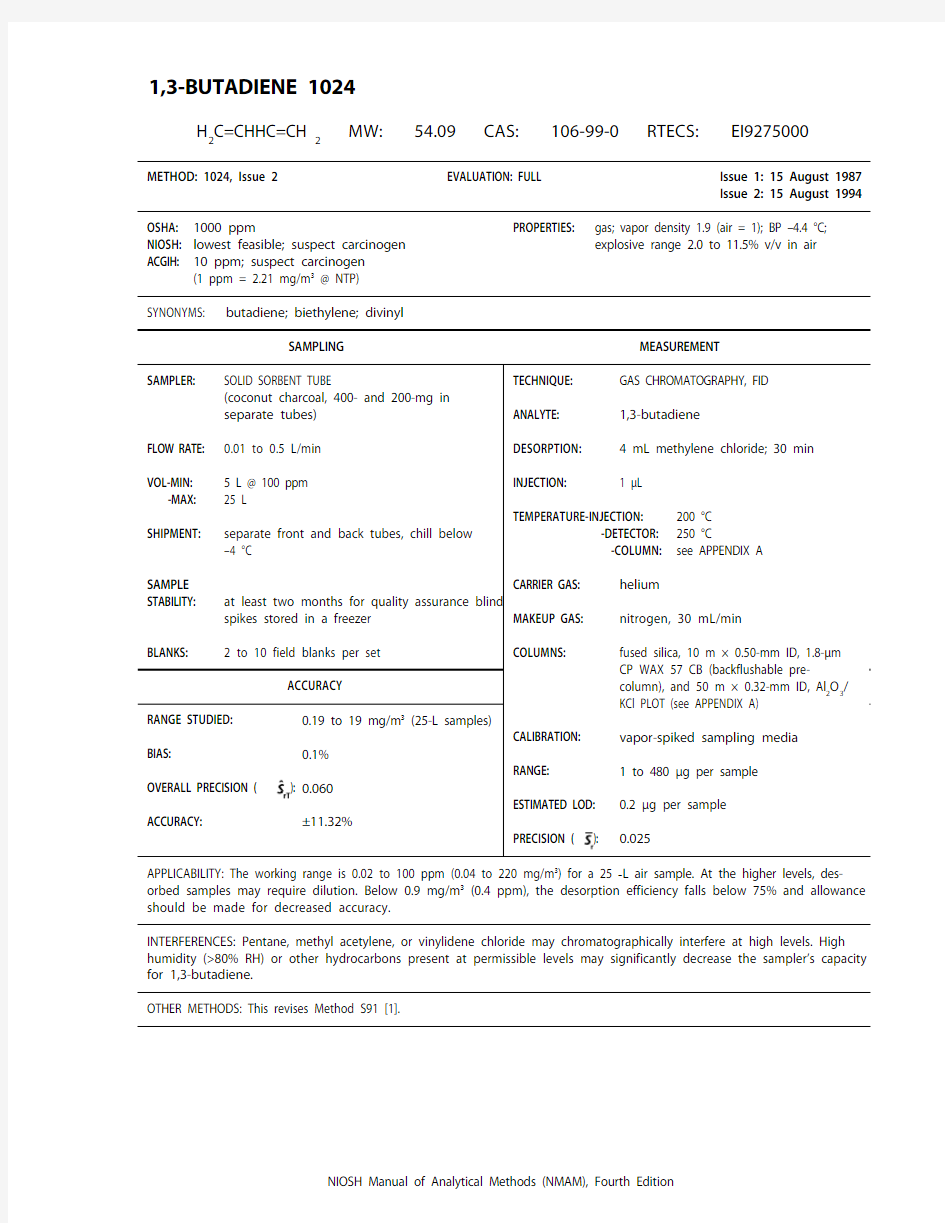

1,3-BUTADIENE 1024
H 2C=CHHC=CH
2
MW: 54.09 CAS: 106-99-0 RTECS: EI9275000
METHOD: 1024, Issue 2EVALUATION: FULL Issue 1: 15 August 1987
Issue 2: 15 August 1994
OSHA: 1000 ppm
NIOSH: lowest feasible; suspect carcinogen ACGIH: 10 ppm; suspect carcinogen
(1 ppm = 2.21 mg/m3 @ NTP)PROPERTIES: gas; vapor density 1.9 (air = 1); BP –4.4 °C;
explosive range 2.0 to 11.5% v/v in air
SYNONYMS: butadiene; biethylene; divinyl
SAMPLING
MEASUREMENT APPLICABILITY: The working range is 0.02 to 100 ppm (0.04 to 220 mg/m3) for a 25-L air sample. At the higher levels, des-
orbed samples may require dilution. Below 0.9 mg/m3 (0.4 ppm), the desorption efficiency falls below 75% and allowance
should be made for decreased accuracy.
INTERFERENCES: Pentane, methyl acetylene, or vinylidene chloride may chromatographically interfere at high levels. High humidity (>80% RH) or other hydrocarbons present at permissible levels may significantly decrease the sampler’s capacity for 1,3-butadiene.
OTHER METHODS: This revises Method S91 [1].
1,3-BUTADIENE: METHOD 1024, Issue 2, dated 15 August 1994 - Page 2 of 8
REAGENTS:
1. Methylene chloride,* chromatographic quality
with hydrocarbon (cyclohexene) preservative.
2. 1,3-Butadiene,* 99.5%, in cylinder equipped
for gas withdrawal, with needle valve.
3. Helium, purified.
4. Hydrogen, purified.
5. Air, purified.
6. Nitrogen, purified.
7. Water, distilled.
*See SPECIAL PRECAUTIONS.EQUIPMENT:
1. Sampler: Tandem charcoal tubes. Each tube
is flame-sealed glass (8.5 cm long, 8-mm OD,
6-mm ID), has plastic caps for resealing, and
contains activated coconut shell charcoal (such as SKC Lot 120) preceded by silylated glass
wool and followed by a 3-mm urethane foam
plug. The front tube holds 400 mg charcoal.
The back tube holds 200 mg.
2. Personal sampling pump, 0.01 to 0.5 L/min,
with flexible connecting tubing.
3. Refrigerant, bagged (e.g., Blue Ice or dry ice),
and insulated shipping container.
4. Gas chromatograph, flame ionization detector,
integrator, and column (see APPENDIX A).
5. Ice, wet.
6. Vials, 5-mL, 2-mL, 1-mL, and other convenient
sizes, with PTFE-lined septum caps.
7. Pipettes, TD, 4-, 2-, and 1-mL.
8. Syringes, gas-tight, 250-, 100-, 25-, and 10-μL.
9. Beaker, 150-mL.
10. Gas drying tube with serum cap to fit stem and
2-cm piece of plastic tubing to fit over serum
cap.
SPECIAL PRECAUTIONS: 1,3-Butadiene is a potential carcinogen, teratogen, and reproductive hazard [2]. Methylene chloride is toxic, very volatile, and a suspect carcinogen [3]. Work should be performed in a well-ventilated fume hood.
SAMPLING:
1. Calibrate each personal sampling pump with a representative sampler in line.
2. Immediately before sampling, break ends of sampler tubes. Connect smaller tube to personal
sampling pump with flexible tubing and to larger tube with a short piece of plastic tubing.
3. Sample at an accurately known flow rate of 0.01 to 0.5 L/min for a sample size of 5 to 25 L.
4. Separate the tubes, cap, and pack securely for shipment. Chill below –4 °C during shipment and
storage.
SAMPLE PREPARATION:
5. Add 4.0 mL methylene chloride to 5-mL vials and 2.0 mL to 2-mL vials. Loosely cap vials and
thoroughly chill in ice.
6. Place front sorbent sections in 5-mL vials and back sections in 2-mL vials. Discard glass wool and
foam plugs. Immediately cap each vial.
7. Remove from ice and allow to stand 30 min with occasional agitation.
8. Transfer sample solution to appropriate vial and cap if using an autosampler. Thoroughly chill
solution and vial before making transfer.
1,3-BUTADIENE: METHOD 1024, Issue 2, dated 15 August 1994 - Page 3 of 8 CALIBRATION AND QUALITY CONTROL:
NOTE: The accurate measurement of pure 1,3-butadiene gas by gas-tight syringe is a critical step in the calibration. Even a slight obstruction (e.g., flakes of PTFE from the plunger tip which
obstruct the needle) can cause 1,3-butadiene to be liquified as the plunger is depressed,
making delivery incomplete. Bracketing gas samples with water, as described below, allows
the volume taken to be approximately verified, and assures complete delivery. The precision
of the analysis of multiple independent standards is another indicator of the accuracy of the
volumes taken.
9. Make up stock solutions in triplicate at three concentration levels, e.g., 200 μL of 1,3-butadiene gas
in 1 mL solution, and both 200 and 50 μL of gas in 4 mL solution:
a. Prepare a beaker and drying tube assembly as shown. Bubble 1,3-butadiene under the lower
edge of the drying tube so that water is displaced and the gas is trapped in the tube.
Plastic tubing
Water
Serum cap
Gas drying tube filled with water
Beaker
Water
b. Pipet 1 or 4 mL of methylene chloride into a 1- or 5-mL vial, cap, and thoroughly chill.
c. Take a known amount (50 or 200 μL) of 1,3-butadiene from the drying tube with a 100- or 250-μL
gas-tight syringe. Bracket the gas in the syringe with small amounts of water (5 to 10% of syringe volume) taken from the area above the serum cap before and after withdrawing the gas. Do not take water from inside the drying tube, since it may contain a significant amount of dissolved
1,3-butadiene.
d. Slowly inject the 1,3-butadiene and water below the surface of the methylene chlorid
e.
e. Agitate and continue to chill the vial to complete dissolution.
10. Calibrate daily with media blanks and triplicate independent media standards of at least six levels
ranging from, e.g., 0.5 to 200 μL 1,3-butadiene gas per sample:
a. Break ends of larger sampler and attach to personal sampling pump with flexible tubing.
b. Take pure gas (50 or 200 μL, as in step 9.c) for the higher levels, or 40 μL of stock solution for
lower levels.
c. Inject the gas and surrounding water plugs or the stock solution at a point inside the sampler
near the glass wool plug while drawing clean air through tube at 0.05 L/min. Continue to draw air through the tube for 5 min or just until the stock solution evaporates.
d. Seal tube with plastic caps.
1,3-BUTADIENE: METHOD 1024, Issue 2, dated 15 August 1994 - Page 4 of 8
e. Store at temperature below –4 °C overnight, then desorb (steps 5 through 8).
f. Analyze media standards and blanks together with samples (steps 13 and 14).
g. Convert gas volumes to masses, correcting for compressibility and water vapor (see APPENDIX B),
and prepare a calibration graph (peak areas or heights vs. concentration of 1,3-butadiene taken in μg/mL).
11. Determine desorption efficiency (DE) at least once for each lot of charcoal used for sampling in
calibration range (step 10).
a. Dilute the stock solutions (step 9) with methylene chloride to extend the range of standards
down to 0.1 μg/mL. Avoid including water in the portions diluted.
b. Transfer solutions as in step 8 if using an autosampler, and analyze together with media
standards (steps 13 and 14).
c. Convert gas volumes to masses, correcting for compressibility and water vapor (see APPENDIX B),
and prepare DE calibration graph of peak area or height vs. μg/mL 1,3-butadiene.
d. Read the concentrations, μg/mL, in media standards and blanks from DE calibration graph and
multiply by the desorption volume to calculate the masses recovered.
e. Prepare a graph of DE vs. μg taken. DE = (mass found – blank mass)/(mass taken).
12. Analyze three quality control blind spikes to insure that calibration graph (step 10) is in control. MEASUREMENT:
13. Set gas chromatograph according to manufacturer’s recommendations and to conditions given on
page 1024-1. Inject sample aliquot manually using solvent flush technique or with autosampler.
NOTE: If detector response is above range of working standards, dilute with methylene chloride, reanalyze, and apply appropriate dilution factor in calculations.
14. Measure peak area or height.
NOTE: Vinylidene chloride, an impurity in methylene chloride, elutes just after 1,3-butadiene and may be used as an internal standard.
CALCULATIONS:
15. Determine the concentration, μg/mL, of 1,3-butadiene found in each sample front () and back ()
sorbent section from calibration graph (step 10), and multiply by desorption volume, , mL, and dilution factor, if any, to calculate the mass, μg, found.
NOTE 1: This calibration method corrects for media blank and DE. Do not duplicate corrections.
NOTE 2: For any sampler with > /10, report breakthrough and possible sample loss.
EVALUATION OF METHOD:
The capacity of a 400-mg charcoal sorbent section was 31 L for a sample at 80% RH and approximately 56 ppm 1,3-butadiene. When exposed to 0.7 and 2.5 mL of pure 1,3-butadiene gas followed by 80% RH air, breakthrough occurred after 35 L and 28.5 L, respectively. The corresponding respective time-weighted average concentrations were 20 and 88 ppm.
water to media standards just after spiking or during desorption had no significant effect on desorption efficiencies.
1,3-BUTADIENE: METHOD 1024, Issue 2, dated 15 August 1994 - Page 5 of 8
In a study of temperature effects on storage stability, 400-mg charcoal tubes were spiked with 26 μg 1,3-butadiene and stored either at ambient temperature or in a freezer below –4 °C. Recoveries were measured relative to media standards stored overnight in the freezer. The recoveries (and days stored) were 94% (7), 93% (14), and 98% (21) for the frozen samples, and 95% (1), 76% (7), 61% (14), and 65% (21) for the ambient samples.
In a preliminary evaluation of precision and accuracy, charcoal tubes were spiked with 125 μg 1,3-butadiene via calibrated sampling valve. The recovery was 102.2% versus media standards (corrected
concentration was independently determined by packed column gas chromatography with thermal conductivity detection. Media standards were prepared via calibrated sampling valves. The recovery
parts of the sampling valve. The study was repeated at 4.71 μg, with the three lowest levels of media
of the response pooled for all levels was 0.033. Assuming a sampling pump error of 0.05, the precision () of the total sampling and analytical
to experimental errors in the preparation and analysis of standards and samples rather than a true bias in the method. At lower levels, based on the linear response and near-zero intercept observed for the standard solution calibrations and the higher than expected desorption efficiencies for the samples, there appeared to be a positive bias in the preparation of the simulated samples.
The method has been used in six industrial hygiene surveys, for a total of 621 samples, most of which were collected under conditions of high ambient temperature and humidity. Only two samples showed significant breakthrough ( > /10). Results for field samples at levels as high as 7.3 mg per sample were not significantly changed by dilution and reanalysis. In all, over 2000 analyses were made over a period of six months without any deterioration of the chromatographic columns. During the course
of the analyses, twenty sets of standard solutions and media standards were prepared and analyzed, each set consisting of triplicates at each of five levels corresponding to 1.08 to 1.10, 4.32 to 4.40, 17.3 to 17.6, 108 to 110, and 432 to 441 μg per sample. For the five levels of standard solutions, the respective pooled relative standard deviations of the observed responses were 0.093, 0.074, 0.059, 0.055, and
0.071. For each set of standard solutions, the deviations of the responses were determined relative to the line resulting from a weighted linear regression of response on concentration. The 95% confidence intervals for the mean relative deviations from linearity for the five levels were –0.002 ± 0.003, 0.000
solution calibrations were 60.4 ± 0.4, 66.4 ± 0.3, 70.5 ± 0.2, 86.2 ± 0.3, and 91.2 ± 0.2.
The analysis of quality assurance blind spikes provided additional data indicating that samples were stable when stored below –4 °C, and that average recoveries, calibrated against media standards, ranged from 96 to 107%. Seventy-seven blind spikes were prepared at six levels, 19.9 to 21.9, 48.6 to 52.6, 104 to 110, 199 to 219, 398 to 438, and 663 μg per sample, stored in a freezer, and analyzed along with the field samples. The storage times ranged from 3 to 134 days; the average was 59 days. For the six levels of blind spikes, the respective relative standard deviations for recoveries were 0.210, 0.092,
1,3-BUTADIENE: METHOD 1024, Issue 2, dated 15 August 1994 - Page 6 of 8
0.054, 0.091, 0.126, and 0.056; the respective 95% confidence intervals for the mean recoveries were 0.986 ± 0.032, 0.961 ± 0.014, 0.994 ± 0.008, 1.029 ± 0.015, 1.064 ± 0.021, and 1.074 ± 0.021. Prior to linear regression of the recoveries versus the amounts spiked and/or days stored, three results, two high and one low, were determined to be outliers by application of one-sided Grubbs tests [4] at the 2.5% significance level and were dropped from the data set. Linear regression of percent recovery on days stored for the data segregated by level resulted in respective slopes and 95% confidence intervals of 0.060 ± 0.080, 0.005 ± 0.128, –0.003 ± 0.092, 0.060 ± 0.179, 0.249 ± 0.188, and 0.018 ± 0.247 percent per day. Thus, the only statistically significant correlation between recovery and days stored was at the next to highest level, for a gain rather than loss over time. Over all levels, the slopes and 95% confidence intervals for recovery versus amounts spiked and days stored were 0.017 ± 0.009 percent per μg and 0.045 ± 0.051 percent per day, respectively. Thus, according to the latter model: the recovery for the blind spikes increased at a rate corresponding to approximately 11% over the range prepared; as stored, the blind spikes appeared to be stable—the 95% confidence interval of the slope over time indicated a maximum gain of 5.7% or loss of 0.4% during the average 59-day storage period.REFERENCES:
[1] NIOSH Manual of Analytical Methods, 2nd. ed., V. 2, S91, U.S. Department of Health Education, and Welfare, Publ. (NIOSH) 77-157-B (1977).
[2] NIOSH Current Intelligence Bulletin 41, “1,3-Butadiene,” U.S. Department of Health and Human Services, Publ. (NIOSH) 84-105 (1984).
[3] NIOSH Current Intelligence Bulletin 46, “Methylene Chloride,” U.S. Department of Health and Human Services, Publ. (NIOSH) 86-114 (1986).
[4] Grubbs, F. E. “Procedures for Detecting Outlying Observations in Samples,” Technometrics , 11(1), 1–21, (February, 1969).
[5] MacCallum, R. N., and J. J. McKetta. “Low-Pressure Zs of C 4 Hydrocarbons,” Hydrocarbon Process. Petrol. Refiner , 42(5), 191–194 (1963).METHOD WRITTEN BY:
R. Alan Lunsford, Ph.D., Yvonne T. Gagnon, NIOSH/DPSE, and John Palassis, NIOSH/DTMD.APPENDIX A. GAS CHROMATOGRAPH COLUMN SELECTION, INSTALLATION, AND OPERATION:Any column which separates 1,3-butadiene from the other substances present, and which otherwise provides satisfactory chromatographic performance, is acceptable. The column specified in NIOSH Method S91 [1] is 6 m × 3-mm OD stainless steel, packed with 10% FFAP on 80/100 mesh Chromosorb W AW-DMCS. It provides a convenient separation of 1,3-butadiene from the desorbing solvent.
However, if other C 4 to C 6 hydrocarbons are present, interferences are likely. For the development of this method, a 50 m × 0.32-mm ID fused-silica porous-layer open-tubular (PLOT) column coated with Al 2O 3/KCl (Cat. # 7515, Chrompack, Bridgewater, NJ) was chosen as the analytical column because it provides a very efficient separation at temperatures above ambient. However, water from the samples deactivates the aluminum oxide, reducing retention times, and high-boiling or polar substances may accumulate on the column and irreversibly degrade the separation. The degradation was eliminated by using a backflushable pre-column, i.e., 10 m × 0.5-mm ID fused-silica CP Wax 57 CB (Cat. # 7648, Chrompack, Bridgewater, NJ). The pre-column allows light hydrocarbons to pass through, but water, methylene chloride, and polar or high boiling components are retained and can be backflushed. Eliminating the solvent peak significantly reduces the time required to complete the analysis.
Figures 1 and 2 schematically illustrate the installation and operation of the recommended columns in a Hewlett-Packard 5880A gas chromatograph with split-splitless capillary inlet systems installed in the “B” and “C” injector positions. The only change to the “B” system involves the normally closed (NC) port of
1,3-BUTADIENE: METHOD 1024, Issue 2, dated 15 August 1994 - Page 7 of 8
the “B” solenoid valve. Originally, it was connected to the capped port of the tee in the “B” septum purge line. (If desired, switching between normal operation of the “B” system and backflushable pre-column operation could be easily achieved by adding a manually operated three-way valve.) Replumb the components of the “C” system as shown, and extend lines from the normally open (NO) port of the “C” solenoid and the “C” backpressure regulator into the oven. Connect the lines and columns with a zero-dead-volume cross (e.g., Part # ZX1, Valco, Houston, TX) and graphite ferrules.
Set the initial oven temperature to 50 °C and the “C” backpressure regulator to 185 kPa. With the solenoid valves activated (inject mode), set the “C” flow control to 20 mL/min and the “B” controls so that the effluent from the analytical column and the “C” split vent total 10 mL/min. Then, with the solenoid valves deactivated (backflush or normal mode), adjust the “B” backpressure regulator until
the flow from the “C” split vent returns to the value previously measured. This establishes a reverse flow of 10 mL/min through the pre-column. Program the oven to hold the initial temperature (50 °C) for 2 min, then rise to 120 °C at 20 °C/min, and hold for 8 min. Adjust the time from injection to backflush by injecting standards and progressively decreasing the time from 2 min until the methylene chloride peak is removed without attenuating the butadiene peak. It may be necessary to clear higher hydrocarbons from the analytical column by programming the oven to 200 °C at 30 °C/min and holding 4 min. Program the solenoid valves to be activated after each run to prepare for the next injection.
Using the backflushable pre-column, there remains a slight problem with retention drift. While in inject mode, the pre-column strips residual water from the carrier gas. This activates the aluminum oxide surface of the analytical column and causes retention to increase. The effect is most noticeable when starting up after the system has been idle. When beginning a sequence of samples, it is advisable to analyze solvent blanks until the retention drift (e.g., of vinylidene chloride) becomes tolerable. APPENDIX B. CONVERSION OF 1,3-BUTADIENE VOLUME TO MASS
MacCallum and McKetta [5] determined the compressibility factor, , which corrects for non-ideal behavior, for 1,3-butadiene at temperatures, , ranging from 10 to 75 °C, and pressures, , from approximately 420 to 1050 mm Hg. Multiple regression of the observed values against , , and , yields the following equation (standard error of the estimated is 0.000635 for 13 degrees of freedom):
,
where: a = 1.00095, , , .
The mass, , of 1,3-butadiene, corrected for compressibility and the presence of water vapor (when the gas is stored above water), may be calculated by the following equation:
where: = vapor pressure of water @ °C (mm Hg),
= volume of 1,3-butadiene (μL),
54.09 = molecular weight of 1,3-butadiene (g?mol–1),
62.36 = gas constant (mm Hg?L?mol–1?K–1),
273.2 = absolute temperature of 0 °C (K).
1,3-BUTADIENE: METHOD 1024, Issue 2, dated 15 August 1994 - Page 8 of 8
Figure 1.
Flow diagram for pre-column system in inject mode.
“B”Septum purge “B”Split vent
“C”Split vent
Carrier inlet Carrier inlet
Figure 2. Flow diagram for pre-column system in backflush (normal) mode.
“B”Septum purge “B”Split vent
“C”Split vent
Carrier inlet Carrier inlet
再生纸厂废水处理初步设计书
福州大学至诚学院 《水污染操纵工程》课程设计 设计题目:某再生纸厂废水处理站初步设计专业:环境工程 年级: 组长: 小组成员: 指导教师:
2012年 06月 20 日
目录 第1章:任务书 (1) 1.1:设计范围 (1) 1.2:设计要求 (1) 1.3:设计依据、规范和原则 (2) 1.4:废水水质水量 (3) 第2章:概述...................................4第3章:工艺比选..............................4第4章:工艺计算 (5) 4.1粗细格栅设计计算 (6) 4.2调节池设计计算 (9) 4.3气浮池设计计算 (10) 4.4水解酸化池设计计算 (14) 4.5接触氧化池设计计算 (16) 4.6竖流式沉淀池设计计算 (22) 4.7重力浓缩池设计计算 (25) 4.8 污泥脱水设计计算 (26) 4.9溶药池、储药罐设计计算 (27)
第1章任务书 某再生纸厂废水处理站初步设计任务书,由甲方提供的要求和资料如下: 1.1设计范围 对某纸业的造纸废水进行处理,要紧是废纸制浆废水和白水,其中要紧是白水,一部分白水回用于造纸系统的碎浆、和浆、混合等工段,剩余的白水经废水处理设施处理后排入厂界之外的沙溪河。 1.2设计要求 (1)工艺技术方案比选和工艺流程设计:依照所收集的原始资料和文献资料进行某纸业再生纸废水处理工艺技术方案优选,并在此基础上完成工艺流程设计; (2)设计参数选择与计算:依照上述方案比选和工艺流程设计,结合相关工程运行调试类比,或工艺条件试验结果,或工程手册资料,完成各单元操作或构筑物工艺参数优化选择并计算,并依照计算结果编制设计计算书; (3)主体构筑物结构设计:依照各单元操作或构筑物工艺参数选择结果和环境工程制图格式规范要求,完成主体构筑物结构设计和图纸清
丁二烯工艺设计讲解
目录 1 引言 (37) 2 工艺路线 (37) 2.1 生产的基本原理 (37) 2. 2 工艺路线的对比与选择 (37) 2. 3 DMF法碳四抽提丁二烯装置的特点 (38) 2. 4 物料衡算 (39) 2. 5 装置工艺流程图 (40) 2. 6 工艺流程说明 (40) 2.6.1 第一萃取精馏部分 (40) 2.6.2 第二萃取精馏部分 (42) 2.6.3 丁二烯净化部分 (43) 2.6.4 溶剂净化部分 (44) 2. 7 工艺控制 (44) 2.7.1 原料质量变化对产品的影响及调节方法 (45) 2.7.2 主要工艺条件的变化对产品质量的影响 (46) 结论 (49) 参考文献 (50) 致谢 (51)
1 引言 丁二烯来源:从油田气、炼厂气和烃类裂解制乙烯的副产品中都可获得碳四馏分。碳四系列的基本有机化工产品主要有丁二烯、顺丁烯二酸酐、聚丁烯、二异丁烯、仲丁醇、甲乙酮等,它们是有机化学工业的重要原料。无论是裂解气深冷分离得到的碳四馏分,还是经丁烯氧化脱氢得到的粗丁二烯,均是以碳四各组分为主的烃类混合物,主要含有丁烷、正丁烯、异丁烯、丁二烯,它们都是重要的有机化工原料[1,2]。 C4的分离与C2、C3馏分相比,其最大的特点是各组分之间的相对挥发度很小,使分离变得更加困难,采用普通精馏方法在通常条件下将其分离是不可能的。为此工业生产中常用在碳四馏分中加入一种溶剂进行萃取的特殊精馏来实现对C4馏分的分离[3-5]。 2 工艺路线 2.1 生产的基本原理 由于碳四原料中大部分组分与丁二烯-1,3之间的沸点较为接近,而且相互之间有共沸物产生,这样采用一般的精馏方法很难进行分离开,所以为了得到目标产品(丁二烯)就必须采用特殊分离方法——萃取精馏。萃取精馏的原理就是:向被分离物料碳四原料中加入一种新的组分——萃取溶剂二甲基甲酰胺(DMF),它的加入使得原来物料中各组分之间的相对挥发度发生明显变化,从而使物料中难以用普通精馏方法分离的组分如:顺丁烯-2和反丁烯-2等组分在第一萃取精馏塔分离出来,乙基乙炔和乙烯基乙炔等组分在第二萃取精馏塔分离出来。 经过两段萃取精馏得到的粗丁二烯再经过两段普通精馏即得到产品丁二烯。普通精馏的原理是利用混合物中各组分在相同压力下相对挥发度不同的特点,使混合物处于气—液两相共存时各组分在液相和气相中的分配量不同从而将各组分分离开。 甲基乙炔和水等轻组分在第一精馏塔顶脱除,第二精馏塔则用于脱除在萃取精馏部分未能完全脱除的顺丁烯-2、丁二烯-1,2、乙基乙炔、碳五等重组分,塔顶得到产品丁二烯。 2. 2 工艺路线的对比与选择 目前世界上大规模工业化生产丁二烯-1,3的方法主要有三种:乙腈法(ACN)、二甲基甲酰胺法(DMF)和N-甲基砒硌烷酮法(BASF)。
研究课题:C4抽提丁二烯工艺流程的研究
班级:广汇化工102班 姓名:陈录顺 学号:11 研究课题:C 4抽提丁二烯工艺流程的研究
目录索引 【摘要】 (3) 1、乙腈法(ACN法) (3) 图1乙腈法分离丁二烯工艺流程图 (3) 丁二烯萃取精馏塔(乙腈法)生产中的异常现象举例 (5) 2 、二甲基甲酰胺法(DMF 法) (6) 图2 二甲基甲酰胺抽提丁二烯流程图 (6) 3、N-甲基吡咯烷酮法(NMP法) (6) 图3 NMP法丁二烯抽提装置工艺流程 (7) 相关知识链接: (8) 参考文献 (8)
【摘要】:液体丁二烯极易挥发,闪点低,易燃易爆,其爆炸极限为2~11.5体积。物理性质丁二烯微溶于水和醇,易溶于苯、甲苯、乙醚、氯仿、四氯化碳、汽油、无水乙腈、二甲基甲酰丁二烯分子结构中具有共轭双键,化学性质胺、N—甲基吡咯烷酮、糠醛、二甲基亚砜等有机活泼,能与氢、卤素、卤化氢等起加成反溶液。应。丁二烯有毒,低浓度下能刺激粘膜和呼吸道,高丁二烯容易发生自身聚合作用,也容易与化学性质浓度能引起麻醉作用。其它单体进行共聚作用,它是生产合成橡胶如丁二烯和苯乙烯共聚可生产丁苯橡胶;丁二烯在和各种树脂的重要原料。催化剂作用下可发生定向聚合反应生成顺丁橡胶;丁二烯与丙烯腈共聚生成丁腈橡胶;若丁二烯、苯乙烯和丙烯腈三元共聚可生成ABS树脂。另外,世界上某些国家发展的丁二烯氯化得到氯丁用途二烯之后进行聚合生产氯丁橡 胶;以及用丁二烯合成己二腈和己二酸,进一步合成尼龙—6和尼龙—66等化学纤维。 关键字:丁二烯乙腈法二甲基甲酰胺法 N-甲基吡咯烷酮法 1、乙腈法(ACN法) 乙腈法是以含水5%~10%的乙腈为溶剂,以萃取精馏的方法分离丁二烯。我国于1971年5月由兰化公司合成橡胶厂自行开发的乙腈法C 4 抽提丁二烯装置试车成功。该装置采用两级萃取精馏的方法,一级是将丁烷、丁烯与丁二烯进行分离,二级是将丁二烯与炔烃进行分离。其工艺流程见图1。 由裂解气分离工序送来的C 4馏分首先送进碳三塔(1)碳五塔(2),分别脱除C 3 馏分和 C 5馏分,得到精制的C 4 馏分。 精制后的C 4 馏分,经预热汽化后进入丁二烯萃取精馏塔(3)。丁二烯萃取精馏塔分 为两段,共l20块塔板,塔顶压力为0.45Mpa,塔顶温度为46℃,塔釜温度114℃.C 4馏分由塔中部进入,乙腈由塔顶加入,经萃取精馏分离后,塔顶蒸出的丁烷、丁烯馏分进入丁烷、丁烯水洗塔(7)水洗,塔釜排出的含丁二烯及少量炔烃的乙腈溶液,进入丁二烯蒸出塔(4)。在塔(4)中塔釜排出的乙腈经冷却后供丁二烯萃取精馏塔循环使用,丁二烯、炔烃从乙腈中蒸出去塔顶,并送进炔烃萃取精馏塔(5)。经萃取精馏后,塔顶丁二烯送丁二烯水洗塔(8),塔釜排出的乙腈与炔烃一起送入炔烃蒸出塔(6)。为防止乙烯基乙炔爆炸,炔烃蒸出塔(6)顶的炔烃馏分必须间断地或连续地用丁烷、丁烯馏分进行稀释,使乙烯基乙炔的含量低于30%(摩尔),炔烃蒸出塔釜排出的乙腈返回炔烃蒸出塔循环使用,塔顶排放的炔烃送出用作燃料。 在塔(8)中经水洗脱除丁二烯中微量的乙腈后,塔顶的丁二烯送脱轻组分塔(10)。在塔(10)中塔顶脱除丙炔和少量水分,为保证丙炔含量不超标,塔顶产品丙炔允许伴随60%左右的丁二烯,塔釜丁二烯中的丙炔小于5ppm,水分小于10ppm。对脱轻组分塔来说,当釜压为0.45 MPa、温度为50℃左右时,回流量为进料量的1.5倍,塔板为60 块左右,即可保证塔釜产品质量。 图1乙腈法分离丁二烯工艺流程图
详细的制粒技术及经验
药智网免费提供药品标准查询”https://www.360docs.net/doc/7b3033579.html,/biaozhun.htm 一、制粒技术概念 制粒(granulation)技术:是把粉末、熔融液、水溶液等状态的物料加工制成一定形状与大小的粒状物的技术。 制粒的目的:①改善流动性,便于分装、压片;②防止各成分因粒度密度差异出现离析现象;③防止粉尘飞扬及器壁上的粘附;④调整堆密度,改善溶解性能;⑤改善片剂生产中压力传递的均匀性;⑥便于服用,方便携带,提高商品价值。 制粒方法:湿法制粒、干法制粒、一步制粒、喷雾制粒,其中湿法制粒应用最多。 制粒技术的应用:在固体制剂,特别在颗粒剂、片剂中应用最为广泛。 二、制粒方法 (一)、湿法制粒 湿法制粒:在药物粉末中加入粘合剂或润湿剂先制成软材,过筛而制成湿颗粒,湿颗粒干燥后再经过整粒而得。湿法制成的颗粒具用表面改性较好、外形美观、耐磨性较强、压缩成形性好等优点,在医药工业中应用最为广泛。 湿法制粒机理:首先是粘合剂中的液体将药物粉末表面润湿,使粉粒间产生粘着力,然后在液体架桥与外加机械力的作用下制成一定形状和大小的颗粒,经干燥后最终以固体桥的形式固结。 湿法制粒主要包括制软材、制湿颗粒、湿颗粒干燥及整粒等过程。 1、制软材:将按处方称量好的原辅料细粉混匀,加入适量的润湿剂或粘合剂混匀即成软材。 制软材应注意的问题 (1)粘合剂的种类与用量要根据物料的性质而定; (2)加入粘合剂的浓度与搅拌时间,要根椐不同品种灵活掌握; (3)软材质量。由于原辅料的差异,很难定出统一标准,一般凭经验掌握,用手捏紧能成团块,手指轻压又能散裂得开。 (4)湿搅时间的长短对颗粒的软材有很大关系,湿混合时间越长,则粘性越大,制成的颗粒就越硬。 2、制湿颗粒:使软材通过筛网而成颗粒。颗粒由筛孔落下如成长条状时,表明软材过湿,湿合剂或润湿剂过多。相反若软材通过筛孔后呈粉状,表明软材过干,应适当调整。 常用设备:摇摆式颗粒机、高速搅拌制粒机 筛网:有尼龙丝、镀锌铁丝、不锈钢、板块四种筛网。 3、湿颗粒干燥:过筛制得的湿颗粒应立即干燥,以免结块或受压变形(可采用不锈钢盘将制好的湿颗粒摊开放置并不时翻动以解决湿颗粒存放结块及变形问题)。 干燥温度:由原料必性质而定,一般为50-60℃;一些对湿、热稳定的药物,干燥温度
再生纸造纸废水处理方案
再生纸造纸废水处 理方案 1
再生纸造纸废水处理改造工程 技 术 方 案 目录 第一章项目概况 (1) 第二章设计依据、原则及范围 .................. 2 2.1.设计依据 1
2. 2 .设计原则 (3) 2. ............................................................................................... 3.设计范围. (3) 第三章工艺设计 (3) 3. ................................................................................................... 1.设计规模. (3) 3. 2.设计进水水质和排放要求 (3) 第四章处理工艺的选择和设计 (4) 4.1.废水来源及选择 (4) 4.2.设计中针正确主要问题 (5) 4.3.主要工艺简介 (7) 4.4. ................................................................................................ 工艺流程 (9) 4.5 .设计处理效果预测 (11) 4.2 .废水处理单元设计 (11) 第五章工程概算、工程经济指标及项目建设工期 (14) 5. 1.工程概算 (14) 5. 2.综合经济指标一览表 (16) 5. 3.项目建设周期 (17) 第一章项目概况
再生纸造纸能有效地利用资源、保护生态环境, 因而越来越受 2 2020 年6 月23 日
碳四抽提丁二烯
毕业设计(论文)设计(论文)题目: 学院名称:化学工程学院 专业:化学工程与工艺 班级: 姓名:学号 指导教师:职称
摘要 丁二烯是一种具有广泛用途的化工产品,其生产、制备的研究进行了数十年。目前仍然未停止对其工艺的调整与改进。工业生产中常用在碳四馏分中加入一种溶剂进行萃取的特殊精馏来实现对C4馏分的分离。本设计以从碳四中抽提丁二烯为目的,依据经济、节约、环保、科学的理念,制定出抽提段的工艺。目前世界上大规模工业化生产丁二烯-1 的方法主要有三种:乙腈法(ACN)、二甲基甲酰胺法 ,3 (DMF)和N-甲基砒硌烷酮法(BASF)。工艺采用DMF法,从碳四混合物中抽提出符合工艺要求的丁二烯。设计中对DMF法抽提丁二烯的原理、工艺、操作规范、物料衡算、废物处理等发面进行了阐述。DMF抽提丁二烯装置可分为两个部分:萃取部分和精馏部分。萃取部分包括第一萃取精馏系统和第二萃取精馏系统,碳四原料中的丁烷、丁烯等在第一萃取精馏系统中脱除,乙烯基乙炔、一部分乙基乙炔等组分在第二萃取精馏系统中脱除;精馏部分包括丁二烯净化和溶剂精制两系统,除去其中的二甲胺、甲基乙炔、水、顺丁烯-2等杂质,得到丁二烯成品;而溶剂精制系统是将循环溶剂中的水分,二聚物等轻组分及焦油等重组分除去,保持循环溶剂的质量。设计结果科学、合理,实用、经济,比较好的完成了当初所设定的目标任务。 关键词:碳四;丁二烯;抽提;DMF
ABSTRACT Butadiene is a widely used chemical products, its production, research on the preparation for decades. At present, still did not stop the process of adjustment and improvement. Special rectification commonly used in industrial production in four fractions of carbon with a solvent extraction to achieve separation of C4 fractions. The design for the purpose of butadiene extraction from carbon 4, on the basis of the economic, environmental protection, conservation, scientific ideas, develop process extraction section. The large-scale industrial production of butadiene with -1, there are three main methods: acetonitrile (ACN), two methyl formamide (DMF) and N- methyl pyrrole azululanone method (BASF). Process using DMF method, is proposed to meet the process requirements of the butadiene extraction from carbon four mixture. The design of DMF butadiene extraction principle, process, operation, material balance, waste disposal and other aspects are discussed. DMF Extraction Butadiene device can be divided into two parts: the extraction and distillation. The extraction part includes the first extractive distillation system and the second system of extractive distillation, carbon four of raw materials, such as butane butene in the first extraction distillation system removal, vinyl acetylene, a part of ethyl acetylene and other components removal in second extraction distillation system; distillation part includes the butadiene purification and solvent refining two system, remove the two -, methyl acetylene, water, CIS butene -2 impurities, butadiene get finished products; and solvent refining system is the circulation of water in the solvent, two dimers and other light components and tar and other restructuring removed, maintain the quality of circulating soluble agent. The design result is scientific and reasonable, practical, economic, better to complete the target mission set. Key Words:Butadiene;C4 Fractions;Extraction;DMF
中药制粒工艺精要
中药制粒工艺精要 一、制颗粒目的 1、增加细粉流动性:细粉流动性差,影响定量流入片剂模孔或胶囊,从而影响片重差异或胶囊装量 2、减少细粉中空气:细粉表面大,可吸大量空气,压片不能及时逸出,易产生裂片、松片等现象 3、降低细粉粘附性:细粉表面大,易粘附在冲头上,造成粘冲 4、避免细粉分层:片剂或胶囊剂中各种药物比重不同,压片时受到震动T混合细粉分层T各药含量比例失调,除少数晶性药物,可直接压片药物,均需制粒改变药物物理性状符合压片要求 二、制颗粒过程分为原辅料处理、制粒、干燥和总混工序。 1、原料处理 ①提取:中药材一般多用水提或醇提,提取后回收乙醇,浓缩至一定浓度时移放冷处静置一定时间,使 沉淀完全,过滤,滤液低温浓缩至稠膏,比重 1.30~1.35 (50~60C)。 ②粉碎:含有较低量芳香挥发性成分的药材,如广木香、化橘红;热敏性药材,如六神曲、杏仁霜;贵重药材如人参、麝香;含淀粉多的药材如山药等可以细粉兑入,并可减少辅料用量。 2、辅料处理 ①糖粉:为蔗糖细粉,一般在粉碎前先低温(60C)干燥,粉碎(80~100 目)。糖粉易吸潮结块,应密 封保存;若保存时间较长,临用前最好重新干燥过筛,以提高吸水性和颗粒质量。可用乳糖粉代替糖粉。 ②糊精:一般用可溶性糊精,作用是使颗粒易于成型;在使用前应低温干燥、过筛。 ③B-CD :与挥发油制成包合物,再混匀于其他药物制成的颗粒中,可使液体药物粉末化,且增加油性药物的溶解度和颗粒的稳定性。 ④其他辅料:可溶性淀粉、甘露醇、微晶纤维素、微粉硅胶、羟丙基淀粉等,因来源,价格等原因,目前使用不多,但因具有不吸湿、性质稳定等优点,应用前景广阔。 3 、制粒方法 稠浸膏制粒:将干燥的糖粉、糊精置适当容器中,,再加入稠浸膏搅拌混匀,必要时加适量50~90%乙醇,调整干湿度及粘性制成“手捏成团,轻压则散”的软材,然后将软材加入摇摆式制粒机料斗中,借钝六角形棱状转轴作往复转动,软材挤压通过筛网(10~14目)制成湿颗粒。湿粒标准是置于掌中簸动,应有沉重感,细粉少,湿粒大小整齐无长条为宜。糖粉、糊精与稠浸膏( 1.35~1.40, 50~60C)比例一般为3:1:1,根据 稠浸膏的比重、性质及用药目的可适当调整,有的颗粒糖粉可至2~5 倍,有的颗粒糊精可至1~1.5 倍,有的 颗粒单用糖粉而不用糊精,辅料总用量不应超过稠膏量的5倍。。此法制得的颗粒极易吸潮,应控制干颗粒含 水量w 6.0% 干浸膏制粒:将稠浸膏真空干燥(或其他方法)制成干浸膏,或稠浸膏加适量干燥的糖粉、糊精制成块 状物,于60~70C干燥得干浸膏,再粉碎成细粉,加适量糖粉、糊精,混匀,加乙醇制软材、制粒、干燥、整 粒即得,此法制粒费工时,但颗粒质量较好,色泽均匀;或将干浸膏直接粉碎成40~50 目颗粒,此法制得的颗粒呈粉末状,吸湿性较强,包装要严密。 稠浸膏与药材细粉混合制粒:药材细粉(100 目)与适量干燥的糖粉混匀,再加入稠浸膏搅拌混匀,制软材、制粒、干燥、整粒即得,此法可节省辅料,降低成本。 ③制粒设备手工制粒筛:适用于少量制备颗粒。湿颗粒由筛孔落下时应无长条状、块状物及细粉,而成均匀的颗 粒 为佳。若软材粘附在筛网中很多,或挤出不成粒状而是条状物,表示软材过软,应加入适当辅料或药物细粉调整湿度;若软材成团块不易压过筛网表示软材过粘,可适当加入高浓度乙醇调整并迅速过筛;若通过筛网后呈疏松的粉粒或细粉多,表示软材太干,粘性不足,可适当加入粘合剂(如低浓度淀粉浆等)增加粘度。 摇摆式颗粒机:适用于大量生产颗粒。软材加入加料斗中的量与筛网松紧影响湿颗粒的松紧和粗细。如调节软材加入加料斗中的量与筛网松紧不能适宜湿颗粒时,应调节稠浸膏与辅料用量,或增加过筛次数来解决。 喷雾干燥制粒 4、干燥 湿颗粒应及时干燥以免结块或受压变型,干燥温度60~80 C,加热温度应逐渐升高,否则颗粒表面形成
中国矿业大学 某造纸厂废水处理工程设计
《水处理工程技术课程设计报告》 题目 时间 班级 姓名 序号 指导教师 教研室主任 系教学主任 2011年 06 月 11 日
目录 第1章概述 (4) 1.1进水资料及排放标准 (4) 1.2设计出水水质 (4) 1.3设计依据 (4) 1.4设计原则 (5) 1.5 污水处理工程建设的意义 (5) 1.6当地气象及水文资料 (6) 1.7 厂区地形及设计标高 (6) 第2章处理工艺 (7) 2.1处理工艺选择 (7) 第3章处理工艺说明 (10) 3.1格栅与格栅井 (10) 3.2中和池 (10) 3.3初沉池 (11) 3.4 SBR反应器 (11) 3.5 污泥浓缩池 (13) 3.6 带式压滤机 (13) 3.7 加药装置 (13) 3.8综合楼 (14) 第4章处理构筑物的设计计算 (14) 4.2 中和池设计计算 (16)
4.3初沉池设计计算 (17) 4.4 SBR池设计计算 (19) 第5章污水厂平面和高程布置 (22) 5.1平面布置 (22) 5.2高程布置 (23) 5.3高程计算 (24)
第1章概述 1.1进水资料及排放标准 该厂年产2万t 包装纸。每天废水平均流量为2200m 3。废水处理后部分排入附近水体,部分回用,因此设计出水水质应达到GB 3544-2011《造纸工业水污染物排放标准》,具体见表1. 表1设计水质、水量和排放要求 1.2设计出水水质 诸多的工程根据同类工程的经验,同时凭借我司在造纸厂污水治理工程中实例,混凝沉淀处理后的废水清澈透明,无异味,接近综合排放标准二级标准水质,完全可以用于再生纸造纸中的碎浆阶段。排放部分废水达到《污水综合排放标准》GB8978-1996 一级标准,即: 污染物指标 数值 污染物指标 数值 COD COD ≤100 mg/L BOD BOD ≤60 mg/L PH 值 7~9 SS 100mg/L 1.3设计依据 1.3.1.《中华人民共和国环境保护法》 1.3. 2.《中华人民共和国水污染防治法》 项目 水量/(m 3.d -1) PH 值 ρ (COD 5)/(mg.l -1 ) ρ(BOD 5)/(mg.l -1) ρ(SS) /(mg.l -1) 废水水质 5000 6~9 1500~2200 600~800 1500~1800
乙腈法生产丁二烯后处理工艺的优化
乙腈法生产丁二烯后处理工艺的优化 摘要:随着科技的不断发展,乙腈法生产丁二烯的技术水平也在不断的提高。本文从丁二烯的用途、乙腈法生产丁二烯后处理工艺优化的必要性、ACN法生产丁二烯的后处理部分及工艺优化等几个方面进行了分析。 关键词:乙腈法;丁二烯;优化 一、前言 近年来,由于人们对丁二烯的需求量不断加大,乙腈法生产丁二烯后处理工艺的优化问题得到了人们的广泛关注。虽然我国在此方面取得了一定的成绩,但依然存在一些问题和不足需要改进,在科学技术突飞猛进的新时期,加强乙腈法生产丁二烯后处理工艺优化的研究,对我国生产丁二烯的技术水平起着重要的意义。 二、丁二烯的用途 丁二烯是一种重要的石油化工基础有机原料和合成橡胶单体,是C4馏分中最重要的组分之一,在石油化工烯烃原料中的地位仅次于乙烯和丙烯。由于其分子中含有共轭二烯,可以发生取代、加成、环化和聚合等反应,使得其在合成橡胶和有机合成等方面具有广泛的用途,可以合成顺丁橡胶(BR)、丁苯橡胶(SBR)、丁腈橡胶、苯乙烯-丁二烯-苯乙烯弹性体(SBS)、丙烯腈-丁二烯-苯乙烯(ABS)树脂等多种橡胶产品,此外还可用于生产己二腈、己二胺、尼龙66、1,4-丁二醇等有机化工产品以及用作粘接剂、汽油添加剂等,用途十分广泛。 三、乙腈法生产丁二烯后处理工艺优化的必要性 粗丁二烯一般还含有其他的C4组分杂质,通常是采用萃取精馏的方法将丁二烯分离开来。乙腈(ACN)及其含水物是常用的萃取剂之一。ACN是丙烯腈生产中的副产物,在我国来源丰富。ACN对C4气体的分离能力较强,工艺要求较低,故以ACN为萃取剂从C4中分离出丁二烯的工艺流程特别适合我国国情,在我国这类装置应用较多。随着近期国内乙烯装置的不断改扩建,就必须了解原有ACN法工业装置的生产状况,以及在此基础上针对国内ACN法生产丁二烯后处理工艺中存在的一些问题进行改进和优化。 四、ACN法生产丁二烯的后处理部分 ACN法生产丁二烯的后处理可以分为3个部分:丁二烯水洗部分、丁二烯精制部分和溶剂回收部分。 1、丁二烯水洗部分 由于ACN的沸点较低,第二萃取精馏塔顶产物(主要是丁二烯)不可避免地
丁二烯装置腈烃比的优化研究
丁二烯装置腈烃比的优化研究 文章研究了丁二烯装置在不同生产负荷下的腈烃比,通过相关试验数据,分析出了在当前的生产条件下,最佳的腈烃比与生产负荷之间的对应关系,这些试验研究有利于丁二烯装置的正常运转,为之后丁二烯装置的稳定运行提供了借鉴依据。 标签:丁二烯装置;腈烃比;优化研究 1 丁二烯装置简介 丁二烯装置采用乙腈法丁二烯萃取精馏工艺,从乙烯装置提供的粗C4原料中分离出纯度为99.5%wt的1,3-丁二烯产品,其中产品回收率非常高,可以达到98%。在生产过程中,主要的副产品有混合丁烷-丁烯、丙炔和C4炔烃、丁二烯和C5等。丁二烯装置的设计能力非常高,目标达到年产十万吨以上,每年的操作时间可以保证近万小时。在利用此装置进行丁二烯生产时,一般是利用萃取精馏的方法,这种方法可以生产出高纯度的1,3-丁二烯,它的原理是在原料中加入一种特殊的溶剂,即乙腈,这种方法可以提高待分离组分的相对挥发度,然后利用精馏的方法分离开原本难以分离的组分。 丁二烯装置在设备的结构和布置上进行了良好的工程设计以及工程实践,整个装置由原料准备单元、萃取精馏单元、压缩单元、丁二烯精馏单元等单元组成,另外,为了保证装置的正常运行,设计人员还在装置中配备了辅助系统。整个装置中最关键的是萃取精馏单元,萃取精馏的目的是,当乙腈溶剂存在时,利用精馏工艺将C4烷烃和C4烯烃从1,3-丁二烯中分离。从原料准备单元送来的C4原料首先经过进料蒸发器进行部分气化,然后进入萃取精馏设备。利用这种方法可以更加方便的实现物质的分离,使得工艺过程生产效率更高。 2 腈烃比的相关研究 在丁二烯装置中,乙腈泵的作用是提供溶剂向丁二烯萃取塔和炔烃萃取塔中提供溶剂乙腈。溶剂的多少直接关系到整个工艺过程的成功与否,因此乙腈泵的工作状态直接关系到整个装置的运转,在研究腈烃比时,必须对乙腈泵进行研究。乙腈泵采用耐高温单端面波纹管进行机械密封。但是这种方式非常容易遭到破坏,一旦发生泄漏,会严重污染环境,而且还会造成安全隐患。因此,这种装置需要一定的改变,这样才能更好的提供溶剂,对乙腈泵进行技术改造之后,因为循环冷却系统的存在,里面的乙腈浓度不存在,不会发生泄漏情况,运行状态良好,消除了安全隐患,同时大大减少了维修费用。这样乙腈泵就能更好的提供溶剂,为研究腈烃比提供方便。 根据装置的相关研究和相关实践,我们得到,腈烃比如果太高,塔内恒定浓度会比较高,这时会增加动力消耗以及蒸汽消耗,并且会使得塔釜反丁浓度太高,从而使最终的产物丁二烯不合格。相反,如果腈烃比比较低的化,C4各组分的
药品制粒干燥方法及设备
一、常压干燥 1、滚筒式干燥器 原理:接触干燥,将已蒸发到一定稠度的药液涂于滚筒加热面使成薄层进行干燥 特点:蒸发面与受热面大,大大缩短干燥时间,可连续生产 缺点:占据空间大 2、厢式干燥器 原理:空气干燥 特点:结构简单,投资少,操作方便,适应性强,适合生产批量少品种多,且干燥后物料破损少、粉尘少 缺点:干燥时间长、物料干燥不够均匀、热利用度地、劳动强度大 二、减压干燥 1、柜式减压干燥器 原理:利用负压条件下沸点降低进行的低温干燥
特点:常用于不耐高温、易氧化的药物或干燥时易产生粉末的物料干燥,湿分蒸气亦可回收 2、耙式减压干燥器 原理:热传导干燥,湿物料在不断转动的耙式搅拌叶的作用下,与热的内壁接触使水气化,变干后继续被刮下、粉碎 特点:适用于浆状、膏状或粒状物料的干燥;相比厢式,劳动强度低,操作条件好缺点:干燥时间较长、生产能力低、结构较复杂、搅拌叶易损坏 三、喷雾干燥 原理:以热空气为干燥介质,使液体物料以流体形式通过喷嘴喷成细小雾滴,使干燥总面积增大,当与热气流相遇时进行热交换,水分迅速蒸发,物料被干燥成粉末或颗粒状特点:具有瞬间干燥的特点;干燥温度低,特别适合热敏性及易氧化物料;产品质量良好,疏松性、分散性和速溶性较好 缺点:体积传热系数小,单位产品的耗热量大,热效率低,设备体积庞大而复杂,一次
性投资较大,干燥时物料易发生黏壁 四、沸腾(流化)干燥 原理:干燥介质(热风)通过分布板(多孔板、多层金属筛网或栅格板等)自下而上穿过板上的料层。当气流速度越过某一流化速度时,物料被吹起而处于悬浮状态,颗粒上下翻滚并与干燥介质保持密切而均匀的接触,从而大大强化了传热传质过程 特点:传热系数大,传热良好,干燥速率较大;干燥床内温度均一,并能根据需要调节,所得的干燥产品较均匀;可进行连续操作 ▲喷雾干燥为什么也可以干燥热敏物质呢? 原因是,液滴进入干燥塔并与热空气起混合的一瞬间,即开始了热量和质量的传递过程。热量是以对流的方式由空气传递给液滴,被蒸发的水分通过围绕每个液滴的边界层输送到空气中.整个干燥过程分为四个阶段,但主要是恒速干燥阶段和降速干燥阶段. 恒速干燥阶段。此过程所蒸发掉的水分都为液滴周围的非结合水。液滴内部不断的有非结合水向液滴的表面移动,在表面维持饱和状态,并与表面汽化所失去的水分达到平衡。此时物料表面始终被水所湿润,物料表面的蒸汽压等于同温度下水的饱和蒸汽压。也就是说,此时的外部热量与被蒸发的水分在液滴表面达到了平衡,液滴内部的温度并没有急速的升高,而是基本接近空气的湿球温度。这也是为什么在喷雾干燥过程中,虽然入口温度很高,但产品却不会过热受损的根本原因。 降速干燥阶段。这一阶段,液滴内部迁移到表面的水分开始不再维持其饱和的湿润状态,此过程中,物料的固体表面外壳逐渐形成,此过程中的干燥速率下降的很快,物料表面的蒸汽压低于同温度下水的饱和蒸汽压。由于热空气传给湿物料的热量大于水分汽化所需的热量,因此物料表面的温度将逐步上升,开始接近热干燥空气的温度。 最后物料在接近产品的平衡含水率前,离开干燥塔.如何让物料上升的温度不超过其本身的极限耐受温度而安全离开干燥塔呢?产品的出口温度在这里就起到了重要的指示作用。根据上面干燥过程可以知道,如果产品的出口温度不高于其本身的极限温度,那么在喷雾干燥过程中,就不会发生产品过热的现象,问题将迎刃而解. 缺点:对被处理物料含水量、形状和粒径有一定限制,易黏结成团及易黏壁的物料处理困难,干燥过程易发生摩擦,使物料产生过细粉
造纸废水处理方案
目录 第一章总论 (1) 1.1项目名称及承办单位 (1) 1.2项目拟建地区、地点 (1) 1.3研究工作依据 (1) 1.4编制目的 (1) 1.5项目的提出及意义 (1) 第二章项目背景 (3) 2.1企业简介.......................................................... 错误!未定义书签。 2.2原有污水处理状况 (5) 2.3治理目标 (5) 第三章建设条件与站址选择 ............................................ 错误!未定义书签。 3.1地理位置.......................................................... 错误!未定义书签。 3.2站址选择.......................................................... 错误!未定义书签。 3.3气象条件.......................................................... 错误!未定义书签。 3.4地震基本烈度...................................................... 错误!未定义书签。 3.5工程地质.......................................................... 错误!未定义书签。第四章污水处理方案 (7) 4.1污水水质、水量 (7) 4.2方案比较 (8) 4.3处理工艺说明 (9) 第五章劳动安全与节能环保 ............................................ 错误!未定义书签。 5.1劳动保护与安全卫生................................................ 错误!未定义书签。 5.2节能环保.......................................................... 错误!未定义书签。第六章电气与自控. (17) 6.1设计依据 (17) 6.2设计范围 (17) 6.3供电设计 (17) 6.4动力配电及电缆敷设 (17) 6.5照明配电 (18) 6.6接地与防雷 (18) 6.7自动控制 (18) 第七章项目组织及实施进度 ............................................. 错误!未定义书签。 7.1企业组织及工作制度................................................ 错误!未定义书签。 7.2劳动定员.......................................................... 错误!未定义书签。 7.3劳动力来源及人员培训.............................................. 错误!未定义书签。 7.4项目进度计划...................................................... 错误!未定义书签。 7.5招投标管理........................................................ 错误!未定义书签。第八章投资估算与资金筹措 .. (20) 8.1固定资产投资估算 (20) 8.2流动资金估计 (22) 8.3其他费用估算及工程总投资 (23)
乙腈法抽提丁二烯工艺研究
原创性声明 本人郑重声明:所提交的学位论文,是本人在导师的指导下,独立进行研究工作所取得的成果。除文中己经注明引用的内容外,本论文不包含其他个人或集体已经发表或撰写过的作品成果。对本文的研究作出重要贡献的个人和集体,均已在文中以明确方式标明。本人完全意识到本声明的法律结果由本人承担。 学位论文作者签名: 签字日期: 年 月 日 学位论文版权使用授权书 学位论文作者完全了解北京服装学院有关保留和使用学位论文的规定,即:研究生在校攻读学位期间论文工作的知识产权单位属北京服装学院。学校有权保留并向国家有关部门或机构送交论文的复印件和磁盘,允许论文被查阅和借阅;学校可以公布学位论文的全部或部分内容,可以允许采用影印、缩印或其它复制手段保存、汇编学位论文。 (保密的学位论文在解密后适用本授权书) 学位论文作者签名: 导师签名: 签字日期: 年 月 日 签字日期: 年 月 日 学位论文作者毕业后去向: 工作单位: 电话: 通讯地址: 邮编:
乙腈法抽提丁二烯工艺研究 摘要 丁二烯是一种重要的石油化工基础有机原料,工业上主要用萃取精馏法分离丁二烯,常用溶剂是乙腈(ACN)、二甲基甲酰胺(DMF)和N-甲基吡咯烷酮(NMP),其中乙腈作为溶剂分离丁二烯工艺在我国多套装置上应用,但同国外装置相比能耗较高仍是国内生产丁二烯的一个急需解决的问题,所以进一步改进工艺流程,提高过程的用能效率,降低生产成本,已成为企业的当务之急。 本文利用Aspen软件对乙腈法抽提丁二烯进行了全流程模拟,对该流程进行了优化,实现了生产系统的节能。 首先,采用静态总压釜测定了乙腈/C4体系在30℃、50℃和60℃的等温汽液相平衡数据。选用NRTL方程作为活度系数模型,由实验数据回归得到NRTL 方程中的相互作用参数,模型计算值与实验值吻合良好,为模拟计算提供了数据支持。 其次,利用Aspen软件对该系统进行模拟。由于该分离系统较复杂,且各个分离单元的分离任务和分离条件差别较大,本文对不同的分离单元分别采用常规和分段方程法,最终模拟结果与原设计数据吻合。根据确认的热力学方程和工艺参数,分析了各塔中主要组分的分布情况,并利用灵敏度分析对全流程中关键操作参数进行讨论和优化,确定优化参数。 从全流程考虑,存在较大的开发潜力,后续工段中的乙腈回收塔所分离
第二节 丁二烯装置
编号: NA-CPDP-0002-0002 版次:00 第 1 页 共 2 页 工程号 151010H 合同号 工程名称 中海壳牌南海石化项目 主项号 设计项目 建厂地址 中国广东省惠州市大亚湾 设计阶段 初 步 设 计 中 国 石 化 工程建设公司 设 计 说 明 第 二 部 分 工艺装置 第二节 丁二烯装置
目录 1.0 概述 (1) 2.0 物料和动力的技术规格 (11) 3.0 产品产量、原材料消耗定额及消耗量 (17) 4.0 界区接点条件 (19) 5.0 仪表控制 (23) 6.0 设备 (32) 7.0 建筑、结构及HVAC (38) 8.0 供配电及电信 (43) 9.0 装置技术经济指标 (53) 附图 (56)
1.0概述 1.1 装置概况 本装置采用壳牌公司(SIC)乙腈法丁二烯萃取精馏工艺,从乙烯装置提供的粗C4原料中分离出纯度为99.5%wt的1,3-丁二烯产品,产品回收率为98%。主要副产品有混合丁烷-丁烯(BB)、轻组分(丙炔)和重组分(C4炔烃、1,2-丁二烯和C5)。装置设计能力为年产1,3-丁二烯15.5万吨,年操作时间为8000小时,三班制。根据乙烯装置所提供C4原料的不同,本装置1,3-丁二烯的实际年产量介于13.3万吨到14.3万吨之间。本装置操作弹性下限为设计能力的60%。 萃取精馏是一种广泛应用的高纯度1,3-丁二烯的生产技术,其原理是在原料中加入一种特殊的溶剂,可以大大提高待分离组分的相对挥发度,通过精馏使原本难以分离的组分得到彻底分离。各种专利技术所选择的溶剂不同。在壳牌公司的萃取精馏工艺中,选择乙腈水溶液为溶剂,由于极性的乙腈溶液的存在,粗C4原料中所含的丁烷、丁烯与丁二烯的相对挥发度大大提高,因此可以通过萃取精馏将丁二烯与丁烷、丁烯彻底分离。 本装置设备、结构和管廊的布置是基于良好的工程实践并遵循一般性规定,对施工、操作和维修都做了考虑。装置内所有工艺和公用工程管线均走地上。一条管廊将整个装置划分为两块,管廊下是贯穿装置的主要通路,为一些临时使用的设备及泵、电机等进出装置提供了方便。所有工艺和公用工程管线均从管廊的一端进出装置,因此必要时可以在同一地点切断整个装置。设备布置以尽量减少管线长度为原则。主要塔器均布置在装置的一侧,
毕业设计--再生纸废水处理
摘要 针对传统的再生纸废水处理方法一次性投资高、管理难度大、处理效果不理想的问题,本研究将超声波技术与催化内电解工艺相结合,并用于实际再生纸废水的降解预处理。通过对废水COD和色度去除率两项实验指标的考察,探讨了铁-沸石比、铁-铜比、初始pH值、反应时间、超声功率等因素水平对超声-催化内电解耦合反应的影响。同时还进行了超声强化催化内电解法与单独催化内电解法处理再生纸废水的对比实验,最后在已得出的最佳影响条件下,进行该耦合体系的循环小试试验,讨论了该试验方案的可行性。 研究结果表明,超声-催化内电解法能够达到并优于单独催化内电解法对再生纸废水的处理效果。各因素对超声-催化内电解耦合反应的影响按大小次序来说是反应时间> 初始pH值> 铁-铜质量比> 超声功率> 铁-沸石质量比。最佳反应条件为铁-铜-沸石比3:1:1、初始pH值4.0、超声功率200W、曝气量为0.4L/min、反应时间90 mins。在最佳反应条件下COD去除率达到64%以上,色度去除率达74%以上。循环小试试验确定超声-催化内电解出水的最佳回流比为50%,经两次循环后,不同反应时间下废水的COD去除率都稳定在52%~63%,色度去除率最高可达92%。 实验证明,超声协同催化内电解法处理再生纸废水具有可行性。该耦合工艺的设备结构简单、能耗低、操作简便,应用潜力巨大,市场前景十分广阔。 关键词:超声,催化内电解,再生纸废水
ABSTRACT Due to the problem of the conventional method of recycled paper-making wastewater treatment with high one-time investment, difficult management and unsatisfactory results, the study combines ultrasonic technology with catalyzed internal electrolysis technology and uses the combination as pretreatment to degrade the actually recycled paper-making wastewater. Through inspecting the two indicators of COD removal and color removal, the impact of factors and levels such as iron-zeolite proportion, iron-copper proportion, initial pH, reaction time, ultrasonic power on the us- catalyzed internal electrolysis coupled reaction is investigated. Meanwhile, the comparative experiments between us-catalyzed internal electrolysis and individually catalyzed internal electrolysis are also tested. Finally, we discuss the feasibility of the program by conducting circulation pilot test under the optimum conditions. The results showed that the treatment effect of us-catalyzed internal electrolysis can achieve even be superior to that of individually catalyzed internal electrolysis. The impact of various factors on the coupled reaction according to the order is the reaction time, initial pH, the ratio of iron to copper, ultrasonic power and the ratio of iron to zeolite. The optimum condition for the ratio of iron - copper - zeolite is 3:1:1; for the initial pH is 4.0; for ultrasonic power is 200 W; for aeration capacity is 0.4 L / min and for the reaction time is 90 mins. Under the optimum conditions COD removal rate is above 64% and color removal rate is above 74%. The best refluent ratio of the circulation is 50%. After twice recycles, the COD removal rates under different reaction times are all stable at 52% ~ 63%, while the highest color removal rate is up to 92%. The experiments show that the technology that catalyzed internal electrolysis is coordinated by ultrasound is feasible. The coupled process has the advantage of simple equipment, low energy consumption and simple operation. Its application is greatly potential, and the market prospects are very broad.