Dokko-2005-Preparation of micro
Electrochimica Acta51(2005)
966–971
Preparation of micro-dot electrodes of LiCoO2and
Li4Ti5O12for lithium micro-batteries
Kaoru Dokko a,b,Jun-ichi Sugaya a,b,Hirokazu Munakata a,b,Kiyoshi Kanamura a,b,?
a Department of Applied Chemistry,Graduate School of Engineering,Tokyo Metropolitan University,Minami-Ohsawa,
Hachioji,Tokyo192-0397,Japan
b CREST,Japan Science and Technology Agency,4-1-8,Honcho,Kawaguchi,
Saitama332-0012,Japan
Received17October2004;received in revised form18February2005;accepted15April2005
Available online2August2005
Abstract
Fabrications of micro-dot electrodes of LiCoO2and Li4Ti5O12on Au substrates were demonstrated using a sol–gel process combined with a micro-injection technology.A typical size of prepared dots was about100?m in diameter,and the dot population on the substrate was2400dots cm?2.The prepared LiCoO2and Li4Ti5O12micro-dot electrodes were characterized with scanning electron microscopy,X-ray diffraction,micro-Raman spectroscopy,and cyclic voltammetry.The prepared LiCoO2and Li4Ti5O12micro-dot electrodes were evaluated in an organic electrolyte as cathode and anode for lithium micro-battery,respectively.The LiCoO2micro-dot electrode exhibited reversible electrochemical behavior in a potential range from3.8to4.2V versus Li/Li+,and the Li4Ti5O12micro-dot electrode showed sharp redox peaks at1.5V.
?2005Elsevier Ltd.All rights reserved.
Keywords:Rechargeable lithium batteries;Micro-dot electrode;Sol–gel;LiCoO2;Li4Ti5O12
1.Introduction
Rechargeable lithium batteries have been widely utilized as power sources for electronic devices such as mobile phones and laptop computers.In commercialized lithium batteries, cathode materials are transition metal oxides such as LiCoO2 and LiMn2O4,and an anode is graphite[1,2].These cath-odes and anodes operate in non-aqueous liquid electrolytes. The replacement of liquid electrolyte with solid electrolyte improves safety of lithium batteries.This is the so-called “all solid state rechargeable lithium battery”.The all solid-state battery does not suffer from?ammability or leak of electrolyte.Recently,many researchers have studied micro lithium batteries[3–8].If all solid-state lithium batteries are realized in micron size,it will be utilized in various application?elds related to micro-systems,such as micro-?Corresponding author.Tel.:+81426772828;fax:+81426772828.
E-mail address:kanamura-kiyoshi@c.metro-u.ac.jp(K.Kanamura).sensors,micromechanics,and microelectronics.The tech-nologies for fabrication of all solid-state lithium batteries have been explored intensively in our group.By using sol-gel process,we have demonstrated the preparation of thin-?lm cathode and anode for all solid-state lithium batteries[9,10]. In sol–gel processes,ceramics can be prepared from precur-sor solutions.The precursor solution may be applicable as an ink for printers.A combination of the sol–gel process and printing technologies will make it possible that micro-pattern of ceramics is prepared on appropriate substrates.
In this work,micro-dot electrodes for all solid-state rechargeable lithium batteries were prepared by sol–gel pro-cess combined with a micro-injection https://www.360docs.net/doc/7214508641.html,ing this technique,the micro-dot pattern can be prepared on conductive substrates.We selected LiCoO2and Li4Ti5O12 as cathode and anode for the micro-battery,respectively, because these materials can be prepared via sol–gel pro-cesses[9,10].The LiCoO2has a layered structure,and Li4Ti5O12has a spinel related structure.The Li+ion can
0013-4686/$–see front matter?2005Elsevier Ltd.All rights reserved. doi:10.1016/j.electacta.2005.04.061
K.Dokko et al./Electrochimica Acta 51(2005)966–971967
be extracted/inserted reversibly from/into crystallographic structures of these materials.The micro-dot electrodes of LiCoO 2and Li 4Ti 5O 12were fabricated on Au substrates,and their electrochemical properties were characterized.
2.Experimental
LiCoO 2and Li 4Ti 5O 12were prepared via a PVP sol–gel process [9–11].A precursor sol for LiCoO 2was prepared from CH 3COOLi,Co(CH 3COO)2,CH 3COOH,H 2O,and poly(vinylpyrrolidone)(PVP,Mw:55,000).These starting materials were mixed with molar ratio of 1.1:1:1:50:0.5(VP monomer unit).The excess amount CH 3COOLi of 10at%was added to the precursor in order to avoid the lack of Li due to evaporation of lithium during heat treatments at high temperatures [12].A precursor sol for Li 4Ti 5O 12was similar to that of our previous report [10].The sol was prepared from CH 3COOLi,[(CH 3)2CHO]4Ti,PVP,CH 3COOH,i-C 3H 7OH,and HOCH 2CH(OH)CH 2OH,and the molar ratio of these starting materials was 4.5:5:2:60:100:12.5.The glyc-erin (HOCH 2CH(OH)CH 2OH)was added to the Li–Ti–O sol in order to increase the viscosity of sol.
Schematic illustration of a micro-injection system is shown in Fig.1.By using the micro-injection system (Inject-Man NI2,Eppendorf),micro-dots were drawn on Au sub-strates with a glass capillary (inner diameter:0.5?m)under an optical microscope observation (BX51W1,Olympus).The precursor sol was used as an ink for the drawing.The injection pressure of the sol was set to be 1000hPa.The dot popula-tion on the substrate was 2400dots cm ?2.The sol converted into gel on the Au substrate in air at room temperature.Then,it was calcinated at high temperatures in air.The calcina-tion of LiCoO 2was carried out at 800?C for 10–60min,and Li 4Ti 5O 12was heat-treated at temperatures between 700and 900?C for 20min.Their surface morphologies were observed with scanning electron microscope (SEM,JSM-5310,JEOL),and crystallographic structures were characterized by X-ray diffraction (XRD,RINT-UltimaII,Rigaku)with Cu K ?radia-tion and micro-Raman spectroscopy (NRS-1000,Jasco)with 532nm laser radiation (spot size:ca.5?
m).
Fig.1.Schematic illustration of micro-injection system for fabrication of micro-dot electrode.
A three-electrode cell with lithium metal foil and wire as the counter and reference electrodes was used for cyclic voltammetry.The electrolyte was a mixed solvent of ethy-lene carbonate (EC)and diethyl carbonate (DEC)(1:1in volume)containing 1.0mol dm ?3LiClO 4.The electrochemi-cal cell was fabricated in an argon-?lled glove box.The
cyclic
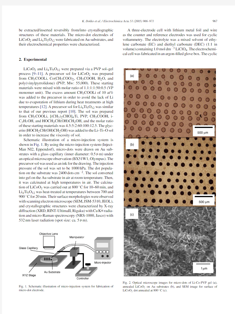
Fig.2.Optical microscope images for micro-dots of Li-Co-PVP gel (a),annealed LiCoO 2on Au substrates (b),and SEM image for surface of LiCoO 2dot annealed at 800?C (c).
968K.Dokko et al./Electrochimica Acta 51(2005)966–971
voltammetry measurements were carried out with a potentio-stat (Model 660B,ALS)at room temperature.
3.Results and discussion 3.1.LiCoO 2micro-dot electrodes
Fig.2a and b display the optical microscope images of micro-dots of Li-Co-PVP gel and LiCoO 2prepared on a gold substrate.The size of a dot was about 100?m in diameter.Fig.2c shows the SEM image of a LiCoO 2dot heat-treated at 800?C for 20min.The surface of the dot was rough,and the grain growth was observed.Fig.3shows the XRD patterns of LiCoO 2micro-dots prepared by heat treatment at 800?C for various durations.The peaks due to Au substrate can be seen at 38.3?and 44.5?.The peaks of LiCoO 2corresponding to the (003),(101),and (104)planes were observed for all samples,and this pattern agrees well to that of previous report [9].The additional peaks were observed at 31.4?and 36.9?,and these were attributed to Co 3O 4generated during heat treatments at high temperatures [13].The Raman spectra of LiCoO 2dots are shown in Fig.4.Raman
measurements
Fig.3.XRD patterns of LiCoO 2micro-dot electrodes fabricated on Au sub-strates annealed at 800?C for 10min (a),20min (b),40min (c),and 60min
(d).
Fig.4.Micro-Raman spectra for LiCoO 2micro-dots annealed at 800?C for 20min.Raman spectra were measured for 25LiCoO 2dots,and 15dots exhibited spectra similar to (a),8dots similar to (b),and 2dots similar to (c).
were carried out for 25LiCoO 2dots.The Raman spectrum of the hexagonal phase (space group:R 3m)with two Raman active modes at 592cm ?1and 482cm ?1arising from E g and A 1g ,respectively [14,15].However,additional Raman peaks at 686and 518cm ?1of an impurity phase were observed for some dots.These peaks originated from Co 3O 4[16].These Raman results are consistent with the results of XRD.The three spectra in Fig.4suggested that the amounts of Co 3O 4in the dots were different from each other,despite the dots were fabricated on the same substrate.In fact,the amount of impurity depended on the heat treatment condition,and the optimized condition to minimize the impurity was annealing at 800?C for 20min.
Fig.5shows the cyclic voltammogram of the LiCoO 2micro-dot electrodes.The cyclic voltammogram was mea-sured for 400dots of LiCoO 2,and the current was divided by the number of dots.The prepared micro-dot electrodes exhibited intrinsic electrochemical properties of the LiCoO 2.The main redox peaks were observed at 3.92and 3.88V versus Li/Li +during anodic and cathodic scan,respectively.Two small redox peaks were also clearly observed at 4.06and 4.16V .These redox peaks are in good agreement with reported ones [9].The Li +ion was deintercalated/intercalated
K.Dokko et al./Electrochimica Acta 51(2005)966–971
969
Fig. 5.Cyclic voltammogram of LiCoO 2micro-dot electrode.Cyclic voltammogram was measured for 400dots of LiCoO 2.Current was nor-malized by both the number of dots and the area of Au substrate.Scan rate was 0.167mV s ?1
.
Fig.6.Optical microscope image for micro-dots of Li 4Ti 5O 12(a),and SEM image for surface of Li 4Ti 5O 12dot on Au substrate annealed at 800?C.from/into the layered structure of Li x CoO 2in the course of anodic scan and cathodic scan,respectively.These redox peaks are correlated with structural changes of Li x CoO 2during intercalation and deintercalation of Li +ions [17].The Co 3O 4is electrochemically inactive in this potential range.The average current for a dot was on the nA level,and the discharge capacity of a LiCoO 2dot calculated from the integration of cathodic current was 14?C.The x in Li x CoO 2was 0.45at 4.2V ,and 14?C corresponded to 2.8×10?11mol of LiCoO 2.The size of a dot is important for designing a micro-battery.In order to control the dot size,viscosity of the precursor sol should be further opti-mized,and modi?cation of the substrate surface may also be effective.
3.2.Li 4Ti 5O 12micro-dot electrodes
Li 4Ti 5O 12micro-dot electrodes were heat-treated at vari-ous temperatures.Fig.6a and b display the optical microscope image and the SEM image of micro-dots of Li 4Ti 5O 12heat-treated at 800?C for 20min,respectively.The typical size of a Li 4Ti 5O 12micro-dot was 100?m in diameter.The Li 4Ti 5O 12dots were very thin and transparent.The surface of Li 4Ti 5O
12
Fig.7.XRD patterns of Li 4Ti 5O 12micro-dot electrodes fabricated on Au substrates annealed at 700?C (a),800?C (b),and 900?C (c)for 20min.
970K.Dokko et al./Electrochimica Acta 51(2005)966–971
was smooth,although there were several micro-cracks in a dot as shown in Fig.6b.XRD patterns of Li 4Ti 5O 12samples are shown in Fig.7.A peak corresponding to (111)plane was observed at 18.5?for all samples.However,the peaks due to impurity phases were detected for the samples prepared at 700and 900?C,and these peaks were attributed to anatase and rutile TiO 2.The Raman spectra of Li 4Ti 5O 12micro-dots prepared at various temperatures are shown in Fig.8.The Raman spectra of the Li 4Ti 5O 12changed depending on the heat treatment temperature.The sample prepared at 700and 900?C showed characteristic peaks of anatase and rutile TiO 2,respectively [18],which agreed well with the results of XRD.The Raman spectrum of the sample annealed at 800?C showed good agreement to that reported by Liu et al.[19],however,the peak due to rutile-TiO 2,which was generated as an impurity,was observed at 614cm ?1.
Fig.9shows the cyclic voltammogram of the Li 4Ti 5O 12micro-dot electrodes prepared at 800?C.The cyclic voltam-mogram was measured for 1000dots of Li 4Ti 5O 12,and the current was divided by the number of dots.The Li 4Ti 5O 12sample showed reversible redox peaks at 1.55V .However,the background currents were observed in both
cathodic
Fig.8.Micro-Raman spectra of Li 4Ti 5O 12micro-dots fabricated on Au substrates annealed at 700?C (a),800?C (b),and 900?C (c)for 20
min.
Fig.9.Cyclic voltammogram of Li 4Ti 5O 12micro-dot electrode.Cyclic voltammogram was measured for 1000dots of Li 4Ti 5O 12.Current was nor-malized by both the number of dots and the area of Au substrate.Scan rate was 0.167mV s ?1.
and anodic scans in the potential range from 2.0to 1.2V .This background was considered due to irreversible reduc-tion of electrolyte components on Au substrate.In the course of the cathodic peak,Li +ion was inserted into Li 4T 5O 12which converted into Li 7Ti 5O 12[20–22].The reversible CV peaks suggest that the Li +ion insertion proceeds reversibly.The discharge capacity of a Li 4Ti 5O 12dot calculated from the integration of anodic current was 1.4?C,which corre-sponded to 4.8×10?12mol of Li 4Ti 5O 12.In spite that the sizes of LiCoO 2dot and Li 4Ti 5O 12dot were similar,the dis-charge capacity of a Li 4Ti 5O 12dot was smaller than that of a LiCoO 2dot.It was considered that the thickness of a Li 4Ti 5O 12dot was thinner than that of LiCoO 2.The opti-mization of the Li–Ti–O sol composition is now underway in order to control the thickness of the dot.
4.Conclusions
Fabrications of micro-dot electrodes of LiCoO 2and Li 4Ti 5O 12on Au substrates were demonstrated using a sol–gel process combined with a micro-injection technol-ogy.The typical size of a prepared dot was about 100?m in diameter,and the dot population on the substrate was 2400dots cm ?2(i.e.20%of the gold was covered by micro-dots).The LiCoO 2micro-dot electrode exhibited reversible electrochemical behavior in a potential range from 3.8to 4.2V versus Li/Li +,and the Li 4Ti 5O 12micro-dot electrode showed sharp redox peaks at 1.55V .
As preliminary experiment,a micro-injection device was utilized in this work to draw the micro-dot patterns of LiCoO 2and Li 4Ti 5O 12.Developments of fabrication tech-niques of micro-battery using ink-jet printing technology are in progress in our group.
K.Dokko et al./Electrochimica Acta51(2005)966–971971
Acknowledgment
This work was partially supported by a Grant-in-Aid for Scienti?c Research(A)(Grant no.14205097)from the Japan Society for the Promotion of Science.
References
[1]P.G.Bruce,https://www.360docs.net/doc/7214508641.html,mun.(1997)1817.
[2]M.Winter,J.O.Besenhard,M.E.Spahr,P.Nov′a k,Adv.Mater.10
(1998)725.
[3]R.Wartena,A.E.Curtright,C.B.Arnold,A.Pique,K.E.Swider-
Lyons,J.Power Sources126(2004)193.
[4]K.Kushida,K.Kuriyama,T.Nozaki,Appl.Phys.Lett.81(2002)
5066.
[5]S.D.Jones,J.R.Akridge,F.K.Shokoohi,Solid State Ionics69(1994)
357.
[6]H.Ohtsuka,Y.Sakurai,Solid State Ionics144(2001)59.
[7]J.B.Bates,N.J.Dudney,B.Neudecker,A.Ueda,C.D.Evans,Solid
State Ionics135(2000)33.
[8]P.Fragnaud,D.M.Schleich,Sens.Actuators A:Phys.51(1995)
21.
[9]Y.H.Rho,K.Kanamura,T.Umegaki,J.Electrochem.Soc.150
(2003)107.
[10]Y.H.Rho,K.Kanamura,J.Electrochem.Soc.151(2004)106.
[11]H.Kozuka,M.Kajimura,T.Hirano,K.Katayama,J.Sol-Gel Sci.
Tech.19(2000)205.
[12]H.Arai,S.Okada,H.Ohtsuka,M.Ichimura,J.Yamaki,Solid State
Ionics80(1995)261.
[13]K.Martin,G.McCarthy,no.42-1467in JCPDS Card,1990.
[14]M.Inaba,Y.Todzuka,H.Yoshida,Y.Grincourt, A.Tasaka,Y.
Tomida,Z.Ogumi,Chem.Lett.(1995)889.
[15]M.Inaba,Y.Iriyama,Z.Ogumi,Y.Todzuka,A.Tasaka,J.Raman
Spectrosc.28(1998)613.
[16]D.L.Rousseau,R.P.Bauman,S.P.S.Porto,J.Raman Spectrosc.10
(1981)253.
[17]J.N.Reimers,J.R.Dahn,J.Electrochem.Soc.139(1992)2091.
[18]G.R.Gu,Y.A.Li,Y.C.Tao,Z.He,J.J.Li,H.Yin,W.Q.Li,Y.N.
Zhao,Vacuum71(2003)487.
[19]D.Z.Liu,W.Hayes,K.Kurmoo,M.Dalton,C.Chen,Physica C
235–240(1994)1203.
[20]T.Ohzuku,A.Ueda,N.Yamamoto,J.Electrochem.Soc.142(1995)
1431.
[21]S.Scharner,W.Weppner,P.Schmid-Beurmannb,J.Electrochem.
Soc.146(1999)857.
[22]K.Kanamura,T.Umegaki,H.Naito,Z.Takehara,T.Yao,J.Appl.
Electrochem.31(2001)73.
常用贴片元件封装尺寸图
常用贴片元件封装尺寸图 目录 1 TO-268AA 41 D-7343 2 TO-26 3 D2PAK 42 C-6032 3 TO-263-7 43 B-3528 4 TO-263- 5 44 A-3216 5 TO-263-3 45 SOT883 6 TO-252 DPAK 46 SOT753 7 TO-252-5 47 SOT666 8 TO252-3 48 SOT663 9 2010 49 SOT552-1 10 4020 50 1SOT523 11 0603 51 SOT505-1 12 0805 52 SOT490-SC89 13 01005 53 SOT457 SC74 14 1008 54 SOT428 15 1206 55 SOT416/SC75 16 1210 56 SOT663 SMD 17 1406 57 SOT363 SC706L 18 1812 58 SOT353/sc70 5L 19 1808 59 SOT346/SC59 20 1825 60 SOT343 SMD 21 2010 61 SOT323/SC70-3 SMD 22 2225 62 SOT233 SMD 23 2308 63 SOT-223/TO-261AA SMD 24 2512 64 SOT89/TO243AA SC62 SMD 25 DO-215AB 65 SOT23-8 26 DO-215AA 66 SOT23-6 27 DO-214AC 67 SOT23-5 28 DO-214AB 68 SOT23 29 DO-214AA 69 SOT143/TO253 SMD 30 DO-214 31 DO-213AB 32 DO-213AA 33 SOD123H 34 SOD723 35 SOD523 36 SOD323 37 SOD-123F 38 SOD123 39 SOD110 40 DO-214AC SOD106
常用元器件封装尺寸大小
封装形式图片国际统一简称 LDCC LGA LQFP PDIP TO5 TO52 TO71 TO71 TO78 PGA Plastic PIN Grid Array 封装形式图片国际统一简称 TSOP Thin Small OUtline Package QFP Quad Flat Package PQFP 100L QFP Quad Flat Package SOT143 SOT220 Thin Shrink Qutline Package uBGA Micro Ball Grid Array uBGA Micro Ball Grid Array PCDIP
PLCC LQFP LQFP 100L TO8 TO92 TO93 T099 EBGA 680L QFP Quad Flat Package TQFP 100L ZIP Zig-Zag Inline Packa SOT223 SOT223 SOT23 SOT23/SOT323 SOT25/SOT353 SOT26/SOT363 FBGA FDIP SOJ
SBGA LBGA 160L PBGA 217L Plastic Ball Grid Array SBGA 192L TSBGA 680L CLCC SC-705L SDIP SIP Single Inline Package SO Small Outline Package SOP EIAJ TYPE II 14L SSOP 16L SSOP SOJ 32L Flat Pack HSOP28 ITO220 ITO3P TO220 TO247
PCB中常见的元器件封装大全参考word
PCB中常见的元器件封装大全 一、常用元器件: 1.元件封装电阻 AXIAL 2.无极性电容 RAD 3.电解电容 RB- 4.电位器 VR 5.二极管 DIODE 6.三极管 TO 7.电源稳压块78和79系列 TO-126H和TO-126V 8.场效应管和三极管一样 9.整流桥 D-44 D-37 D-46 10.单排多针插座 CON SIP 11.双列直插元件 DIP 12.晶振 XTAL1 电阻:RES1,RES2,RES3,RES4;封装属性为axial系列 无极性电容:cap;封装属性为RAD-0.1到rad-0.4 电解电容:electroi;封装属性为rb.2/.4到rb.5/1.0 电位器:pot1,pot2;封装属性为vr-1到vr-5 二极管:封装属性为diode-0.4(小功率)diode-0.7(大功率) 三极管:常见的封装属性为to-18(普通三极管)to-22(大功率三极管)to-3(大功率达林 顿管) 电源稳压块有78和79系列;78系列如7805,7812,7820等;79系列有7905,7912,7920等.常见的封装属性有to126h和to126v 整流桥:BRIDGE1,BRIDGE2: 封装属性为D系列(D-44,D-37,D-46) 电阻:AXIAL0.3-AXIAL0.7 其中0.4-0.7指电阻的长度,一般用AXIAL0.4 瓷片电容:RAD0.1-RAD0.3。其中0.1-0.3指电容大小,一般用RAD0.1 电解电容:RB.1/.2-RB.4/.8 其中.1/.2-.4/.8指电容大小。一般<100uF用RB.1/.2,100uF-470uF用RB.2/.4,>470uF用RB.3/.6 二极管:DIODE0.4-DIODE0.7 其中0.4-0.7指二极管长短,一般用DIODE0.4 发光二极管:RB.1/.2 集成块:DIP8-DIP40, 其中8-40指有多少脚,8脚的就是DIP8
常用贴片元件封装尺寸图
目录 TO-268AA贴片元件封装形式图片 (3) TO-263 D2PAK封装尺寸图 (4) TO-263-7封装尺寸图 (5) TO-263-5封装尺寸图 (6) TO-263-3封装尺寸图 (7) TO-252 DPAK封装尺寸图 (8) TO-252-5封装尺寸图 (9) TO252-3封装尺寸图 (10) 0201封装尺寸 (11) 0402封装尺寸图片 (12) 0603封装尺寸图 (13) 0805封装尺寸图 (14) 01005封装尺寸图 (15) 1008封装尺寸图 (16) 1206封装尺寸图 (17) 1210封装尺寸图 (18) 1406封装尺寸图 (19) 1812封装尺寸图 (20) 1808封装尺寸图 (21) 1825封装尺寸图 (22) 2010封装尺寸图 (23) 2225封装尺寸图 (24) 2308封装尺寸图 (25) 2512封装尺寸图 (26) DO-215AB封装尺寸图 (27) DO-215AA封装尺寸图 (28) DO-214AC封装尺寸图 (29) DO-214AB封装尺寸图 (30) DO-214AA封装尺寸图 (31) DO-214封装尺寸图 (32) DO-213AB封装尺寸图 (33) DO-213AA封装尺寸图 (34) SOD123H封装图 (35) SOD723封装尺寸图 (36) SOD523封装尺寸图 (37) SOD323封装尺寸图 (38) SOD-123F封装尺寸图 (39) SOD123封装尺寸图 (40) SOD110封装尺寸图 (41) DO-214AC SOD106封装尺寸图 (42) D-7343封装尺寸图 (43)
(整理)常用PCB封装图解
常用集成电路芯片封装图 doc文档可能在WAP端浏览体验不佳。建议您优先选择TXT,或下载源文件到本机查看。 PCB 元件库命名规则2.1 集成电路(直插)用DIP-引脚数量+尾缀来表示双列直插封装尾缀有N 和W 两种,用来表示器件的体宽N 为体窄的封装,体宽300mil,引脚间距2.54mm W 为体宽的封装, 体宽600mil,引脚间距 2.54mm 如:DIP-16N 表示的是体宽300mil,引脚间距2.54mm 的16 引脚窄体双列直插封装 2.2 集成电路(贴片)用SO-引脚数量+尾缀表示小外形贴片封装尾缀有N、M 和W 三种,用来表示器件的体宽N为体窄的封装,体宽150mil,引脚间距 1.27mm M 为介于N 和W 之间的封装,体宽208mil,引脚间距1.27mm W 为体宽的封装, 体宽300mil,引脚间距 1.27mm 如:SO-16N 表示的是体宽150mil,引脚间距1.27mm 的16 引脚的小外形贴片封装若SO 前面跟M 则表示为微形封装,体宽118mil,引脚间距0.65mm 2.3 电阻 2.3.1 SMD 贴片电阻命名方法为:封装+R 如:1812R 表示封装大小为1812 的电阻封装2.3.2 碳膜电阻命名方法为:R-封装如:R-AXIAL0.6 表示焊盘间距为0.6 英寸的电阻封装 2.3.3 水泥电阻命名方法为:R-型号如:R-SQP5W 表示功率为5W 的水泥电阻封装 2.4 电容 2.4.1 无极性电容和钽电容命名方法为:封装+C 如:6032C 表示封装为6032 的电容封装 2.4.2 SMT 独石电容命名方法为:RAD+引脚间距如:RAD0.2 表示的是引脚间距为200mil 的SMT 独石电容封装 2.4.3 电解电容命名方
最新SMT常见贴片元器件封装类型和尺寸资料
1、SMT表面封装元器件图示索引(完善)
2、SMT物料基础知识 一. 常用电阻、电容换算: 1.电阻(R): 电阻:定义:导体对电流的阻碍作用就叫导体的电阻。 无方向,用字母R表示,单位是欧姆(Ω),分:欧(Ω)、千欧(KΩ)、兆欧(MΩ)1MΩ=1000KΩ=1000000Ω 1).换算方法: ①.前面两位为有效数字(照写),第三位表示倍数10n次方(即“0”的个数) 103=10*103=10000Ω=10KΩ 471=47*101=470Ω 100=10*100=10Ω 101=10×101=100Ω 120=12×100=12Ω ②.前面三位为有效数字(照写),第四位表示倍数倍数10n次方(即“0”的个数). 1001=100*101=1000Ω=1KΩ 1632=163*102=16300Ω=16.3KΩ 1470=147×100=147Ω 1203=120×103Ω=120KΩ 4702=470×102Ω=47KΩ
2.电容(C): 电容的特性是可以隔直流电压,而通过交流电压。它分为极性和非极性,用C表示。 2.1三种类型:电解电容钽质电容有极性, 贴片电容无极性。 用字母C表示,单位是法(F),毫法(MF),微法(UF),纳法(NF)皮法(PF) 1F=103MF=106UF=109NF=1012PF 2.2换算方法: 前面两位为有效数字(照写),第三位倍数10n次方(即“0”的个数) 104=10*104=100000PF=0.1UF 100=10*100=10PF 473=47×103=47000pF=47nF=0.047uF 103=10×103=10000pF=10nF=0.01uF 104=10×104=100000pF=10nF=0.1uF 221=22×101=220pF 330=33×100=33pF 2.3钽电容: 它用金属钽或者铌做正极,用稀流酸等配液做负极,用钽或铌表面生成的氧化膜做成介质制成,其特点是体积小、容量大、性能稳定、寿命长、绝缘电阻大、温度特性好,用在要求较高的设备中。钽电容表面有字迹表明其方向、容值,通常有一条横线的那边标志钽电容的正极。钽电容规格通常有:A型、B型、C型、P型。 2.4 电容的误差表示 2.4.1常用钽电容代换参照表. 1UF:105、A6、CA6 2.2UF:225 3.3UF:335、AN6、CN6、JN6、CN69 4.7UF:475、JS6 10UF:106、JA7、AA7、GA7 22UF:226、GJ7、AJ7、JJ7 47UF:476 3. 电感(L)
常用元件库及原器件封装
常用的原理图符号 一、“Miscellaneous Devices.DDB”原理图符号库,该原理图符号库中包含了常用的普通元器件,如电阻、电容、二极管、三极管、开关及插接件等。 二、Protel DOS Schematic Libraries.lib原理图符号库,该原理图符号库中主要包含的是集成电路芯片,如CMOS,TTL数字集成电路芯片,AD,DA芯片,比较器,放大器微处理器芯片以及存储器芯片等。Protel DOS Schematic Libraries.lib原理图符号库包含14个子库。 1.Protel DOS Schematic 4000CMOS.lib原理图符号库,该原理图 符号库主要包含4000系列的CMOS数字集成芯片。 (4011,4013,4023,4043,4052等) 2.Protel DOS Schematic Analog digital.lib原理图符号库,该原理 图符号库主要包含AD,DA芯片。(DAC0800,ADC0800等)3.Protel DOS Schematic Comparator.lib原理图符号库,该原理 图符号库主要包含比较器芯片。(LM193,CA139,TL331,LF111等) 4.Protel DOS Schematic Intel.lib原理图符号库,该原理图符号 库主要包含Intel公司生产的微处理芯片。(8031,8051,8755等) 5.Protel DOS Schematic Linear.lib原理图符号库,该原理图符号 库主要包含一些线性原件。(555,4N25,LM135H等)
6.Protel DOS Schematic Memory.lib原理图符号库,该原理图符 号库主要包含一些存储芯片。(6164,2716,27128等) 7.Protel DOS Schematic Motorola.lib原理图符号库,该原理图 符号库主要包含Motorola公司生产的一些元器件 (6800,68701,8T26等) 8.Protel DOS Schematic NEC.lib原理图符号库,该原理图符号 库主要包含NEC公司生产的一些元器件(UPD7800, MC430P,UPD550等) 9.Protel DOS Schematic Operational Amplifiers.lib原理图符号 库,该原理图符号库主要包各类运算放大器芯片。(LM741,LM1458,TL084等) 10.Protel DOS Schematic Synertek.lib原理图符号库,该原理 图符号库主要包含Synertek公司生产的一些元器件 (SY64CX13,SY65C51,SYE6522等) 11.Protel DOS Schematic TTL.lib原理图符号库,该原理图符号 库主要包含74系列数字集成电路芯片。 (74ALS00,74HC73,74F373等) 12.Protel DOS Schematic Voltage.lib原理图符号库,该原理图 符号库主要包各类线性稳压块 (LM79L05ACZ,LM109H,LM7812CK等) 13.Protel DOS Schematic Western.lib原理图符号库,该原理图 符号库主要包含Western公司生产的一些元器件(FD1771,
常见元件的封装形式.
常见元件的封装形式 对于集成电路芯片来说,常见的封装形式有DIP(即双列直插式),根据封装材料的不同,DIP封装又可以分为PDIP(塑料双列直插式)和CDIP(陶瓷双列直插式); SIP(即单列直插式);SOP(即小尺寸封装);PQFP(塑料四边引脚扁乎封装);PLCC(塑料有引线芯片载体封装)和LCCC(陶瓷无引线芯片载体封装);PGA(插针网格阵列)、BGA(球形网格阵列)等。对于具体型号的集成电路芯片来说,其封装形式是固定的,如74系列集成电路芯片,一般采用DIP 封装形式,只有个别芯片生产厂家提供两种或两种以上封装形式。 对于分立元件(如电阻、电容、电感)来说,元件封装尺寸与元件大小、耗散功率、安装方式等因素有关。 1.电阻器常用的封装形式 电阻器常用的封装形式是AXIALO·3~AXIALl·0,对于常用的1/81r小功率电阻来说,可采用AXlALO·3或AXIALO·4(即两引线孔间距为0·762~1·016cm):对于1/4W电阻来说,可采用AXlALO·5(即两引线孔间距为1·27cm),但当采用竖直安装时,可采用AXlALO·3。 2.小容量电解电容的封装形式 小容量电解电容的封装形式一般采用RB·2/.4(两引线孔距离为0·-2英寸,而外径为0.4英寸)到RB.5/1·0(两引线孔距离为O·5英寸,而外径为1·0英寸)。对于大容量电容,其封装尺寸应根据实际尺寸来决定。 3.普通二极管封装形式 普通二极管封装形式为DIODEO·4~DIODEO·7。 4.三极管的封装形式 三极管的封装形式由三极管型号决定,常见的有T0-39、T0-42、T0-54、TO-92A、TO-92B、T0-220等。 对于小尺寸设备,则多采用表面安装器件,如电阻、电容、电感等一股采用SMC线封装方式;对于三极管、集成电路来说,多采用SMD封装方式。 进行电原理图编辑和印制板设计时,器件型号完全确定后,可以从器件手册查到封装形式和尺寸,或测绘后用PCBLib编辑器创建元件的封装图。 当用户实在无法确定时,也可以在PCB编辑器窗口内,单击元件“放置工具",再 单击“测览”按钮,从Advpcb·ddb元件封装图形库中找出所需元件的封装形式。
贴片元器件封装尺寸
【SMD贴片元件的封装尺寸】 公制:3216——2012——1608——1005——0603——0402 英制:1206——0805——0603——0402——0201——01005 注意: 0603有公制,英制的区分 公制0603的英制是英制0201, 英制0603的公制是公制1608 还要注意1005与01005的区分, 1005也有公制,英制的区分 英制1005的公制是公制2512 公制1005的英制是英制0402 像在ProtelDXP(Protel2004)及以后版本中已经有SMD贴片元件的封装库了,如 CC1005-0402:用于贴片电容,公制为1005,英制为0402的封装 CC1310-0504:用于贴片电容,公制为1310,英制为0504的封装 CC1608-0603:用于贴片电容,公制为1608,英制为0603的封装 CR1608-0603:用于贴片电阻,公制为1608,英制为0603的封装,与CC16-8-0603尺寸是一样的,只是方便识别。 【贴片电阻规格、封装、尺寸】 英制(inch) 公制 (mm) 长(L) (mm) 宽(W) (mm) 高(t) (mm) a (mm) b (mm) 0201 0603 0.60±0.05 0.30±0.05 0.23±0.05 0.10±0.05 0.15±0.05 0402 1005 1.00±0.10 0.50±0.10 0.30±0.10 0.20±0.10 0.25±0.10 0603 1608 1.60±0.15 0.80±0.15 0.40±0.10 0.30±0.20 0.30±0.20 0805 2012 2.00±0.20 1.25±0.15 0.50±0.10 0.40±0.20 0.40±0.20 1206 3216 3.20±0.20 1.60±0.15 0.55±0.10 0.50±0.20 0.50±0.20 1210 3225 3.20±0.20 2.50±0.20 0.55±0.10 0.50±0.20 0.50±0.20 1812 4832 4.50±0.20 3.20±0.20 0.55±0.10 0.50±0.20 0.50±0.20 2010 5025 5.00±0.20 2.50±0.20 0.55±0.10 0.60±0.20 0.60±0.20 2512 6432 6.40±0.20 3.20±0.20 0.55±0.10 0.60±0.20 0.60±0.20 国内贴片电阻的命名方法:
常用贴片元件封装
常用贴片元件封装 1 电阻: 最为常见的有0201、0402、0805、0603、1206、1210、1812、2010、2512几类1)贴片电阻的封装与尺寸如下表: 英制(mil) 公制(mm) 长(L)(mm) 宽(W)(mm) 高(t)(mm) 0201 0603 ±±± 0402 1005 ±±± 0603 1608 ±±± 0805 2012 ±±± 1206 3216 ±±± 1210 3225 ±±± 1812 4832 ±±± 2010 5025 ±±± 2512 6432 ±±± 2)贴片电阻的封装、功率与电压关系如下表: 英制(mil)公制(mm)额定功率@ 70°C 最大工作电压(V) 0201 0603 1/20W 25 0402 1005 1/16W 50 0603 1608 1/10W 50 0805 2012 1/8W 150 1206 3216 1/4W 200 1210 3225 1/3W 200 1812 4832 1/2W 200 2010 5025 3/4W 200 2512 6432 1W 200 3)贴片电阻的精度与阻值 贴片电阻阻值误差精度有±1%、±2%、±5%、±10%精度, J -表示精度为5%、 F-表示精度为1%。 T -表示编带包装 阻值范围从0R-100M 4)贴片电阻的特性 ·体积小,重量轻; ·适应再流焊与波峰焊; ·电性能稳定,可靠性高; ·装配成本低,并与自动装贴设备匹配; ·机械强度高、高频特性优越。 2电容: 1)贴片电容可分为无极性和有极性两种,容值范围从 无极性电容下述两类封装最为常见,即0805、0603; 英制尺寸公制尺寸长度宽度厚度 0402 1005 ± ± ± 0603 1608 ± ±±
常用贴片元件封装.
常用贴片元件封装 1 电阻: 最为常见的有 0201 、040 2 、 0805 、060 3 、1206 、 1210 、1812 、2010 、2512 几类 1)贴片电阻的封装与尺寸如下表: 英制(mil)公制(mm)长(L)(mm)宽(W)(mm) 高(t)(mm) 英制(mil)公制(mm)额定功率@ 70 C 最大工作电压(V) 0201 0603 1/20W 25 0402 1005 1/16W 50 0603 1608 1/10W 50 0805 2012 1/8W 150 **** **** 1/4W 200 1210 3225 1/3W 200 1812 4832 1/2W 200 0201 0603 0.60 ±0.05 0.30 ±0.05 0.23 ±0.05 0402 1005 1.00 ±0.10 0.50 ±0.10 0.30 ±0.10 0603 1608 1.60 ±0.15 0.80 ±0.15 0.40 ±0.10 0805 2012 2.00 ±0.20 1.25 ±0.15 0.50 ±0.10 1206 3216 3.20 ±0.20 1.60 ±0.15 0.55 ±0.10 1210 3225 3.20 ±0.20 2.50 ±0.20 0.55 ±0.10 1812 4832 4.50 ±0.20 3.20 ±0.20 0.55 ±0.10 2010 5025 5.00 ±0.20 2.50 ±0.20 0.55 ±0.10 2512 6432 6.40 ±0.20 3.20 ±0.20 0.55 ±0.10 功率与电压关系如下表: 2)贴片电阻的封装、
贴片元件常见封装
贴片电阻常见封装有9种,用两种尺寸代码来表示。一种尺寸代码是由4位数字表示的EIA(美国电子工业协会)代码,前两位与后两位分别表示电阻的长与宽,以英寸为单位。我们常说的0603封装就是指英制代码。另一种是米制代码,也由4位数字表示,其单位为毫米。下表列出贴片电阻封装英制和公制的关系及详细的尺寸:
一、零件规格: (a)、零件规格即零件的外形尺寸,SMT发展至今,业界为方便作业,已经形成了一个标准零件系列,各家零件供货商皆是按这一标准制造。 标准零件之尺寸规格有英制与公制两种表示方法,如下表 英制表示法1206 0805 0603 0402 公制表示法3216 2125 1608 1005 含义 L:1.2inch(3.2mm)W:0.6inch(1.6mm) L:0.8inch(2.0mm)W:0.5inch(1.25mm) L:0.6inch(1.6mm)W:0.3inch(0.8mm) L:0.4inch(1.0mm)W:0.2inch(0.5mm) 注: a、L(Length):长度;W(Width):宽度;inch:英寸 b、1inch=25.4mm (b)、在(1)中未提及零件的厚度,在这一点上因零件不同而有所差异,在生产时应以实际量测为准。 (c)、以上所讲的主要是针对电子产品中用量最大的电阻(排阻)和电容(排容),其它如电感、二极管、晶体管等等因用量较小,且形状也多种多样,在此不作讨论。 (d)、SMT发展至今,随着电子产品集成度的不断提高,标准零件逐步向微型化发展,如今最小的标准零件已经到了0201。 二、常用元件封装 1)电阻: 最为常见的有0805、0603两类,不同的是,它可以以排阻的身份出现,四位、八位都有,具体封装样式可参照MD16仿真版,也可以到设计所内部PCB库查询。