GDCB变频器故障
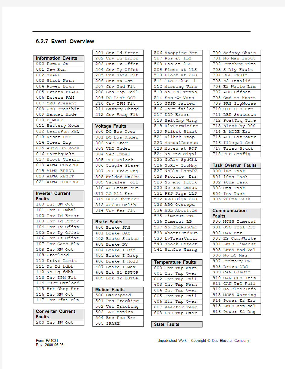
6.2.7 Event Overview
Information Events 000 Power On
001 New Run
002 SPARE
003 Stack Warn 004 Power Down 005 Extern FLASH 006 Extern RAM 007 OMU Present 008 OMU Prohibit 009 Manual Mode 010 B_MODE
011 Battery Mode 012 LearnRun REQ 013 Reset DSP
014 Clear Log
015 AutoTun Mode 016 Earthquake 017 Block Cleard 018 ALWA CONVRGD 019 ALWA ERROR 020 ALWA RESET 021 ALWA DIVERGD Inverter Current Faults
100 Inv SW Oct 101 Inv I Imbal 102 Inv Id Error 103 Inv Iq Error 104 Inv Ix Offst 105 Inv Iy Offst 106 Inv Iz Offst 107 Inv Gate Flt 108 Inv HW Oct 109 Overload
110 Drive Limit 111 No Id fdbk 112 No Iq fdbk 113 Inv IPM Flt 114 Curr Ovrload 115 Brk Chop Err 116 Inv HW Ovt 117 Inv Pfai Flt Converter Current Faults
200 Cnv SW Oct 201 Cnv Id Error
202 Cnv Iq Error
203 Cnv Ix Offst
204 Cnv Iy Offst
205 Cnv Gate Flt
206 Cnv HW Oct
207 Cnv Gnd Flt
208 Bus Cap Fail
209 DC Link OCT
210 Cnv IPM Flt
211 Battry Chrgd
212 Cnv Vmag Flt
Voltage Faults
300 DC Bus Over
301 DC Bus Under
302 VAC Over
303 VAC Under
304 VAC Imbal
305 PLL Unlock
306 Single Phase
307 PLL Freq Rng
308 Welded Mx/Px
309 Vscales off
310 AC Brown-out
311 AC All Err
312 DBTR ShrtErr
313 AC/DC Calib
314 Cnv Res Flt
Brake Faults
400 Brake SAS
401 Brake SAS
402 Brake Status
403 Brake BY
404 Brake I Off
405 Brake I Drop
406 Brake I Hold
407 Brake I Max
408 Brk S1 ESTOP
409 Brk S2 ESTOP
Motion Faults
500 Overspeed
501 Pos Tracking
502 Vel Tracking
503 LRT Motion
504 Enc Pos Err
505 SPARE
506 Stopping Err
507 Pos at 1LS
508 Pos at 2LS
509 Floor at 1LS
510 Floor at 2LS
511 1LS & 2LS !
512 Missing Vane
513 No PRS Trans
514 Enc <> Vane
515 NTSD failed
516 Corr failed
517 DDP Error
518 BeltCmp Wrng
519 RlvPermitErr
520 Rllbck Start
521 Rllbck Stop
522 ManualRescue
523 Moved at POF
524 No Enc Signl
525 NoRlv SpdChk
526 NoRlv TooMny
527 NoRlv LostDZ
528 Profile Err
529 No enc fdbck
530 No enc tmout
531 PRS Sigs 1LS
532 PRS Sigs 2LS
533 ARO Overspd
534 ABL Abort:LW
535 Timeout PTR
536 Timeout LB
537 No EndRunCmd
538 Abort:EndRun
539 LvTransUnclr
540 Shock Detect
541 SinCos Warng
Temperature Faults
600 Inv Tmp Warn
601 Inv Tmp Over
602 Inv Tmp Fail
603 Cnv Tmp Warn
604 Cnv Tmp Over
605 Cnv Tmp Fail
606 Mtr Tmp Over
607 Reactor Temp
608 DBR Tmp Over
State Faults
700 Safety Chain
701 No Man Input
702 Prechrg Time
703 S Rly Fault
704 DBD Fault
705 E2 Invalid
706 E2 Write Lim
707 ADC Offset
708 Cmd to Abort
709 PRS SigNoise
710 UIB DIB Err
711 DBD Shutdown
712 PostTrq Time
713 Block by 000
714 B_MODE Err
715 ARO BatPower
716 Illegal Cmd
717 Triac Stuck
718 PRS Config
Task Overrun Faults
800 1ms Task
801 10ms Task
802 40ms Task
803 Cnv Task
804 Inv Task
805 200ms Task
Communication
Faults
900 MCSS Timeout
901 SVC Tool Err
902 CAN Err
903 E2 CommWrite
904 LWSS Timeout
905 LWSS Bad Val
906 No LS Msg
907 Primary CRC
908 Drive CRC
909 CAN BusOff
910 CAN OPB_Init
911 CAN TxQ Full
912 No FloorInfo
913 MCSS Warning
914 Power E2 Err
915 LWSS not cal
916 Power E2 Rng
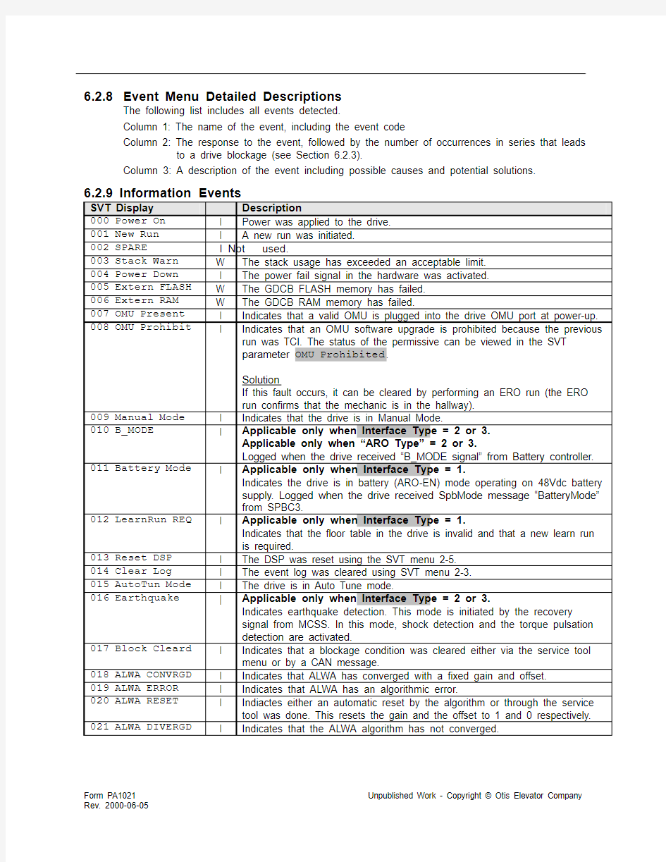
6.2.8 Event Menu Detailed Descriptions
The following list includes all events detected.
Column 1: The name of the event, including the event code
Column 2: The response to the event, followed by the number of occurrences in series that leads to a drive blockage (see Section 6.2.3).
Column 3: A description of the event including possible causes and potential solutions.
6.2.9 Information Events
SVT Display Description
000 Power On I Power was applied to the drive.
001 New Run I A new run was initiated.
002 SPARE I Not
used.
003 Stack Warn W The stack usage has exceeded an acceptable limit.
004 Power Down I The power fail signal in the hardware was activated.
005 Extern FLASH W The GDCB FLASH memory has failed.
006 Extern RAM W The GDCB RAM memory has failed.
007 OMU Present I Indicates that a valid OMU is plugged into the drive OMU port at power-up. 008 OMU Prohibit I Indicates that an OMU software upgrade is prohibited because the previous
run was TCI. The status of the permissive can be viewed in the SVT
parameter OMU Prohibited.
Solution
If this fault occurs, it can be cleared by performing an ERO run (the ERO
run confirms that the mechanic is in the hallway).
009 Manual Mode I Indicates that the drive is in Manual Mode.
010 B_MODE I Applicable only when Interface Type = 2 or 3.
Applicable only when “ARO Type” = 2 or 3.
Logged when the drive received “B_MODE signal” from Battery controller. 011 Battery Mode I Applicable only when Interface Type = 1.
Indicates the drive is in battery (ARO-EN) mode operating on 48Vdc battery
supply. Logged when the drive received SpbMode message “BatteryMode”
from SPBC3.
012 LearnRun REQ I Applicable only when Interface Type = 1.
Indicates that the floor table in the drive is invalid and that a new learn run
is required.
013 Reset DSP I The DSP was reset using the SVT menu 2-5.
014 Clear Log I The event log was cleared using SVT menu 2-3.
015 AutoTun Mode I The drive is in Auto Tune mode.
016 Earthquake | Applicable only when Interface Type = 2 or 3.
Indicates earthquake detection. This mode is initiated by the recovery
signal from MCSS. In this mode, shock detection and the torque pulsation
detection are activated.
017 Block Cleard I Indicates that a blockage condition was cleared either via the service tool
menu or by a CAN message.
018 ALWA CONVRGD I Indicates that ALWA has converged with a fixed gain and offset.
019 ALWA ERROR I Indicates that ALWA has an algorithmic error.
020 ALWA RESET I Indiactes either an automatic reset by the algorithm or through the service
tool was done. This resets the gain and the offset to 1 and 0 respectively. 021 ALWA DIVERGD I Indicates that the ALWA algorithm has not converged.
6.2.10 Inverter Current Faults
SVT Display Description
100 Inv SW Oct E4 The magnitude of the inverter current exceeded an allowed threshold.
Possible Causes & Solutions
?Incorrect motor phasing → change parameter Motor Phase 0/1.
?Shorted motor phase → check motor wiring continuity.
?The fault threshold can be temporarily adjusted by the parameter
Inv I Limit %.
Applicable when Interface Type = 0 or 1:
OCT(A) = Drive I fullscale * Inv I Limit %* 0.9 * 1.05
(Drive I fullscale: 402? 80A 404?110A)
Applicable when Interface Type = 2 or 3:
OCT(A) = Drive I fullscale * Inv I Limit %* 0.9 * 1.25
101 Inv I Imbal E4 The sum of the three motor currents exceeded 10% full-scale current.
Possible Causes & Solutions
? Ground fault → check there are no motor phases shorted to ground.
? Signal noise → check that wiring guidelines are followed.
102 Inv Id Error 103 Inv Iq Error E4 The indicated inverter current regulator error exceeded an allowable threshold.
Possible Causes & Solutions
?Current regulators are not tuned correctly → check proper motor parameter settings (see Section 9).
104 Inv Ix Offst 105 Inv Iy Offst 106 Inv Iz Offst E The indicated inverter phase current offset exceeded 5% of full-scale.
Possible Causes & Solutions
? Defective circuit → change drive package (if occurs permanently).
107 Inv Gate Flt E4 NOT applicable when Drive Type is 25A.
An inverter IGBT gate supply voltage fault was detected.
Possible Causes & Solutions
?Defective or shorted gate power supply → change drive package (if
occurs permanently).
108 Inv HW Oct E4 NOT applicable when Drive Type is 25A.
For 60A V.2 - drives:
The power section has detected a fault and set the discrete input
(ERR1/INV_FLT: P1-12 ) to the GDCB. Because this input is shared
by both HW Overcurrent and HW Overvoltage errors, the measured
DC bus voltage is used to distinguish between them:
- DC bus voltage is below a specified threshold
--> this fault was declared.
- DC bus voltage is above a specified threshold
--> 116 Inv HW Ovt would have been declared.
For all other drives except the 25A drive:
The inverter current exceeded a preset level, detected via hardware,
(ERR1/INV_FLT: P1-12 ) to the GDCB.
Possible Causes & Solutions
?Incorrect motor phasing → change parameter Motor Phase 0/1.
?Shorted motor phase → check motor wiring continuity.
109 Overload E4 An overload condition has been detected. The drive exceeded the
maximum time allowed operating at the rated current of the motor.
Possible Causes & Solutions
?Excessive friction in system → check for dragging brake or hoistway
interference.
?The drive is undersized for the installed duty → confirm system inertia.
?The fault threshold can be adjusted by the parameters: Overload
sec, Rated mtr i Arms, and Rated Acc I PU, but should not be
increased by more than 10%.
110 Drive Limit W The drive is operating at its rated current limit.
111 No Id fdbk 112 No Iq fdbk E4 An error has been detected with the current feedback of the inverter during magnetization of the motor at the beginning of the run.
Possible Causes & Solutions
?Open motor phase → check motor wiring continuity.
?Bad current sensor → return unit for service.
See parameters Vd out thresh PU and Vq out thresh PU.
113 Inv IPM Flt E4 Applicable only when Drive Type is 25A.
Inicates a fault has been detected from the inverter Intelligent Power
Module (IPM).
Possible Causes & Solutions
?Defective or shorted gate power supply → change drive package (if
occurs permanently).
?Incorrect motor phasing → change parameter Motor Phase 0/1.
?Shorted motor phase → check motor wiring continuity.
114 Curr Ovrload E4 Not used (was applicable only for non-regen drives).
115 Brk Chop Err E4 Not used (was applicable only for non-regen drives).
116 Inv HW Ovt E4 Applicable only for 60A V.2 drives.
The power section has detected a fault and set the discrete input
(ERR1/INV_FLT: P1-12 ) to the GDCB. Because this input is shared by
both HW Overcurrent and HW Overvoltage errors, the measured DC bus
voltage is used to distinguish between them:
- DC bus voltage is above a specified threshold
--> this fault was declared.
- DC bus voltage is below a specified threshold
--> 108 Inv HW Oct would have been declared.
117 Inv Pfai Flt E4 Applicable only for 60A V.2 drives.
Inverter PWM activity has been detected during IDLE (when S1 & S2 are
dropped):
?after 2 seconds in IDLE the inverter PWM driver was still active;
?or after 4 seconds in IDLE the signal PF_IGBT: P1-13 was LOW which
indicated a still active IGBT power supply although it should be
switched OFF.
Possible Causes & Solutions
?Defective gate driver or power supply → change drive package (if
occurs permanently).
6.2.11 Converter Current Faults
SVT Display Description
200 Cnv SW Oct E4 The magnitude of the converter current exceeded an allowed threshold.
Possible Causes & Solutions
? Defective hardware → change drive package (if occurs permanently).
?The fault threshold can be temporarily adjusted by the parameter
Cnv I Limit %.
Applicable when Interface Type = 0 or 1:
OCT(A) = Drive I fullscale * Cnv I Limit %* 0.9 * 1.05
(Drive I fullscale: 402? 80A 404?110A)
Applicable when Interface Type = 2 or 3:
OCT(A) = Drive I fullscale * Cnv I Limit %* 0.9 * 1.25
201 Cnv Id Error
E4 The indicated converter current error exceeded 30% of full-scale.
202 Cnv Iq Error
Possible Causes & Solutions
?Current regulators are not tuned correctly → check proper parameter
settings (see parameter Cnv Custom 0/1).
203 Cnv Ix Offst
E The indicated converter phase current offset exceeded 5% of full-scale. 204 Cnv Iy Offst
Possible Causes & Solutions
? Defective circuit → change drive package (if occurs permanently).
205 Cnv Gate Flt E4 NOT applicable when Drive Type is 25A.
An inverter IGBT gate supply voltage fault was detected.
Possible Causes & Solutions
?Defective or shorted gate power supply → change drive package (if
occurs permanently).
206 Cnv HW Oct E4 NOT applicable when Drive Type is 25A.
The converter current exceeded a preset level, detected via hardware.
Possible Causes & Solutions
? Defective hardware → change drive package (if occurs permanently). 207 Cnv Gnd Flt S Applicable only when Drive Type is 60A.
A ground fault was detected on the converter.
Possible Causes & Solutions
? Ground fault → disconnect drive from utility power and check that there
are no phases shorted to ground.
208 Bus Cap Fail S The estimated power loss in the drive exceeded a limit. This indicates that
excessive power is being dissipated in the drive and is a strong indication
that a DC link capacitor has failed. The threshold for this fault is set bt the
SVT parameters Ploss Thr pre %, Ploss Thr idle %, and Ploss
Thr run %
209 DC Link OCT S Applicable only when Drive Type is 40A.
Indicates excessive DC link current.
Possible Causes & Solutions
?Shorted motor phase → check motor wiring continuity.
? Ground fault → disconnect drive from utility power and check that there
are no phases shorted to ground.
210 Cnv IPM Flt E4 Applicable only when Drive Type is 25A.
Inicates a fault has been detected from the converter Intelligent Power
Module (IPM).
Possible Causes & Solutions
?Defective or shorted gate power supply → change drive package (if
occurs permanently).
?Defective IPM hardware → change drive package (if occurs
permanently).
? Ground fault → disconnect drive from utility power and check that there
are no phases shorted to ground.
211 Battry Chrgd E4 Applicable only during ARO (EN) mode.
The drive detected charging current into the battery during ARO, which is
not allowed. The threshold for the charging currenmt is controlled by the
parameter Max Bat Chrg I A.
212 Cnv Vmag Flt E4 This fault occurs when the converter voltage command magnitude is
greater than a level specified by the parameter Cnv Vmag Thrs PU. This
fault management is active only when the drive is regenerating and only
when the nominal AC line voltage parameter AC Main Vrms is set <=
400. This fault management is not active when Low Volt Op 0/1 is set to 1.
6.2.12 Voltage Faults
SVT Display Description
300 DC Bus Over E3 The DC bus voltage was greater than 108% of the nominal bus voltage of
750 VDC.
301 DC Bus Under E6 The DC bus voltage exceeded a limit. The limits are:
For 415 < Vac <= 480, limit = 70% of nominal (750).
For 380 <= Vac <= 415, limit = 309 Vdc.
For Vac < 380, limit = 70% of nominal (750).
The nominal ac voltage is determined by the EEPROM parameter: AC
Main Vrms.
302 VAC Over C The AC line voltage exceeded a limit. The limits are:
For 415 < Vac <= 480, limit = 112% of nominal.
For 380 <= Vac <= 415, limit = 477 Vrms.
For Vac < 380, limit = 115% of nominal.
The nominal voltage is determined by the EEPROM parameter: AC Main
Vrms.
303 VAC Under C The AC line voltage exceeded a limit. The limits are:
For 415 < Vac <= 480, limit = 85% of nominal.
For 380 <= Vac <= 415, limit = 323 Vrms.
For Vac < 380, limit = 85% of nominal.
The nominal voltage is determined by the EEPROM parameter: AC Main
Vrms.
304 VAC Imbal C The AC line input voltages differ from each other by more than 10%.
305 PLL Unlock E The phase lock loop on the AC input voltage has unlocked. This is likely to
occur when you try to run with a damaged IGBT.
This fault sets the SAS flag.
306 Single Phase S This fault is declared when the drive is set to single-phase mode, and the T
phase is connected to a live input. The power during single-phase
operation should be connected to R and S phases only and the T-phase
should be left open. See EEPROM parameter: Single Phase 0/1
307 PLL Freq Rng E This fault is declared when the drive ac line frequency estimate is outside
of a frequency band specified by the parameter PLL freq band Hz for a
amount of time specified by the parameter PLL freq time ms, while
there is no PLL unlock fault. This fault is logged whenever the AC line is
disconnected. Repeated logging may be an indication of a problem with the
AC line.
308 Welded Mx/Px S When the drive enters the power down state, if the DC Bus voltage does
not drop below a voltage threshold within a (drive-type depending) wait
time, the system will declare that the MX and/or PX contacts may be
welded.
Warning:
Do not cycle power to drive until fault is verified.
Check the “Inp:Vrms Vdc” SVT display to verify whether the Vdc is
actually stuck to a high value (1.41 times the Vrms value) while the state of
MX and PX in the “MX PX DX BX” SVT display is actually “0”. If these
conditions are met (high Vdc and “0” for both MX and PX), then DO NOT
ATTEMPT TO CYLE POWER TO THE DRIVE. This drive may have a real
welded MX or PX condition that needs to addressed. For this condition,
power down, lock out/tag out energy source, and ship drive back to factory. 309 Vscales off W This fault is logged when the measured AC line voltage and measured DC
bus voltage disagree significantly. This check is performed only after M1 is
picked after the bus has had enough time to settle to its quiescent value.
This fault may indicate that either of the following EEPROM parameters is
not set correctly: DC Bus fscale V, AC Line fscale V.
310 AC Brown-out W Applicable only for Interface Type 1.
This warning indicates that the ac line has dropped 15% below the nominal
value. When the ac line drops 30% below nominal, 303 VAC Under fault is
logged. The drive will continue to run under the "Brown Out" event with
reduced motion profiles. However, in case of “303 VAC Under”, the drive
will finish the current run and not accept any further runs.
311 AC All Err E This fault can occur for one of two reasons:
1. The AC line voltage exceeded a limit above the 302 VAC Over threshold.
The limits are:
For 415 < Vac <= 480, limit = 125% of nominal.
For 380 <= Vac <= 415, limit = 519 Vrms.
For Vac < 380, limit = 125% of nominal.
The nominal voltage is determined by the EEPROM parameter: AC Main
Vrms.
OR
2. The following three faults occur at the same time while PTR is active:
302 VAC Over AND
304 VAC Imbal AND
307 PLL Freq Rng
312 DBTR ShrtErr C Applicable only for ARO Type=NIARO (JIS) and Generator Mode.
This fault is set for detecting the short of DBTR.
When using a generator, set Generator Mode for 1.
When using NIARO mode, set ARO Type for 3.
Check DBTR if it has broken.
313 AC/DC Calib I Applicable only when Low Volt Op 0/1 = 1.
This fault is active only in low voltage operation mode. This indicates that
the calibration process ac voltage sensor versus dc voltage sensor resulted
with a cross calibration factor that is either larger than 1.5 or less than 0.5. 314 Cnv Res Flt E This fault management is active only when the event 304 VAC Imbal is
active. This fault occurs when a converter voltage transient occurs that
exceeds a threshold that is at least 25% greater than the AC Main Vrms
parameter setting. If this fault occurs, then check that the 3 phase AC input
is present and is reasonably balanced.
6.2.13 Brake Faults
SVT Display Description
400 Brake SAS 401 Brake SAS C4 The indicated brake switch is in the wrong state. This is checked both when the drive is in the Idle state and when the drive is running.
These faults result in complete the run fault response and set the SAS
flag.
Note: this event is also applicable when Brk Switch 0 - 4 is set to 0 or 4
where constant states are required on BS1 and BS2 inputs.
Possible Causes & Solutions
?Incorrect parameter value → verify correct value of Brk Switch 0 - .
?Incorrect brake switch wiring → check brake switch wiring.
?Brake not lifting → check brake wiring & brake power supply.
?Insufficient time allowed → see parameters Brk Pick Time ms and Brk Setl Time ms.
402 Brake Status E4 Applicable only when Internal Brk 0/1 is set to 0.
The brake status feedback from the brake module is not in the correct
state.
403 Brake BY E4 Applicable only when Internal Brk 0/1 is set to 0.
One or both of the normally-closed BY contacts are not in the correct
state. The BY relays should be energized when PTR is active, before the
lift brake command is initiated.
Possible Causes & Solutions
?Incorrect wiring to brake module → check brake module wiring.
?Incorrect brake power supply → check brake power supply & wiring.
?Adjust SVT parameter: SX Pick Time ms
404 Brake I Off E4 Applicable only when Internal Brk 0/1 is set to 1.
When using the internal brake control, this fault is logged when the brake
current feedback offset compensation exceeds the asmount specified by
the parameter Brk I Offset A.
405 Brake I Drop E4 Applicable only when Internal Brk 0/1 is set to 1.
When the internal brake control drops the brake, this fault is logged if the
brake current feedback exceeds a threshold specified by the service tool
parameter Brk I Hold A.
406 Brake I Hold E4 Applicable only when Internal Brk 0/1 is set to 1.
When the internal brake control picks the brake, this fault is logged if the
brake current feedback is less than a threshold specified by the service
tool parameter Brk I Hold A.
407 Brake I Max E4 Applicable only when Internal Brk 0/1 is set to 1.
This fault is logged if the internal brake control current feedback exceeds
a threshold specified by the service tool parameter Brk I Max A.
408 Brk S1 ESTOP 409 Brk S2 ESTOP E4 The indicated brake switch is in the wrong state. This is checked both when the drive is in the Idle state and when the drive is running.
These faults result in an immediate ESTOP and set the SAS flag.
Note: this event is also applicable when Brk Switch 0 - 4 is set to 0 or 4
where constant states are required on BS1 and BS2 inputs.
Possible Causes & Solutions
?Incorrect parameter value → verify correct value of Brk Switch 0 - .
?Incorrect brake switch wiring → check brake switch wiring.
?Brake not lifting → check brake wiring & brake power supply.
Insufficient time allowed → see parameters Brk Pick Time ms and Brk Setl Time ms.
6.2.14 Motion Faults
SVT Display Description
500 Overspeed E4 The motor speed has exceeded a speed threshold. The speed threshold
is determined by the operating mode of the drive:
MCSS mode: adjustable perecentage of Duty Speed mm/s
Manual Mode: adjustable percentage of Man Speed mm/s
CAN Normal: 110% of Duty Speed mm/s
CAN Relevel: fixed percentage of max relevel = 20 mm/sec
CAN Learn: fixed percentage of max learn = 500 mm/sec
CAN ERO/TCI: fixed percentage of Insp Speed mm/s
CAN Rescue: fixed percentage of max rescue = 300 mm/sec
For MCSS and manual modes, the percentage is adjusted by SVT
parameters: MCSS Overspeed % and MAN Overspeed %.
501 Pos Tracking E4 The position tracking error exceeded a threshold and indicates that the
position feedback was not tracking the position reference from the profile
generator. This fault is checked only when the drive uses its internal
profile generator. See EEPROM parameter: Pos Err Lim mm
502 Vel Tracking E4 The velocity tracking error exceeded a threshold. The velocity feedback
was not tracking the velocity reference.
Possible Causes & Solutions
?Incorrect motor phasing → change parameter Motor Phase 0/1.
?Wrong encoder feedback → check encoder wiring and attachment.
?Incorrect parameter value → verify correct value of Inertia kg-m2.
?Excessive start jerk / improper pre-torque → verify load weigh
device; if no load weigh device present (as during inspection), try
increasing parameter Start Gain Ot PU. See section 4.11 for further
instruction.
?Brake not lifting → check brake wiring & brake power supply.
? Hoistway obstructed → check for obstruction (e.g. car or
counterweight on buffer).
?The fault threshold can be adjusted by parameter Track Error mm/s.
When Manual Mode is active, this fault threshold is automatically
increased by a factor of 3.
503 LRT Motion E4 This fault indicates motion was detected while performing the Locked
Rotor Test. The Locked Rotor Test is performed at the beginning of the
first run after a power-up to determine the position of the magnets when
using a PM motor. The threshold for the fault is specified by the
parameter LRT mot err eDeg. If the fault occurs, the brake may not be
set properly.
504 Enc Pos Err W This fault indicates that the drive has lost track of the magnet position
when using a PM motor. This fault is necessary to prevent a loss of
torque production. This fault may be caused by the encoder physically
slipping with respect to the motor, or by a bad magnet position
calculation during the locked rotor test (LRT).
This fault is detected by comparing the magnet position, derived from the
encoder and the result of the LRT, to the estimated magnet position
based on the back-EMF of the motor. Since the estimator is back-EMF
based, the fault detection is enabled only when the motor operates
above 30% of the rated motor speed. The default threshold for the fault
is 20 electrical degrees. Another locked rotor test will be performed at the
beginning of the next run to automatically re-determine the magnet
position.
See EEPROM parameter: Mag err thr eDeg
See EEPROM parameter: Rated Motor rpm
See display parameter: Mag Pos Err eDeg
505 SPARE D Not
used.
506 Stopping Err W A time-out occurred because the stopping criteria at the end of the run
were not satisfied. See EEPROM parameters: Pos Stop Tol mm
and Vel Stop mm/sec
507 Pos at 1LS D Applicable only for Interface Type 1.
Unexpected position at 1LS. The 1LS transition occurred at a position
outside the expected range for 1LS, or the 1LS signal state is not
consistent with hoistway position. Applicable only when landing table is
valid and position is valid.
508 Pos at 2LS D Applicable only for Interface Type 1.
Unexpected position at 2LS. The 2LS transition occurred at a position
outside the expected range for 2LS, or the 2LS signal state is not
consistent with hoistway position. Applicable only when landing table is
valid and position is valid.
509 Floor at 1LS D Applicable only for Interface Type 1.
Unexpected floor at 1LS. The 1LS transition occurred at a floor that is
different from the expected floor. Applicable only when landing table is
valid and limit switch signals are valid.
510 Floor at 2LS D Applicable only for Interface Type 1.
Unexpected floor at 2LS. The 2LS transition occurred at a floor that is
different from the expected floor. Applicable only when landing table is
valid and limit switch signals are valid.
511 1LS & 2LS ! D Applicable only for Interface Type 1.
Both LS signals are valid and active simultaneously.
512 Missing Vane D3 Applicable only for Interface Type 1.
Expected vane is missing. Logged only when outside a vane and an
expected transition onto a vane has not occurred. Not checked in
Inspection or Correction runs.
513 No PRS Trans D3 Applicable only for Interface Type 1.
Expected transition is missing. Logged only when on a vane and an
expected transition has not occurred. Not checked in Inspection or
Correction runs.
514 Enc <> Vane D3 Applicable only for Interface Type 1.
An unexpected vane transition occurred. Possible causes could be:
1. Incorrect Car Dir 0/1 setting.
2. Wrong Vane Sensor Type parameter setting.
3. PRS sensor signal wiring mistake.
4. PRS is having false transitions.
5. Encoder is not firmly attached to rotor.
6. Magnet has moved since it was learned during the learn run.
7. Belts are slipping or creeping over the drive sheave excessively.
8. Belts are stretching excessvely.
515 NTSD failed W Applicable only for Interface Type 1.
During a normal run, the normal stopping profile did not decelerate the
car in time to meet the target. The timed-decel is two-phased, containing
a creep region. Only triggered at the terminal landings. The condition for
triggering the fault is that the normal profile overshoots the target
compared to a linear ramp-down of the speed at 110% of normal decel
rate. Only triggered above a certain speed (presently 0.1 m/s).
516 Corr failed D Applicable only for Interface Type 1.
A correction run missed the target. This fault is triggered when a
correction run terminates outside of the limit switches or outside a vane,
or at a different landing other than the terminal landing. The fault is
logged after the car has stopped.
Note: There is a minor bug with the SVT display for this fault. The fault
response in the SVT is shown as ESTOP, when it is actually DECEL. 517 DDP Error E1 Applicable only for Interface Type 1.
Delayed Drive Protection (DDP) fault. The time between vanes has
exceeded a specified value. It is not checked during learn, ERO, or TCI
runs. The fault is cleared only by a power cycle or software reset of the
drive. The time is specified by the EEPROM parameter: DDP sec.
This fault sets the SAS flag.
518 BeltCmp Wrng W Applicable only for Interface Type 1.
This indicates that the compensation factors for belt and traveling cable
imbalance determined during the learn run were exceptionally large
(specifically, the offset factor was greater than 25% rated torque). The
compensation factors can be viewed in the SVT display: BeltCmp:Slp
mA/m, BeltCmp:Offset A.
519 RlvPermitErr W Applicable only when Interface Type is 1 and Load Weigh Type is 1.
Controller has given permissive to relevel while load weighing system
indicates overload condition. This contradictory situation has persisted
for >200ms.
520 Rllbck Start W Applicable only for Interface Type 1.
Rollback of more than 5.0 mm at beginning of run
521 Rllbck Stop W Applicable only for Interface Type 1.
Rollback (reverse to direction of run) or overshoot (in direction of run) of
more than 5.0 mm at ending of run
522 ManualRescue D Applicable only for Interface Type 1.
SPBC message reports that the car has been moved for manual rescue
(drive powered off, SPBC lifts brake). The drive’s stored position is
invalidated and a locked rotor test initiated before the next run.
523 Moved at POF W Applicable only for Interface Type 1.
The SPBC or GECB and the drive have contradictory position
information (at power up): the SPBC’s or GECB’s position has been
assumed by the drive.
524 No Enc Signl E Applicable only when Encoder Type 0/1 is set to 0 (incremental,
double-ended).
Encoder channel A input is not detected. Encoder may not be connected,
encoder power supply may have failed, or encoder may have failed.
This fault sets the SAS flag.
525 NoRlv SpdChk D1Relevel speed is too high (>= 0.285 m/s).
526 NoRlv TooMny D1Attempt to relevel after 20 consecutive relevel runs have been performed
without start of normal run.
527 NoRlv LostDZ D1Lost DZ signal or detecting UIS/DIS signal disagreeing with mm-position
(on opposite side of target mm-position).
528 Profile Err W The profile chosen is not compatible with the system environment:
A) The LS1 or LS2 lengths (learned during learn run) are too short for
the drive to be able to stop within. This can be caused by too large
speeds in the profile setting or too small deceleration entered. The
other possibility would be a really short LS magnet. Cause A can be
identified in the vane monitor M-1-7 by comparing measured LS to
minimum required.
B) The Nom Speed is set too high for the LS signal latency reported by
the ICD of the GECB/TCBC (e.g. Nom Speed > 1.8m/s with TCBC).
This setting could lead to CORR runs not reaching the target vane. 529 No enc fdbck E4 This fault indicates that the motor started moving without an encoder.
This fault is triggered when the motor voltage exceeds a certain
threshold defined by No Enc VThrs PU while the encoder speed
feedback is below 1mm/s. Check the integrity of the encoder. Also,
check motor parameters.
530 No enc tmout E4 This fault indicates that the drive started commanding velocity profile and
the motor speed feedback did not exceed 1mm/s for the time duration
defined by the parameter No enc flt t sec (default value of the parameter
is 0.4 secs). This fault detection is not active in Manual Mode.
Possible Causes & Solutions
?No encoder feedback signal → check encoder wiring and
mechanical attachment to the sheave.
?Incorrect parameter value → verify correct value of Inertia kg-m2,
Man Acc mm/s2, Accel mm/s2, or any of the acceleration
parameters in the (L)MCSS if operating in 422 mode.
?Excessive start jerk / improper pre-torque → verify load weigh
device; if no load weigh device present (as during inspection), try
increasing parameter Start Gain Ot PU. See section 4.11 for further
instruction.
?Brake not lifting → check brake wiring & brake power supply.
? Hoistway obstructed → check for obstruction (e.g. car or
counterweight on buffer).
?The fault threshold can be adjusted by parameter No enc flt t sec 531 PRS Sigs 1LS D Applicable only for Interface Type 1.
The transition into 1LS occurred with PRS signals that are not expected
near the learned LS transition point. Applicable only when landing table
is valid and limit switch signals are valid.
532 PRS Sigs 2LS D Applicable only for Interface Type 1.
The transition into 2LS occurred with PRS signals that are not expected
near the learned LS transition point. Applicable only when landing table
is valid and limit switch signals are valid.
533 ARO Overspd E Applicable only when Interface Type = 2 or 3.
Applicable only when “ARO Type” = 2 (Interruptable ARO).
This fault is declared when the motor speed has exceeded a speed
threshold set by the parameter ARO Overspeed % as a percentage of
ARO Speed mm/s. This fault is disabled with ARO Overspeed % =0. If
this fault is logged, the run is immediately terminated by the drive.
534 ABL Abort:LW ER Applicable only for Interface Type 1.
A command for advanced brake lift was received and ignored because
no valid load data was available.
535 Timeout PTR ERS Applicable only for Interface Type 1.
While in state “Prepare To Run” (during Advanced Brake Lift), the drive
did not receive a command to leave this state and timed out after 60s. 536 Timeout LB ERS Applicable only for Interface Type 1.
While in state “Lift Brake” (during Advanced Brake Lift), the drive did not
receive a command to leave this state and timed out after 16s.
537 No EndRunCmd ERS Applicable only for Interface Type 1.
While waiting for a DriveCommand EndRun in substate “STOPPED” the
drive did not receive this command and timed out after 3s..
538 Abort:EndRun ER Applicable only for Interface Type 1.
The run has been terminated with normally profiled deceleration by an
OPB command (DriveCommand EndRun)..
539 LvTransUnclr D3 Applicable only for Interface Type 1.
With a single-sensor PRS, an ambiguous sensor transition has been
detected, could have been either one of two vane edges. Potential root
cause: Uncertain mm-position (ESTOP sliding, Power Up recovery from
GECB/SPBC, position recovery in LS) and transition occurs within first
5mm of travel.
540 Shock Detect W Applicable only for Interface Type 2 or 3.
The shock condition was detected for REI/REM and EAR.
541 SinCos Warng W This fault will be logged for one of the following conditions:
1. When using a CEIB and sin/cos encoder
A. If any of the analog encoder signals fail when using the CEIB, then
this fault will be logged.
B. If the Encoder Type 0/1 SVT parameter has the wrong setting of
"0", then this fault will be logged.
2. When using an incremental encoder without a CEIB
If the Encoder Type 0/1 SVT parameter has the wrong setting of
"1", then this fault will be logged.
1) This Timed Deceleration reaction does not lead to the SHUTDOWN state
6.2.15 Temperature Faults
SVT Display Description
600 Inv Tmp Warn W The temperature of the inverter heat sink has exceeded 80C.
601 Inv Tmp Over C1 The temperature of the inverter heat sink has exceeded 85C. The fault
detection includes hysteresis, and will not clear until the temperature of
the heat sink drops 5C below fault value.
602 Inv Tmp Fail C1Indicates the analog temperature sensor on the inverter heat sink is not
connected or has failed. The fan will turn on and remain on when this
condition is detected.
603 Cnv Tmp Warn W The temperature of the converter heat sink has exceeded 80C.
604 Cnv Tmp Over C1The temperature of the converter heat sink has exceeded 85C. The fault
detection includes hysteresis, and will not clear until the temperature of
the heat sink drops 5C below fault value.
605 Cnv Tmp Fail C1Indicates the analog temperature sensor on the converter heat sink is not
connected or has failed. The fan will turn on and remain on when this
condition is detected.
606 Mtr Tmp Over C1The motor thermal contact has changed state indicating that either the
motor is overheating or there is a problem with the contact circuitry.
Check the motor temperature and the thermal contact. Although motor
thermal contacts can be normally open or normally closed, the drive
always expects a normally closed contact. If the thermal contact is
normally open, a modification must be made to adapt it to the drive.
607 Reactor Temp C1The thermal switch in the line reactor has opened, indicating an over-
temperature condition in the line reactor.
608 DBR Tmp Over C1Not used (was applicable only for non-regen drives).
1) When these temperature faults occur in 422 mode, PTR is not accepted until the fault condition
clears. When these temperature faults occur in CAN mode, the drive behaves as follows:
1. Normal runs are re-routed to the next committable landing.
2. Inspection runs (TCI+ERO) are terminated by timed deceleration.
3. All other runs (ARO, CORR, Rescue, MRO, Relevel) are completed to their regular end
4. No new run is allowed until the condition clears.
5. The fan is turned on 100%.
6.2.16 State Faults
SVT Display Description
700 Safety Chain E/
W The safety chain is not present. The opening of the safety chain will cause SX relays to drop, causing the drive to de-energized the motor and brake, thus causing an ESTOP.
?For 422 system, the response is ESTOP
?For CAN system, the response is LOG ONLY
Note: Due to switch timing variation, this event can be logged sporadically when switching from NORMAL to ERO/TCI (no problem in unit)
701 No Man Input E Applicable only for Interface Type 0.
This fault occurs if the drive is in manual mode and the manual mode
jumper is removed.
702 Prechrg Time E3 This fault is declared when the DC bus fails to reach the charge voltage
threshold within a time limit. The time limit is approximately 2 seconds for
60A V.2 drives and 10 seconds for other regen drives. The timer starts
when the drive enters the precharge state.
For MCSS systems, the drive enters the powerdown state and waits 2
minutes, and then attempts again. For the regen drive, further precharge
attempts are made only if the AC line voltage is within specification. There
is no limit on the number of precharge attempts.
For CAN systems, the drive enters the powerdown state and waits 30
seconds, and then attempts again. For the regen drive, further precharge
attempts are made only if the AC line voltage is within specification. There
is a limit of 3 consequtive precharge timeouts after which the drive will be
blocked.
The voltage threshold is 80% of the actual rectified AC line voltage.
Note: There is a minor bug with the SVT display for this fault. The fault
response in the SVT is shown as WARN, when it is actually ESTOP.
703 S Rly Fault E4 The normally-open S1 contact was in the wrong state.
See SVT parameter SX Pick Time ms.
704 DBD Fault E4 One or more of the normally-closed contacts of S1, S2, BY1 and BY2
were in the wrong state. Three attempts are allowed before the drive is
blocked.
See SVT parameter SX Pick Time ms.
705 E2 Invalid E The data in the EEPROM is set to values incompatible with the current
SCN or new EEPROM parameters have not yet been set. The invalid or
blank values must be corrected. Pressing SHIFT_ENTER tells which
parameter is invalid and what menu it is located.
706 E2 Write Lim W The allowable number of writes to the EEPROM have been exceeded:
Metric writes: 100,000 maximum
Event writes: 1,000,000 maximum
707 ADC Offset C The ADC offset variance is greater than the 2.9% of the ADC full scale, or
the ADC gain variance is greater than 6.5%. There may be a problem with
the analog circuitry. The fault is checked only when drive state <= IDLE.
This fault sets the SAS flag and sends the drive state to SHUTDOWN until
the fault clears.
See SVT parameter: ADC:gain% offset
708 Cmd to Abort D Applicable only for Interface Type 1.
The run has been terminated with timed deceleration by an OPB
command (DriveRunCommand dir=none). This fault does NOT result in
SHUTDOWN.
709 PRS SigNoise D Applicable only for Interface Type 1.
Too many PRS signal transitions have occurred over a fixed period of
time.
710 UIB DIB Err E Applicable only for Interface Type 1.
The UIB and DIB inputs were not consistent with the run command from
TCBC-type controller. This fault sets the SAS flag.
711 DBD Shutdown S Three attempts were made to try to correct a relay in the wrong state (one
or more of the normally-closed contacts of S1, S2, BY1 and BY2 were in
the wrong state). The drive is blocked from further runs.
712 PostTrq Time W A log only fault is reported when the current is not ramped down to zero
within a specified time.
713 Block by 000 S The drive has been blocked from further runs. This occurs after certain
critical faults have been detected, indicated by “S” in this table, or when
certain faults have exceeded an allowed number of occurrences, indicated
in this table by the number that follows the fault response category. The
blockage must be cleared following the guidelines in Section 6.2.3.
This fault sets the SAS flag.
714 B_MODE Err W Applicable only when Interface Type = 2 or 3.
Applicable only when “ARO Type” = 3 (NIARO).
This fault is logged when “B_MODE” was not detected in less than 200ms
from the time when the drive received some fault of "201 Cnv Id Error/ 202
Cnv Iq Error/208 Bus Cap Fail/305 PLL Unlock" or detected DC Bus
voltage less than 650V.
715 ARO BatPower D Applicable only in CAN-architecture. The power drawn from the battery
during an MRO/ARO run was too high, e.g. > 15A * 48V for 800ms.
716 Illegal Cmd W Applicable only for Interface Type 1 with systems using GECB
where CarController ICD >= 10, see “CAN ICD type” in M-1-8 ENGINEERING.
An unexpected command has been received in a state where it could not
be executed. It was ignored. Note it is possible that a GECB command
coincides with a state change in the drive making execution of that
command impossible. In such a case, this warning does not indicate a
problem with the system.
717 Triac Stuck E Applicable only for Interface Type 1.
This fault is logged if both triacs are disabled and safety chain feedback is
in the active state. It is not checked during ARO(EN) runs.
718 PRS Config C Applicable only for Interface Type 1.
This fault indicates illegal configuration of the PRS. Causes (see M-3-2):
?“offset mm” for a sensor is outside “Vane Length mm”
(<- Test Variable 2 = 1)
?no DZ configured, i.e. "LV1 config 0/1/2"=0 and "LV2 config
0/1/2"=0, (<- Test Variable 2 = 2)
?gap between 2 sensors configured <5mm or sequence of sensor
positions violated. Required sequence UIS > LV1 > LV2 > DIS
6.2.17 Task Overrun Faults
SVT Display Description
800 1ms Task S The 1 ms task overran. Contact Enigineering.
801 10ms Task S The 10 ms task overran. Contact Enigineering.
802 40ms Task S The 40 ms task overran. Contact Enigineering.
803 Cnv Task S The Converter task overran. Contact Enigineering.
804 Inv Task S The Inverter task overran. Contact Enigineering.
805 200ms Task S The 200ms Task Overran. Contact Enigineering.
6.2.18 Communication Faults
SVT Display Description
900 MCSS Timeout E Applicable only for Interface Type 0.
Valid MCSS communication has not been received for 80 msecs.
901 SVC Tool Err W Service tool communication error detected via the local service tool port. 902 CAN Err W Applicable only for Interface Type 1.
CAN communication error detected.
903 E2 CommWrite W An error occurred when writing to the EEPROM device.
904 LWSS Timeout W Applicable only for Interface Type 1 and Load Weigh Type is set to
1 or 2. The drive has not received a loadweigh message within a certain
time. The fault is cleared when a valid LW message is received.
905 LWSS Bad Val W Applicable only for Interface Type 1 and Load Weigh Type is set to
1 or 2. The drive received an erroneous value in the loadweigh message.
Load Weigh Type = 1 :
The drive received the full scale value for load percent from the LWB2.
The load percent value can be checked in the SVT menu of the LWB2.
Load Weigh Type = 2 :
The drive received the full scale value for the hitch load measured in kg
from the Hitch LW device. The value can be checked in the menu Monitor-
Motion, it is the first value in the display “ HitchLW: Empty: “
The fault is cleared when a valid LW message is received.
906 No LS Msg D Applicable only for Interface Type 1.The drive has not receieved the
DriveHoistwaySignal message for 3 seconds.
907 Primary CRC W The drive application performs a CRC of the primary loader and this value
does not match the value computed by the conversion utility.
908 Drive CRC S The drive application performs a CRC of the drive software and this value
does not match the value computed by the conversion utility.
909 CAN BusOff W Applicable only for Interface Type 1.
The CAN controller of the drive has shut itself down due to a persistent
communication problem on the CAN bus or CAN power failure (broken
connection).
910 CAN OPB_Init W Applicable only for Interface Type 1.
Initialization of the CAN communication software has failed.
911 CAN TxQ Full W Applicable only for Interface Type 1. Overflow in the transmit queue of
the CAN port, messages have been lost.
912 No FloorInfo W Applicable only for Interface Type 1. Neither the SPBC nor the GECB
have sent valid position in return to the request by the drive (timeout
200ms after request for SPBC, 200ms after its StartUp message for
GECB).
913 MCSS Warning W Applicable only for Interface Type 0.
MCSS Communication error detected. It includes Checksum, Framing,
Parity or invalid format.
914 Power E2 Err W1 The power section could not be identified, because either the E2 in the
power section could not be read or the data was corrupt. The check is
only perform at power on. If active, the drive will not advance past the Init
state.
915 LWSS not cal W Applicable only when Interface Type = 1.
Applicable only when Load Weigh Type = 2.
Hitch load weighing device not calibrated. The calibration is done during a
learn run.
916 Power E2 Rng W Applicable only to drives with eI2C EEPROM storage capability.
This fault is logged if the scaling parameters in one of the power section
EEPROMs are out of range for the specified drive type.
普传变频器故障大全
一、普传变频器故障——上电后键盘无显示 1、检查输入电源是否正常,若正常,可测量直流母线p、n端电压是否正常:若没电压,可断电检查充电电阻是否损坏断路; 2、经查p、n端电压正常,可更换键盘及键盘线,如果仍无显示,则需断电后检查主控板与电源板连接的26p排线是否有松脱现象或损坏断路; 3、若上电后开关电源工作正常,继电器有吸合声音,风扇运转正常,仍无显示,则可判定键盘的晶振或谐振电容坏,此时可更换键盘或修理键盘; 4、如果上电后其它一切正常,但仍无显示,开关电源可能未工作,此时需停电后拔下p、n端电源,检查ic3845的静态是否正常(凭经验进行检查),如果ic3845静态正常,此时在p、n加直流电压后18v/1w稳压二极管两端约8v左右的电压,但开关电源并未工作,断电检查开关变压器副边的整流二极管是否有击穿短路; 5、上电后18v/1w稳压二极管有电压,仍无显示,可除去外围一些插线,包括继电器线插头、风扇线插头,查风扇、继电器是否有短路现象; 6、p、n端上电后,18v/1w稳压二极管两端电压为8v左右,用示波器检查ic3845的输入端④脚是否有锯齿波,输出端⑥脚是否有输出; 7、检查开关电源的输出端+5v、±15v、+24v及各路驱动电源对地以及极间是否有短路。 二、普传变频器故障——键盘显示正常,但无法操作 1、若键盘显示正常,但各功能键均无法操作,此时应检查所用的键盘与主控板是否匹配(是否含有ic75179),对于带有内外键盘操作的机器,应检查一下所设置的拨码开关位置是否正确; 2、如果显示正常,只是一部分按键无法操作,可检查按键微动开关是否不良。 三、普传变频器故障——电位器不能调速 1、首先检查控制方式是否正确; 2、检查给定信号选择和模拟输入方式参数设置是否有效; 3、主控板拨码开关设置是否正确; 4、如果以上均正确,则可能是电位器不良,应检查阻值是否正常。 四、普传变频器故障——过流保护(oc) 1、当变频器键盘上显示“fooc”时“oc”闪烁,此时可按“∧”键进入故障查询状态,可查到故障时运行频率、输出电流、运行状态等,可根据运行状态及输出电流的大小,判定其“oc”保护是负载过重保护还是vce保护(输出有短路现象、驱动电路故障及干扰等); 2、若查询时确定由于负载较重造成加速上升时电流过大,此时适当调整加速时间及合适的v/f特性曲线; 3、如果没接电机,空运行变频器跳“oc”保护,应断电检查igbt是否损坏,检查igbt的续流二极管和ge间的结电容是否正常。若正常,则需检查驱动电路:检查驱动线插接位置是否正确,是否有偏移,是否虚插;检查是否是因hall 及线不良导致“oc”;检查驱动电路放大元件(如ic33153 等)或光耦是否有短路现象;检查驱动电阻是否有断路、短路及电阻变
变频器常见故障分析及维修对策
变频器在我厂水泵上的应用 邓涛 唐山三友化工股份公司电仪车间 摘要本文从实际出发,结合在实际应用中遇到的问题,介绍和分析了变频器在水泵应用上常见的几种故障现象以及解决方法,并分析变频器在水泵上节能效果,对于电气技术人员及时判断、处理水泵变频器运行中出现的故障和水泵电机节能计算上有所帮助。 关键词水泵负载变频器故障跳车节能降耗 引言 水泵在我厂属于较普遍的负载,水泵负载的大小通常以所输送的液体流量为控制参数,通常以阀门控制和转速控制来调节水泵负载的大小。 1水泵的作用 水泵通常用来提升液体、输送液体或使液体增加压力 , 即把原动机的机械能变为液体能量从而达到抽送液体目的。 衡量水泵性能的技术参数有流量、吸程、扬程、轴功率、水功率、效率等;根据不同的工作原理可分为容积水泵、叶片泵等类型。容积泵是利用其工作室容积的变化来传递能量;叶片泵是利用回转叶片与水的相互作用来传递能量,有离心泵、轴流泵和混流泵等类型。 2变频器水泵负载常见的故障及处理方法 电机的最大功率必须满足负载下的机械功率和转矩,对于不同的负载,最大值并非时时刻刻都发生,负载的变化是非线性的,而电机的输出功率却是恒定的,这就意味着在非最大负载时电机输出了相当一部分多余功率,电能也就白白浪费掉了。水泵类就是较典型的例子 水泵的负载性质是平方递减转矩型,有下列关系:水泵的流量Q与转速n成正比;扬程H与转速n的三次方成正比;电动机的转速n与电源频率F成正比.因此改变电动机电源频率,可改变电机即水泵的转速,从而达到调节给水流量和水泵的扬程的目的。
由于水泵中液体流量是不停变化的,所以变频器故障多为一下几种。 2.1 电源故障 对于电源故障,包括电源接触器故障,输入、输出缺相,外部设备故障。维修时应检查外部控制回路及各个元器件以及变频器输入、输出配线,输入电压和电机电缆等。 2.2直流过电压 直流过电压多出现在变频器减速的过程中,当水泵负载惯性较大,变频器虽已“减速”,但水泵电机由于负载的较大惯性而继续运转,此时电机处于发电状态,它将向变频器回馈电能,并向电容器充电,造成变频器直流电压过高,变频器跳车。 解决方法:首先查看变频器的参数表,如果减速时间过短,则延长减速时间,看实际运行效果如何;如果在某一时间段还经常出现直流过电压现象,则考虑使用外部制动单元,进行能耗制动,效果明显,但需增加费用。 2.3运行过电流 变频器加减速过电流,恒速运行过电流。这种情况往往由于加减速设定的时间太短,变频器功率太小,电源电压低以及负载异常引起。处理时应检查具体参数设定及所拖动负载是否正常。 2.4模块保护 由于异常情况的发生可能引起变频器内部保护动作。包括:瞬间过流、输出侧短路或接地,由于风道堵塞或散热风机损坏,致使功率模块散热器过热、整流桥散热器过热等原因造成温度过高,插件松动,控制板异常等情况。可根据不同变频器的具体情况做出更换或修复等相应处理。 2.5 电机过载 过载故障包括变频过载和电机过载。其可能是加速时间太短,电网电压太低、负载过重等原因引起的。一般可通过延长加速时间、延长制动时间、检查电网电压等。负载过重,所选的电机和变频器不能拖动该负载,也可能是由于机械润滑不好引起。如前者则必须更换大功率的电机和变频器;如后者则要对
变频器过流故障的原因及处理方法
变频器中过电流保护的对象主要指带有突变性质的、电流的峰值超过了过电流检测值(约额定电流的200%),变频器显示OC表示过电流,由于逆变器件的过载能力较差,所以变频器的过电流保护是至关重要的一环。 变频器过流故障的原因分析 过电流故障可分为加速、减速、恒速过电流。其可能是由于变频器的加减速时间太短、负载发生突变、负荷分配不均,输出短路等原因引起的。这时一般可通过延长加减速时间、减少负荷的突变、外加能耗制动元件、进行负荷分配设计、对线路进行检查等来解决。如果断开负载变频器还是过流故障,说明变频器逆变电路已坏,需要更换变频器。根据变频器显示,可从以下几方面寻找原因: (1)工作中过电流,即拖动系统在工作过程中出现过电流。其原因大致有以下几方面: l 一是电动机遇到冲击负载或传动机结构出现“卡住”现象,引起电动机电流的突然增加; l 二是变频器输出侧发生短路,如输出端到电动机之间的连接线发生相互短路,或电动机内部发生短路等、接地(电机烧毁、绝缘劣化、电缆破损而引起的接触、接地等) l 三是变频器自身工作不正常,如逆变桥中同一桥臂的两个逆变器件在不断交替的工作过程中出现异常。如环境温度过高,或逆变器元器件本身老化等原因,使逆变器的参数发生变化,导致在交替过程中,一个器件已经导通,而另一个器件却还未来得及关断,引起同一个桥臂的上、下两个器件的“直通”,使直流电压的正、负极间处于短路状态。 (2)升速、降速时过电流:当负载的惯性较大,而升速时间或降速时间又设定得太短时,也会引起过电流。在升速过程中,变频器工作频率上升太快,电动机的同步转速迅速上升,而电动机转子的转速因负载惯性较大而跟不上去,结果是升速电流太大;在降速过程中,降速时间太短,同步转速迅速下降,而电动机转子因负载的惯性大,仍维持较高的转速,这时同样可以使转子绕组切割磁力线的速度太大而产生过电流。 变频器过流故障的处理方法 (1)起动时一升速就跳闸,这是过电流十分严重的现象,主要检查: l 工作机械有没有卡住;
高压变频器的工作原理和常见故障分析 贾瑟
高压变频器的工作原理和常见故障分析贾瑟 摘要:随着现代科学技术的迅速发展,大量的发电企业正在使用着高压变频器。高压变频器在使用过程中具有显著的节能效果,但也存在一定的潜在安全隐患, 可能会对发电企业的生产活动造成严重影响。基于此,本文先对高压变频器工作 原理进行具体的分析,然后对高压变频器在运行中常见的故障及原因进深入的探讨,以供相关的工作人员参考,希望能给我国发电企业的发展带来一定的贡献。 关键词:高压变频器;工作原理;常见故障;分析 采用交流变频器调速技术对交流电机进行调速,具有节电效果好、调速方便、保护功能完善、组态灵活、可靠性强等很多优点。由于交流变频调速技术的众多 优越性,在发电领域也得到了非常广泛的应用,对电厂内的风机、水泵等大功率 耗能设备实现高压变频器调速改造,已成为公认的节能方案。随着变频器应用范 围的扩大,检修维护工作中遇到的问题也越来越多。因此,本文对此进行分析。 1高压变频器工作原理 高压变频器一般采用目前国际流行的功率单元串联多电平技术,系统为高-高 结构。高压电直接输入变频器,经过变频器内部功率系统整流、逆变后,变频器 直接高压输出至电机,不需要升压变压器等部件。每个功率单元都是一台三相输入、单相输出的脉宽调制型低压变频器,技术可靠,结构和性能完全一致,极大 的提高了高压变频器的可靠性与维护性;采用叠波技术,最大限度的消除了高压 变频器输出电压中的谐波含量,电压波形接近于标准的正弦波,大大改善了变频 器的输出性能,是真正的“无谐波”高压变频器。 变频器一般由以下几个部分组成:制动单元、微处理单元、滤波、整流、逆变、检测单元以及驱动单元等等。它能够按照电动机的具体需求为其提供所需的 电源电压,从而实现调速和节能。此外,大部分变频器都具备多种保护功能,如 过载保护、过电压保护以及过电流保护等。 对于不同电压等级的高压变频系统,一般采用每相5~8个功率单元串联方案。通过主电路图,可以更加直观的了解变压器的副边绕组与功率单元以及各功率单 元之间的电路连接方式:具有相同标号的3组副边绕组,分别向同一功率柜(同 一级)内的三个功率单元供电。第一级内每个功率单元的一个输出端连接在一起 形成星型连接点,另一个输出端则与下一级功率单元的输出端相连,依此方式, 将同一相的所有功率单元串联在一起,便形成了一个星型连接的三相高压电源, 驱动电动机运行。当电网电压为6kV时,变压器的副边输出电压即功率单元的输 入电压为690V,每个功率单元的最高输出电压也为690V,同一相的五个单元串 联后,相电压为690V×5=3450V,由于三相连接成星型,那么线电压便等于 1.732×3450V≈6000V,达到电网电压的水平。功率单元串联后得到的是阶梯正弦 的PWM波形,PWM控制,脉冲宽度调制技术,通过对一系列脉冲的宽度进行调制,来等效地获得所需要形状和幅值的波形,这种波形正弦度好,du/dt小,可 减少对电机和电缆的绝缘损坏,无需输出滤波器就可以使输出电缆长度很长,电 动机也不需要降额使用,可直接用于旧设备的改造;同时,电机的谐波损耗也大 大减少,消除了由此引起的机械振动,减小了轴承和传动部分的机械应力。 通过本相上的5(8)个功率单元输出的SPWM波相叠加后,可得到正弦波形。这种波形正弦度好,dv/dt小,即使在低速下也能保持很好的波形。电机的谐波
变频器故障及处理方法
1、如何区分重故障和轻故障? 轻故障时,系统发出报警信号,故障指示灯闪烁。重故障发生时,系统发出故障指示,故障指示灯常亮。同时发出指令去分断高压、合闸 禁止,并对故障信息、高压分断指令作记忆处理。重故障状态不消除, 故障指示、高压分断指令依然有效。 2、轻故障都有哪些? 轻故障包括:变压器超温报警、柜温超温报警、柜门打开、单元旁路,系统对轻故障不作记忆处理,仅有故障指示,故障消失后报警自动 消除。变频器运行中出现轻故障报警,系统不会停机。停机时出现轻故 障报警,变频器可以继续启动运行。 3、重故障具体都有哪些? 系统发生下列故障时,按照重故障处理,并在监视器左上角显示重故障类型:外部故障、变压器过热、柜温过热、单元故障、变频器过流、 高压失电、接口板故障、控制器不通讯、接口板不通讯、电机过载、参 数错误、主控板故障。单元故障包括:熔断器故障、单元过热、驱动故障、光纤故障、单元过压。外部故障必须先解除高压分断(柜门按钮或 外部接点)状态再系统复位,才能使系统恢复到正常状态;除外部故障 以外的重故障发生后,直接系统复位即可使系统恢复到正常状态,但在 再次上电前一定要找出故障原因。单元故障发生后,只有再次上高压电源方能检测到单元状态。若故障较难分析且无法确定能否二次上高压时,请向厂商咨询。注意:切忌在未查明故障原因前贸然二次上电,否则可 能严重损坏变频器! 4、变压器超温报警当变压器温控仪测量温度大于其设置的报警温度(默 认设置为100℃)时,温控仪超温报警触点闭合。 检查变压器柜顶风机或柜底风机是否工作正常(如果柜底风机工作不正常,可能出现三相温度相差较大);测温电阻是否正常(有无断线、线路插头接触不良,如果接触不良,温度值将偏高);过滤网是否堵塞(拿一张A4纸置于过滤网上,看是否能吸附,否则需要清洁过滤网);变频器是否长期工作于过载状态;环境温度是否过高(环境温度应低于45℃,否则需要加强通风);安装于变压器柜内正面底部的风机开关和接触器是否断开;变压器柜风机控制和保护电路是否正常。 5、柜温超温报警单元柜测温点的温度大于55℃时,系统会发出柜温超温轻故障报警。 检查单元柜柜顶风机是否工作正常,安装于二次室内的风机开关是否跳闸;过滤网是否堵塞(拿一张A4纸置于过滤网上,看是否能吸附,否则需要清洁过滤网);变频器是否长期工作于过载状态;环境温度是 否过高(环境温度应低于45℃,否则需要加强通风(墙上安装通风机或柜顶安装风道)或安装制冷设备);变压器柜风机控制和保护电路是否 正常。
danfoss变频器常见故障及维修对策
Danfoss变频器常见故障及维修对策 1 引言 danfoss变频器在自动化领域的应用越来越广泛。danfoss变频器以其节能、高效、稳定而著称。danfoss变频器经过40多年的发展其主要型型号有2800、2900、3000、5000、6000、7000、8000、fc51、fc300等系列。2007年danfoss推出了fc系列变频器,并以其强大的功能和稳定的运行数据取得了市场的广泛好评。fc变频器较以前的最大改变在于模块式流水化生产,可以根据不同需求为客户专业量身定做专业化产品,同时保留了原有的人性化操作界面,还推出了中文操作菜单。使得变频器的应用及现场调试更加趋于方便,简洁。 2 danfoss几个系列变频器的常见故障 (1) 丹佛斯vlt2800、vlt2900系列变频器的常见故障为alarm 37和alarm 14 alarm 37为内部故障主要由于控制卡软件故障,现场电磁干扰造成。电磁干扰,变频器在工作中由于整流和变频,周围产生了很多的干扰电磁波,这些高频电磁波对附近的仪表、仪器有一定的干扰。因此,柜内仪表和电子系统,应该选用金属外壳,屏蔽变频器对仪表的干扰。所有的元器件均应可靠接地,除此之外,各电气元件、仪器及仪表之间的连线应选用屏蔽控制电缆,且屏蔽层应接地。如果处理不好电磁干扰,往往会导致变频器误报警,使整个系统无法工作,导致控制单元失灵或损坏。 alarm 14为接地故障,一般是由于igbt损坏引起或现场电机或电机电缆绝缘损坏所造成的,由于vlt2800系列变频器没有内设电流互感
器,因此该报警一般由于igbt触发端损坏造成。在更换模块前应先使用示波器检查驱动触发电路是否良好,以免再次发生相同故障。 (2) 丹佛斯vlt3000系列变频器主要故障为电源故障及驱动触发电路故障 vlt3000变频器由于使用到现在年限一般都较长,大部分功率器件都已经老化,特别是平波电容由于长时间的使用,且处于高频状态,很容易造成电解液的干涸。这样就会使得变频器开关电源总体功率下降,导致变频器上电无法正常工作。有时vlt3000变频器上电会出现操作面板闪烁的情况,同时电源高频变压器伴有节奏性的啸叫声,一般是由于电源初级部分存在短路或输出侧电源功率不足的情况。只要找出短路点或性能下降的器件便能很好的解决该故障。 该系列变频器驱动触发部分故障一般为大功率晶体管开路、发热击穿或贴片电阻由于长时间使用,阻值变大,导致驱动输出波形畸变,如三相脉冲大小、相位不相等,修复后要求使用示波器对各路输出波形进行测量。 (3) 丹佛斯vlt5000的常见故障为整流模块故障、alarm 14和alarm 37 alarm 37为逆变器故障,主要由于igbt的触发电路损坏造成。一般为驱动触发电路的电源部分出现故障引起。主要表现为igbt上桥臂或下桥臂无驱动触发电压,导致变频器检测电路偏离标准值,致使cpu报警。
变频器常见故障
变频器的常见故障分析 1 引言 在现代工业中,采用变频器控制的电动机系统,有着节能效 果显著、调节控制方便、维护简单、可网络化集中、远程控制、可 与PLC组成自动控制系统等优点。变频器的这些特质使其在电力电 子系统、工业自动控制等领域的应用日益广泛。市场上不同型号规 格变频器的安装、接线、调试各有特点,但主要方法及注意事项基 本一致。本文阐述了变频器的常见故障,并对其进行分析。 2 变频器常见故障分析 2.1 维修的原则:先静后动 静是指不通电状态,动是指通电后的工作状态。检修开始时,要先静下来,不要盲目动手,应多问。例如: 问清是否违反操作规程、出现故障时的现象、是否更改过内部参数等,根据情况对故障 作客观的、大致的分析,再根据变频器显示的故障提示,判断故障 部位。检修时,应先仔细阅读变频器说明书,了解其检修注意事 项。 不要贸然通电,通过眼观、手摸、鼻嗅等先做必要的安全检查,以 免引发新的故障。 (1)检查快熔FU是否烧断; (2)检查线路板上元件引线间有无碰锡、碰线或细金属落在二线 间; (3)检查电容器、整流桥、逆变桥、集成电路等元件有无明显烧坏 的痕迹; (4)检查线路板上是否有水滴(尤其在潮湿环境中使用的变频 器); (5)检查线路板上是否有灰尘。 通过以上检查,可发现变频器是否有短路故障点及元件的炭化熏黑 部位。 2.2 参数设定不当时易碰到的问题 (1)变频器在电机空载时工作正常,但不能带负载启动 这种问题常常出现在恒转矩负载。遇到此类问题时应重点检 查加、减速时间设定或提升转矩设定值。 (2)变频器开始运行,但电机还未启动就过载跳停 如冶金厂一台725kW-6电机,投入运行时,跳停频繁。经检查,偏置频率原设定为3Hz,变频器在到运行指令但未给出调频信 号之前,电机将一直接收3Hz的低频运行指令而无法启动。经测定 该电机的堵转电流达到50A,约为电机额定电流的3倍;变频器过
变频器常见的十大故障现象和故障分析
变频器常见的十大故障现象和故障分析 1过流(OC) 过流是变频器报警最为频繁的现象。 1.1现象 (1)重新启动时,一升速就跳闸。这是过电流十分严重的现象。主要原因有:负载短路, 机械部位有卡住;逆变模块损坏;电动机的转矩过小等现象引起。 (2)上电就跳,这种现象一般不能复位,主要原因有:模块坏、驱动电路坏、电流检测电 路坏。 (3)重新启动时并不立即跳闸而是在加速时,主要原因有:加速时间设置太短、电流上限 设置太小、转矩补偿(V/F)设定较高。 1.2实例 (1)一台LG-IS3-43.7kW变频器一启动就跳"OC" 分析与维修:打开机盖没有发现任何烧坏的迹象,在线测量IGBT(7MBR25NF-120)基本判 断没有问题,为进一步判断问题,把IGBT拆下后测量7个单元的大功率晶体管开通与关闭都很好。在测量上半桥的驱动电路时发现有一路与其他两路有明显区别,经仔细检查发现一只 光耦A3120输出脚与电源负极短路,更换后三路基本一样。模块装上上电运行一切良好。 (2)一台BELTRO-VERT2.2kW变频通电就跳"OC"且不能复位。 分析与维修:首先检查逆变模块没有发现问题。其次检查驱动电路也没有异常现象,估计问题不在这一块,可能出在过流信号处理这一部位,将其电路传感器拆掉后上电,显示一切 正常,故认为传感器已坏,找一新品换上后带负载实验一切正常。 二、过压(OU) 过电压报警一般是出现在停机的时候,其主要原因是减速时间太短或制动电阻及制动单 元有问题。 (1)实例 一台台安N2系列3.7kW变频器在停机时跳"OU"。 分析与维修:在修这台机器之前,首先要搞清楚"OU"报警的原因何在,这是因为变频器 在减速时,电动机转子绕组切割旋转磁场的速度加快,转子的电动势和电流增大,使电机处 于发电状态,回馈的能量通过逆变环节中与大功率开关管并联的二极管流向直流环节,使直 流母线电压升高所致,所以我们应该着重检查制动回路,测量放电电阻没有问题,在测量制 动管(ET191)时发现已击穿,更换后上电运行,且快速停车都没有问题。 三、欠压(Uu) 欠压也是我们在使用中经常碰到的问题。主要是因为主回路电压太低(220V系列低于 200V,380V系列低于400V),主要原因:整流桥某一路损坏或可控硅三路中有工作不正常的都 有可能导致欠压故障的出现,其次主回路接触器损坏,导致直流母线电压损耗在充电电阻上 面有可能导致欠压.还有就是电压检测电路发生故障而出现欠压问题。 3.1举例 (1)一台CT18.5kW变频器上电跳"Uu"。 分析与维修:经检查这台变频器的整流桥充电电阻都是好的,但是上电后没有听到接触器动作,因为这台变频器的充电回路不是利用可控硅而是靠接触器的吸合来完成充电过程的,因此认 为故障可能出在接触器或控制回路以及电源部分,拆掉接触器单独加24V直流电接触器工作 正常。继而检查24V直流电源,经仔细检查该电压是经过LM7824稳压管稳压后输出的,测量该稳压管已损坏,找一新品更换后上电工作正常。 (2)一台DANFOSSVLT5004变频器,上电显示正常,但是加负载后跳"DCLINK UNDERVOLT"直(流回路电压低)。
ABB变频器常见故障与维修对策
技师论文 ABB变频器的日常维护及常见故障维修 姓名:王以强 工种:电工 单位:锡沂水务 培训单位:省技师学院 日期:二零一三年十月一日
ABB变频器的日常维护及常见故障维修 锡省水务王以强 摘要:介绍ABB变频器的发展、维护及常见故障处理 关键词:滤波电容大功率模块轴流风扇智能化模块 ABB变频器以其稳定的性能,丰富的选件扩展功能,可灵活应用的编程环境,良好的力矩特性,以及可供不同场合使用的多种系列,在变频器市场占据着重要的地位。 ABB变频器进入中国的市场也并不太长,早期我们能看到的ABB 变频器主要有小功率的ACS300变频器,以及标准型的ACS500变频器,应该说这两个系列变频器在国并没有赢得太多的客户,而ABB变频器真正被广大用户认识和接受的就是采用DTC控制方式的ACS600的高端变频器。稳定,可靠,功能丰富,应用灵活,这就是ABB变频器赢得市场的法宝。随着产品的不断更新,ABB公司现在又推出了ACS600变频器的替代产品,ACS800,与ACS600相比,除保持DTC控制方式以及原有的一切功能之外,ACS800最明显的功能变化就是增加了简易PLC功能,不需要专门的工具和编程语言,用户可以自定义编程达15个模块。并能将程序绘制在功能模块模板上来存储该程序。此外我们还知道ACS600,ACS800变频器的选件功能特别丰富,除了常见的I/O扩展模块,用于通讯的 Profibus Modbus模块等,ABB公司还专门针对不同行业开发了多个宏程序,包括造纸机械上使用的主从宏,纺织机械上使用的摆频宏,以及在恒压供水上使用的PFC宏,PID 控制宏,转矩控制宏等等,应该说ABB变频器的选件功能相当丰富,基本满足了各个行业对变频器功能的需求。针对不同层次的客户群,
变频器常见故障及处理
变频器常见故障 (1) 变频器驱动电机抖动 在接修一台安川616PC5-5.5kW变频器时,客户送修時标明电机行抖动,此时第一反应是输出电压不平衡.在检查功率器件后发现无损坏,给变频器通电显示正常,运行变频器,测量三相输出电压确实不平衡,测试六路数出波形,发现W相下桥波形不正常,依次测量该路电阻,二极管,光耦。发现提供反压的一二极管击穿,更换后,重新上电运行,三相输出电压平衡,修复。 (2) 变频器频率上不去 在接修一台普传220V,单相,1.5kW变频器时,客户标明频率上不去,只能上到20Hz,此时第一想到的是有可能参数设置不当,依次检查参数,发现最高频率,上限频率都为60Hz,可见不是参数问题,又怀疑是频率给定方式不对,后改成面板给定频率,变频器最高可运行到60Hz,由此看来,问提出在模拟量输入电路上,检查此电路时,发现一贴片电容损坏,更换后,变频器正常。 (3) 变频器跳过流 在接修一台台安N2系列,400V,3.7kW变频器时,客户标明在起动时显示过电流。在检查模块确认完好后,给变频器通电,在不带电机的情况下,启动一瞬间显示OC2,首先想到的是电流检测电路损坏,依次更换检测电路,发现故障依然无法消除。于是扩大检测范围,检查驱动电路,在检查驱动波形时发现有一路波形不正常,检查其周边器件,发现一贴片电容有短路,更换后,变频器运行良好。 (4) 变频器整流桥二次损坏 在接修一台LG SV030IH-4变频器时,检查时发现整流桥损坏,无其它不良之处,更换后,带负载运行良好。不到一个月,客户再次拿来。检查时发现整流桥再次损坏,此时怀疑变频器某处绝缘不好,单独检查电容,正常。单独检查逆变模块,无不良症状,检查各个端子与地之间也未发现绝缘不良问题,再仔细检查,发现直流母线回路端子P-P1与N之间的塑料绝缘端子有炭化迹象,拆开端子查看,果然发现端子碳化已相当严重,从安全角度考虑,更换损坏端子,变频器恢复正常运行,正常运行已有半年多。 (5) 变频器小电容炸裂 在接修一台三肯SVF7.5kW变频器时,检测时发现逆变模块损坏,更换模块后,变频器正常运行。由于该台机器运行环境较差,机器内部灰尘堆积严重,且该台机器使用年限较长,决
西门子440变频器常见故障
一般来说,当你拿到一台有故障的变频器,再上电之前首先要用万用表检查一下整流桥和IGBT模块有没有烧,线路板上有没有明显烧损的痕迹。 具体方法是:用万用表(最好是用模拟表)的电阻1K档,黑表棒接变频器的直流端(-)极,用红表棒分别测量变频器的三相输入端和三相输出端的电阻,其阻值应该在5K-10K之间,三相阻值要一样,输出端的阻值比输入端略小一些,并且没有充放电现象。然后,反过来将红表棒接变频器的直流端(+)极,黑表棒分别测量变频器三相输入端和三相输出端的电阻,其阻值应该在5K-10K之间,三相阻值要一样,输出端的阻值比输入端略小一些,并且没有充放电现象。否则,说明模块损坏。这时候不能盲目上电,特别是整流桥损坏或线路板上有明显的烧损痕迹的情况下尤其禁止上电,以免造成更大的损失。 如果以上测量结果表明模块基本没问题,可以上电观察。 1)上电后面板显示[F231]或[F002](MM3变频器),这种故障一般有两种可能。常见的是由于电源驱动板有问题,也有少部分是因为主控板造成的,可以先换一块主控板试一试,否则问题肯定在电源驱动板部分了。 2)上电后面板无显示(MM4变频器),面板下的指示灯[绿灯不亮,黄灯快闪],这种现象说明整流和开关电源工作基本正常,问题出在开关电源的某一路不正常(整流二极管击穿或开路,可以用万用表测量开关电源的几路整流二极管,很容易发现问题。 换一个相应的整流二极管问题就解决了。这种问题一般是二极管的耐压偏低,电源脉动冲击造成的。 3)有时显示[F0022,F0001,A0501]不定(MM4),敲击机壳或动一动面板和主板时而能正常,一般属于接插件的问题,检查一下各部位接插件。也发现有个别机器是因为线路板上的阻容元件质量问题或焊接不良所致。 4)上电后显示[-----](MM4),一般是主控板问题。多数情况下换一块主控板问题就解决了,一般是因为外围控制线路有强电干扰造成主控板某些元件(如帖片电容、电阻等)损坏所至,我分析与主控板散热不好也有一定的关系。 但也有个别问题出在电源板上。 例如:重庆某水泥厂回转窑驱动用的一台MM440-200kW变频器,由于负载惯量较大,启动转距大,设备启动时频率只能上升到5Hz左右就再也上不去,并且报警[F0001]。客户要求到现场服务,我当时考虑认为:作为变频器本身是没有问题的,问题是客户参数设置不当,用矢量控制方式,再正确设定电机的参数/模型就可以解决问题。又过了两天客户来电告诉我变频器已经坏了,故障现象是上电显示[-----]。经现场检查分析,这种故障是因为主控板出问题造成的,因为用户在安装的过程中没有严格遵循EMC规范,强弱电没有分开布线、接地不良并且没有使用屏蔽线,致使主控板的I/O口被烧毁。后来,我申请了维修服务,SFAE 的工程师去现场维修,更换了一块主控板问题解决了。 5)上电后显示正常,一运行即显示过流。[F0001](MM4)[F002](MM3)即使空载也一样,一般这种现象说明IGBT模块损坏或驱动板有问题,需更换IGBT模块并仔细检查驱动部分后才能再次上电,不然可能因为驱动板的问题造成IGBT模块再次损坏!这种问题的出现,一般是因为变频器多次过载或电源电压波动较大(特别是偏低)使得变频器脉动电流过大主控板CPU来不及反映并采取保护措施所造成的。 还有一些特殊故障(不常见但有一些普遍意义,可以举一反三,希望达到抛砖引玉的效果),例如:
变频器结构及工作原理
变频器结构及工作原理 Company Document number:WTUT-WT88Y-W8BBGB-BWYTT-19998
变频器是把工频电源(50Hz或60Hz)变换成各种频率的交流电源,以实现电机的变速运行的设备。如图1所示,其中控制电路完成对主电路的控制,整流电路将交流电变换成直流电,直流中间电路对整流电路的输出进行平滑滤波,逆变电路将直流电再逆变成交流电。对于如矢量控制变频器这种需要大量运算的变频器来说,有时还需要一个进行转矩计算的CPU以及一些相应的电路。 1. 整流器 它与单相或三相交流电源相连接,产生脉动的直流电压。 2. 中间电路,有以下三种作用: a. 使脉动的直流电压变得稳定或平滑,供逆变器使用。 b. 通过开关电源为各个控制线路供电。 c. 可以配置滤波或制动装置以提高变频器性能。 3. 逆变器 将固定的直流电压变换成可变电压和频率的交流电压。 4. 控制电路 它将信号传送给整流器、中间电路和逆变器,同时它也接收来自这些部分的信号。其主要组成部分是:输出驱动电路、操作控制电路。主要功能是: a. 利用信号来开关逆变器的半导体器件。 b. 提供操作变频器的各种控制信号。 c. 监视变频器的工作状态,提供保护功能。
现场对变频器以及周边控制装置的进行操作的人员,如果对一些常见的故障情况能作出判断和处理,就能大大提高工作效率,并且避免一些不必要的损失。为此,我们总结了一些变频器的基本故障,供大家作参考。以下检测过程无需打开变频器机壳,仅仅在外部对一些常见现象进行检测和判断。 以下检测过程无需打开变频器机壳,仅仅在外部对一些常见现象进行检测和判断。
S120变频器调试步骤及故障处理汇总2
故障处理S120变频器调试步骤及故障处理 1.调试设备:连铸公用及铸流部分电机的控制变频器(S120变频器)79台。 其中:铸流部分:塞棒1和塞棒2(2台),5个拉矫直机(5台), 1个中间辊道(5个),1个串前辊,1个串后辊,1个输出辊道(7 台), 2.调试进行前首先将电机接手拆除,电机轴用手可以盘动,说明旋转没有阻力, 调试才可以进行。 3.将电机及控制参数设置: (1)检查设备清灰 (2)上电控制电源,先将源参数上载保存。 (3)恢复工厂设置:在线点击恢复工厂设置即可。 (4)优化参数过程: 首先离线将电机参数赋值: P304=电机额定电压 P305=电机额定电流 P307=电机功率 P308=电机功率因数 P310=电机额定频率 P335=电机冷却类型 P320=电机励磁电流 P322=电机最大速度 P352=电缆电阻 P353=电机串联电感 P350=电机定子电阻 P354=电机转子电阻冷却/湿度 P356=电机定子漏抗 P358=电机转子漏抗 P360=电机主电感 P1120=上升时间 P1121=下降时间 P1082=电机最大速度 以上参数设置完毕保持后,在线下载。 优化过程: 点击commissioning调试:选择control panel ,点击控制权限,先进行电机参数静态测试,然后对速度环优化,最后动态测试。 全部优化结束后进行上载保持,再进行下载。 (5)端子参数设置: 控制单元:X121: R722.0=P849 急停
R723.0=P2081.2 状态字2 R722.1=P2070.0 外部故障2 R722.2=P860.0 合闸信号反馈 P738.0=R863.1 合闸输出 TM31:X520: R4022.2=P2106 :外部故障1 R4023.2=P2181.4 :外部故障1 R4030=R2139.3 状态字故障 4,通信参数: 1)控制字:R2050 R2090.0=P840.0 ON/OFF1 R2090.1=P844.0 ON/OFF2 R2090.2=P848.0 ON/OFF3 R2090.3=P852.0 操作使能 R2090.6=P1142.0 速度给定使能 R2090.7=P2103.0 故障确认 R2090.10=P854.0 由PLC控制 2)给定R2050.1=P1070.0 主设定值 5. 故障处理: 当出现过流故障时:报F6906故障代码,查电机是否接地,用摇表测主回路绝缘,查机械故障,查系统参数值是否适当。 电源电压过压F35043(24V) F7404:达到直流母线上限时,由于制动过快也容易导致故障.,适当调节给定下降时间拉长等。 4,通信参数: 2)控制字:R2050 R2090.0=P840.0 ON/OFF1 R2090.1=P844.0 ON/OFF2 R2090.2=P848.0 ON/OFF3 R2090.3=P852.0 操作使能 R2090.6=P1142.0 速度给定使能 R2090.7=P2103.0 故障确认 R2090.10=P854.0 由PLC控制 2)给定R2050.1=P1070.0 主设定值
三垦变频器的常见故障与维修对策
三垦变频器的常见故障及维修对策 1 引言 三垦变频器对于我们较早使用变频器的用户来说应该不是陌生的品牌,因为进入中国市场较早,所以在中国市场上还是有较大使用量,特别是在20世纪80年代末90年代初,三垦变频器在市场上占有绝对的主导地位。随着三垦变频器生产往国的转移,它以其简单实用的操作、较经济的价格,在中国变频器市场得到了广泛的使用。三垦变频器也是在发展中不断地更新和完善。从早期进入中国市场的SVS/SVF系列,到90年代推出的MF系列、IF 系列、IHF/IPF系列以及现在主打的SHF/SPF系列,产品不断地更新换代,变频器的控制方式也由早期变频器共同采用的V/F控制改为现在较流行的电压矢量控制,性能也有了较大的改善。此外,三垦变频器在一些选件功能、特殊功能上做得也很有特色,其中包括基于恒压供水的控制基板,功能简单实用,被广泛应用于小区厂房供水系统,还有化纤纺织行业经常使用的扰动功能。与其他品牌的变频器一样,三垦变频器在使用中还是会碰到各种各样的故障,以下就三垦变频器的常见故障及故障排除与广大用户作一探讨。 2 常见故障处理 2.1 SUS/SUF变频器的常见故障 三垦作为最早大规模进入中国市场的变频器,老型号的SVS/SVF变频器在社会上仍有较少的使用量,此型号变频器都采用了分列式插脚元器件,辅以数码管显示,常见故障代码有3、4、6、8,分别代表过流、过压、欠压以及过热保护。过流经常是由于GTR功率模块的损坏而导致的,在更换功率模块的同时,我们应先修复驱动电路,以免由于驱动电路的损坏,导致GTR功率模块的再次损坏。欠压过压故障发生的主要可能性是快速熔断器的损坏,以及电压检测电路的损坏,电压检测电路采样中间直流回路的电压,然后经高阻值电阻降压,再由光耦隔离后送到CPU处理,由高低电平判断是欠压还是过压。过热故障绝大多数由风机散热不足引起的,由于此型号变频器较早在纺织行业使用,而纺织行业的环境通常较差,经常会有灰尘棉纱进入风道,造成散热不良导致过热报警,清理风道应该是有效地解决办法。 2.2 MF和IF系列的常见故障 (1) ERC,AL4 ERC,AL4故障是三垦MF系列和IF系列变频器最常见的故障。此故障的原因主要是由于EEPROM出现故障,EEPROM是一块可以在线读写程序的芯片,它的损坏可能导致部数据的丢失或错乱,通常解决办法是更换EEPROM。 (2) 变频器无输出 变频器无输出,在使用MF系列变频器过程中经常会碰到,驱动电路损坏,逆变模块损坏都有可能引起变频器无输出,此外还有一种可能性就是输出反馈电路出现故障。有时我们会发现变频器有输出频率,没有输出电压,这时则需考虑一下是否反馈电路出现了故障,在反馈电路中用于降压的反馈电阻是较容易出现故障的。 (3) 无显示 上电无显示对于三垦MF系列以及IF,IHF系列来说都是较常见的故障,而引起原因也绝大多数是由于开关电源的损坏。MF系列变频器的开关电源采用的是较常见的反激式开关电源控制方式,而IF,IHF系列变频器则采用了一块型号为HPS74的厚膜电路来调整开关管的占空比,在开关电源中较容易损坏的部位有开关管、起振电阻、脉冲变压器,当然IF/IHF系列变频器的厚膜电路也是较容易发生故障的部位。此外,开关电源的输出电路发生短也会引起开关电源损坏,从而导致变频器无显示。 (4) OCA,OCN,OCD 过电流也是三垦变频器的一个常见故障,驱动大功率晶体管工作的驱动电路的损坏是导致过流报警的一个原因。小功率三垦IF/IHF系列变频器采用了东芝的TLP250型号的光
变频器常见故障分析与处理
变频器常见故障分析与处理 本系列变频器具有过流、过热、过载、欠压多种保护功能。当发生故障时,变频器就会立即报警跳开,LED监视器上显示相应的故障类型,并且电动机自动停止转动。当排除故障后,按“STOP”键或输入控制电路端子复位命令,即能解除报警跳开状态。 故障代码表: 一过压:分别为加速时过电压(E002)、定速时过电压(E003)、停止时过电压(E00A)、减速时过电压(E00B) 分析:E002、E003、E00A、E00B故障出现的直接原因就是变频器本身检测到的电压过高。
而出现E002、E003、E00A根本原因有三个:1)外部实际电网电压过高,处理方法:降低电网电压(可采用稳压电源)。2)变频器检测到的电压(U)比外部实际的高,处理方法:重新检测电压(进入内部参数b123)。3)能量反馈,电机实际转速高于变频器输出(即电机被拖动);处理方法:去除电机拖动现象或加能耗电阻。4)变频器内部电压检测电路有故障,与办事处联系维修。 出现E00B则与下列几个因素有关:减速时间、制动器(制动电阻或制动单元)、负载惯性 减速时间过短会使变频器在减速过程中产生反馈电压(减速时间越短同样的负载产生的反馈电压越大),如果没有制动器或制动器过小,那就无法消耗这部分多余的电压,当电压高到一定值时(460)就会跳E00B报警,而负载惯性越大同样的减速时间产生的反馈电压就越高。所以,应适当的加长减速时间。 二欠压:E001 出现E001故障报警的原因有: 1)外部电网电压异常(缺相、三相不平衡、电压过低); 2)有大容量负载在同一线运行,处理方法:另选电源; 3)变频器检测到的电压(U)比实际低,处理方法:重新检测电压(进入内部参数b123); 4)变频器内部故障,继电器没吸合(现象是带负载时跳)。处理方法:检查继电器接口是否接触良好;否,则为变频器内部电压检测电路故障,与办事处联系。 三过流:分别为加速时过电流(E004)、定速时过电流(E005)、减速时过电流(E006)出现这三类故障的原因有: 1)电机连接端子相间短路,处理方法:检查输出线路及负载; 2)负载突变或过重,处理方法:减小线路负载,检查变频器与电机搭配是否适当; 3)加速时间过短,处理方法:加长加速时间;
变频器常见的十大故障现象和故障分析
变频器讲义 第一章:变频调速基础知识 1)关于调速 n=60f/p(1-s) p---变极调速特点:有级调速,系统简单,最多4段速 s---调压调速、转子串电阻调速特点:无级调速,调速范围窄电机最大出力能力下降,效率低,系统简单,性能较差。 f---变频调速特点:真正无级调速,调速范围宽,电机最大出力能力不变,效率高,系统复杂,性能好,可以和直流调速系统相媲美。 2)变频技术 交流变频是强弱电混合综合性技术,既要处理大电能的转换(整流、逆变),又要处理信息的收集、变换和传输,因此它的技术分成功率转换和弱电控制两大部分。前者要解决与高压大电流变流技术有关的问题和新型电力电子器件的应用技术问题,后者要解决基于现代控制理论的控制策略和智能控制策略的硬、软件开发问题,目前广泛应用的是全数字控制技术。 变频器的控制对象:三相交流异步电机和三相交流同步电机,标准适配电机极数是2/4极。 3)变频调速的发展历程 P7 大功率半导体技术: 70年代:可控硅(SCR: Silicon Controlled Rectifier)是可控硅整流器的简称,也称晶闸管。可控硅有单向、双向、可关断和光控几种
类型它具有体积小、重量轻、效率高、寿命长、控制方便等优点,被广泛用于可控整流、逆变以及无触点开关等各种自动控制和大功率的电能转换的场合。单向可控硅用于直流电路,也是可控整流电子元件(相当于可控制输出的二极管);双向可控硅可用于交、直流电路。 GTR 是三极管的一种,Giant Transistor,巨型晶体管由于可工作在高电压、高电流下,也称电力晶体管。 BJT 也是三极管的一种,Bipolar Junction Transistor,双极型面接触晶体管。 80年代以后:IGBT(Insulated Gate Bipolar Transistor),绝缘栅
变频器故障报警
安川变频器故障代码 异常表示 故障内容 说明 处理对策 等级 UV1; 主回路低电压( PUV ) 运转中主回路电压低于 “低电压检出标 准 ”15m ,s (瞬停保护 1) 检查电源电压及配线 A Dc; Bus undervolt 护 2S )低电压检出标准 200V 级;约 190V 以下 400V 级:约 380V 以下 UV2; 控制回路低电压( CUV ) 控制回路电压低于低电压检出标准 2)检查电 源容量 UV3; 内部电磁接触器故障 运转时预充电接触器开路 A UV; 瞬时停电检出中 1)主回路直流电低于低电压检出标准 2)预充电接触 器 Under Volatage 3 ) OC; 过电流 ( OC ) 否正常 2)延长加减速时间 GF ;接地故障(GF ) 检查电机是否绝缘 劣化 OV; 过电压( OV ) 主回路直流电压高于 过电压检出标准 200V 级:约 400V 400V 级:约 延长减速时间,加装制动控制器 及制动电阻 SC ; 负载短路( SC ) PUF; 保险丝断( FI ) 查晶体模块是否正常 DC; Bus Fuse open 2 OH ; 散热座过热( OH1) 晶体模块冷却风扇的温度超过允许值 检查风扇功能 是否正常,及周围是否在额定温度内 A OL1 ; 电机过负载( OL1 ) 输出电流超过电机过载容量 减小负载 A OL2; 变频器过负载 ( OL2 ) 输出电流超过变频器的额定电流值 150%1 分钟 减 少负载及延长加速时间 A PF 输入欠项 1)变频器输入电源欠相 2)输入电压三相不平衡 1 )检查电源 电压是否正常 A 2)检查输入端点螺丝是否销紧 LF; 输出欠项 变频器输出侧电源欠相 1)检查输出端点螺丝及配线是否正常 A 2)电机三相阻抗检查 RR; 制动晶体管异常 RH 制动控制器过热 使用率 A OS; 过速度( OS ) PGO; PG 断线( PGO ) PG 断线( PGO ) 1)检查 PG 连线 2)检查电机轴 心是否堵住 A 控制回路电压低于低电压检出标准 B 变频器输出电流超过 OC 标准 1)检查电机的阻抗绝缘是 A 变频器输出侧接地电流超过变频器额定电流的 50% 以上 1) 2)变频器及电机间配线是否有破损 A A 变频器输出侧短路 检查电机的绝缘及阻抗是否正常 A 1)主回路晶体模块故障 2)直流回路保险丝熔断 1 )检 A )检查负载侧是否有短路,接地等情形 制动晶体管动作不良 变频器送修 A 制动控制器的温度高于允许值 检查制动时间与制动电电机速度超过速度标准( F1-08 ) A