ONKYO_安桥_TX-DS595_中文说明书
Contents
Thank you for purchasing the Onkyo AV Receiver.Please read this manual thoroughly before making connections and plugging in the unit. Following the instructions in this manual will enable you to obtain optimum performance and listening enjoyment from your new AV Receiver. Please retain this manual for future reference.
TX-DS595
Appendix
Specifications ................................................49Troubleshooting guide.. (50)
Remote controller
Using remote controller.................................34Learning a pre-programming code................38Operating your programmed
remote controller......................................40Programming the commands of remote controllers for other devices into the remote controller.....42Using a Macro function (45)
Setup and operation
Speaker setup.................................................19Listening to Radio Broadcasts.......................21Listening to RDS broadcasts
(European models only)..........................................
23
Enjoying music or videos with TX-DS595...25Using listening mode.....................................28Input Setup.....................................................29Preference ......................................................32Recording. (33)
Before using
Inportant Safeguards........................................2Precautions.......................................................3Features............................................................4Supplied accessories........................................4Before using this unit .. (5)
A V Receiver
Instruction Manual
Facilities and connections
Front panel facilities........................................6Remote controller ............................................8Connections ...................................................10Connecting speakers......................................14Connecting the power....................................16Connecting antennas.. (17)
1.Read Instructions – All the safety and operating instructions
should be read before the appliance is operated.
2.Retain Instructions – The safety and operating instructions
should be retained for future reference.
3.Heed Warnings – All warnings on the appliance and in the
operating instructions should be adhered to.
4.Follow Instructions – All operating and use instructions
should be followed.
5.Cleaning – Unplug the appliance from the wall outlet before
cleaning. The appliance should be cleaned only as recom-mended by the manufacturer.
6.Attachments – Do not use attachments not recommended by
the appliance manufacturer as they may cause hazards.
7.Water and Moisture – Do not use the appliance near water –for
example, near a bath tub, wash bowl, kitchen sink, or laundry tub; in a wet basement; or near a swimming pool; and the like.
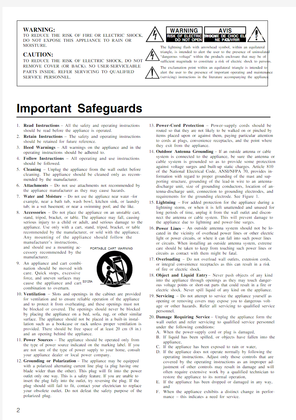
8.Accessories – Do not place the appliance on an unstable cart,
stand, tripod, bracket, or table. The appliance may fall, causing serious injury to a child or adult, and serious damage to the appliance. Use only with a cart, stand, tripod, bracket, or table recommended by the manufacturer, or sold with the appliance.
Any mounting of the appliance should follow the manufacturer’s instructions,
and should use a mounting ac-
cessory recommended by the
manufacturer.
9.An appliance and cart combi-
nation should be moved with
care. Quick stops, excessive
force, and uneven surfaces may
cause the appliance and cart
combination to overturn.
10.Ventilation – Slots and openings in the cabinet are provided
for ventilation and to ensure reliable operation of the appliance and to protect it from overheating, and these openings must not be blocked or covered. The openings should never be blocked by placing the appliance on a bed, sofa, rug, or other similar surface. The appliance should not be placed in a built-in instal-lation such as a bookcase or rack unless proper ventilation is provided. There should be free space of at least 20 cm (8 in.) and an opening behind the appliance.
11.Power Sources – The appliance should be operated only from
the type of power source indicated on the marking label. If you are not sure of the type of power supply to your home, consult your appliance dealer or local power company.
12.Grounding or Polarization – The appliance may be equipped
with a polarized alternating current line plug (a plug having one blade wider than the other). This plug will fit into the power outlet only one way. This is a safety feature. If you are unable to insert the plug fully into the outlet, try reversing the plug. If the plug should still fail to fit, contact your electrician to replace your obsolete outlet. Do not defeat the safety purpose of the polarized plug.13.Power-Cord Protection – Power-supply cords should be
routed so that they are not likely to be walked on or pinched by items placed upon or against them, paying particular attention to cords at plugs, convenience receptacles, and the point where they exit from the appliance.
14.Outdoor Antenna Grounding – If an outside antenna or cable
system is connected to the appliance, be sure the antenna or cable system is grounded so as to provide some protection against voltage surges and built-up static charges. Article 810 of the National Electrical Code, ANSI/NFPA 70, provides in-formation with regard to proper grounding of the mast and sup-porting structure, grounding of the lead-in wire to an antenna-discharge unit, size of grounding conductors, location of an-tenna-discharge unit, connection to grounding electrodes, and requirements for the grounding electrode. See Figure 1.
15.Lightning – For added protection for the appliance during a
lightning storm, or when it is left unattended and unused for long periods of time, unplug it from the wall outlet and discon-nect the antenna or cable system. This will prevent damage to the appliance due to lightning and power-line surges.
16.Power Lines – An outside antenna system should not be lo-
cated in the vicinity of overhead power lines or other electric light or power circuits, or where it can fall into such power lines or circuits. When installing an outside antenna system, extreme care should be taken to keep from touching such power lines or circuits as contact with them might be fatal.
17.Overloading – Do not overload wall outlets, extension cords,
or integral convenience receptacles as this can result in a risk of fire or electric shock.
18.Object and Liquid Entry – Never push objects of any kind
into the appliance through openings as they may touch danger-ous voltage points or short-out parts that could result in a fire or electric shock. Never spill liquid of any kind on the appliance.
19.Servicing – Do not attempt to service the appliance yourself as
opening or removing covers may expose you to dangerous volt-age or other hazards. Refer all servicing to qualified service personnel.
20.Damage Requiring Service – Unplug the appliance form the
wall outlet and refer servicing to qualified service personnel under the following conditions:
A.When the power-supply cord or plug is damaged,
B.If liquid has been spilled, or objects have fallen into the
appliance,
C.If the appliance has been exposed to rain or water,
D.If the appliance does not operate normally by following the
operating instructions. Adjust only those controls that are
covered by the operating instructions as an improper ad-
justment of other controls may result in damage and will
often require extensive work by a qualified technician to
restore the appliance to its normal operation,
E.If the appliance has been dropped or damaged in any way,
and
F.When the appliance exhibits a distinct change in perfor-
mance – this indicates a need for service.
Important Safeguards
PORTABLE CART WARNING
S3125A
2
3
1.Warranty Claim
You can find the serial number on the rear panel of this unit. In case of warranty claim, please report this number.2.Recording Copyright
Recording of copyrighted material for other than personal use is illegal without permission of the copyright holder.3.AC Fuse
The fuse is located inside the chassis and is not user-serviceable. If power does not come on, contact your Onkyo authorized service station.4.Care
From time to time you should wipe the front and rear panels and the cabinet with a soft cloth. For heavier dirt, dampen a soft cloth in a weak solution of mild detergent and water, wring it out dry, and wipe off the dirt. Following this, dry immediately with a clean cloth. Do not use rough material, thinners, alcohol or other chemi-cal solvents or cloths since these could damage the finish or remove the panel lettering.5.Power
WARNING
BEFORE PLUGGING IN THE UNIT FOR THE FIRST TIME,READ THE FOLLOWING SECTION CAREFULLY.
The voltage of the available power supply differs according to country or region. Be sure that the power supply voltage of the area where this unit will be used meets the required voltage (e.g., AC 230 V, 50 Hz or AC 120 V, 60 Hz) written on the rear panel.
Worldwide models are equipped with a voltage selector to conform to local power supplies. Be sure to set this switch to match the volt-age of the power supply in your area before plugging in the unit.For British models
Replacement and mounting of an AC plug on the power supply cord of this unit should be performed only by qualified service personnel.
IMPORTANT
The wires in the mains lead are coloured in accordance with the following code:Blue :Neutral Brown :Live
As the colours of the wires in the mains lead of this apparatus may not correspond with the coloured markings identifying the termi-nals in your plug, proceed as follows:
The wire which is coloured blue must be connected to the terminal which is marked with the letter N or coloured black.
The wire which is coloured brown must be connected to the termi-nal which is marked with the letter L or coloured red.
IMPORTANT
A 5 ampere fuse is fitted in this plug. Should the fuse need to be replaced, please ensure that the replacement fuse has a rating of 5amperes and that it is approved by ASTA or BSI to BS1362. Check for the ASTA mark or the BSI mark on the body of the fuse.
IF THE FITTED MOULDED PLUG IS UNSUITABLE FOR THE SOCKET OUTLET IN YOUR HOME THEN THE FUSE SHOULD BE REMOVED AND THE PLUG CUT OFF AND DIS-POSED OF SAFELY. THERE IS A DANGER OF SEVERE ELECTRICAL SHOCK IF THE CUT OFF PLUG IS INSERTED INTO ANY 13 AMPERE SOCKET.
If in any doubt, consult a qualified electrician.
Precautions
(NEC ART 250, PART H)
S2898A
21.Replacement Parts – When replacement parts are required, be
sure the service technician has used replacement parts specified by the manufacturer or have the same characteristics as the original part. Unauthorized substitutions may result in fire,electric shock, or other hazards.
22.Safety Check – Upon completion of any service or repairs to the
appliance, ask the service technician to perform safety checks to determine that the appliance is in proper operation condition.23.Wall or Ceiling Mounting – The appliance should be mounted
to a wall or ceiling only as recommended by the manufacturer.24.Heat – The appliance should be situated away from heat
sources such as radiators, heat registers, stoves, or other appli-ances (including amplifiers) that produce heat.
For U.S. models
Note to CATV system installer:
This reminder is provided to call the CATV system installer ’s at-tention to Section 820-40 of the NEC which provides guidelines for proper grounding and, in particular, specifies that the cable ground shall be connected to the grounding system of the building, as close to the point of cable entry as practical.FCC Information for User
CAUTION:
The user changes or modifications not expressly approved by the party responsible for compliance could void the user ’s authority to operate the equipment.NOTE:
This equipment has been tested and found to comply with the limits for a Class B digital device, pursuant to Part 15 of the FCC Rules.These limits are designed to provide reasonable protection against harmful interference in a residential installation. This equipment generates, uses and can radiate radio frequency energy and, if not installed and used in accordance with the instructions, may cause harmful interference to radio communications. However, there is no guarantee that interference will not occur in a particular installa-tion. If this equipment does cause harmful interference to radio or television reception, which can be determined by turning the equip-ment off and on, the user is encouraged to try to correct the interfer-ence by one or more of the following measures:?Reorient or relocate the receiving antenna.
?Increase the separation between the equipment and receiver.?Connect the equipment into an outlet on a circuit different from that to which the receiver is connected.
?Consult the dealer or an experienced radio/TV technician for help.
For Canadian models
NOTE:
THIS CLASS B DIGITAL APPARATUS COMPLIES WITH CA-NADIAN ICES-003.
For models having a power cord with a polarized plug:
CAUTION: TO PREVENT ELECTRIC SHOCK, MATCH
WIDE BLADE OF PLUG TO WIDE SLOT, FULLY INSERT.Modele pour les Canadien
REMARQUE:
CET APPAREIL NUM éRIQUE DE LA CLASSE B EST CON-FORME à LA NORME NMB-003 DU CANADA.Sur les mod èles dont la fiche est polaris ée:
ATTENTION: POUR éVITER LES CHOCS
éLECTRIQUES, INTRODUIRE LA LAME LA PLUS LARGE DE LA FICHE DANS LA BORNE CORRESPONDANTE DE LA PRISE ET POUSSER JUSQU ’AU FOND.
FIGURE 1:
EXAMPLE OF ANTENNA GROUNDING AS PER NATIONAL ELECTRICAL CODE, ANSI/NFPA 70
4
Supplied accessories
Check that the following accessories are supplied with the TX-DS595.
AM loop antenna × 1
FM indoor antenna × 1(connector will vary depending on model specifications)
Remote controller × 1Batteries (AA, R6 or UM-3) × 275/300
× 1
(For all models other than USA,
Canadian and European models)
Features
I 75 Watts minimum of continuous RMS power to each
of the five channels into 8 ? from 20 Hz to 20 kHz with no more than 0.08% THD (USA models, FTC rating)I 110 Watts minimum of continuous RMS power to
each of the five channels into 6 ? at 1 kHz (European models, DIN)I 140 Watts minimum to each of the five channels into
6 ? at 1kHz (Asian models, EIAJ)I Wide Range Amplifier Technology (WRAT)I Extended Frequency Response (10 Hz to 100 kHz)I Optimum Gain Volume Circuitry
I Dolby ?* Digital, DTS ?, Dolby Pro Logic II decoding I A-Form Listening Mode Memory
I Non-Scaling Configuration I Cinema Re-EQ TM
I Late night mode (high, low, off)I 5.1-Channel input
I 4 Assignable digital inputs (2 coaxial, 2 optical)I Smart Scan Navigator with LEDs I 40 FM/AM random presets I IntelliVolume
I Powerful programmed/learning remote with macros
and mode-key LEDs
*Manufactured under license from Dolby Laboratories.
“Dolby ”, “Pro Logic ” and the double-D symbol are trademarks of Dolby Laboratories. Confidential Unpublished Works. ?1992-1997 Dolby Laboratories, Inc. All rights reserved.?Re-Equalization and the “Re-EQ ” logo are trademarks of Lucasfilm Ltd.Manufactured under license of Lucasfilm Ltd.?Manufactured under license from Digital Theater Systems, Inc. US Pat.No.5,451,942 and other worldwide patents issues and pending. “DTS ”and “DTS Digital Surround ” are trademarks of Digital Theater Systems,Inc.? 1996 Digital Theater Systems, Inc. All rights reserved.
5
Installing the remote controller batteries
1.Remove the battery compartment cover by pressing
and sliding the cover.2.Insert two AA (R6 or UM-3) batteries into the battery
compartment. Carefully follow the polarity diagram (positive (+) and negative (–) symbols) inside the battery compartment.3.After batteries are installed and seated correctly,
replace the compartment cover.
Before using this unit
Setting the Voltage selector (Worldwide models only)
Worldwide models are equipped with a voltage selector to conform with local power supplies. Be sure to set this switch to match the voltage of the power supply in your area before plugging in the unit.Determine the proper voltage for your area: 220-230 V or 120 V.If the preset voltage is not correct for your area, insert a screwdriver into the groove in the switch. Slide the switch all the way to the upper (120 V) or to the lower (220-230 V), whichever is appropriate.
Notes:
?Do not mix new batteries with old batteries or different kinds of batteries.
?To avoid corrosion, remove the batteries if the remote controller is not to be used for a long time.
?Remove dead batteries immediately to avoid damage from corrosion. If the remote controller does not operate smoothly,replace both the batteries at the same time.
?The life of the batteries supplied is about six months but this will vary depending on usage.
Using the remote controller
Point the remote controller toward the remote control sensor. The STANDBY indicator lights up when the unit receives a signal from the remote controller.
Notes:
?Place the unit away from strong light such as direct sunlight or inverted fluorescent light which can prevent proper operation of the remote controller.
?Using another remote controller of the same type in the same room or using the unit near equipment which uses infrared rays may cause operational interference.
?Do not put objects on the remote controller. Its buttons may be pressed by mistake and drain the batteries.
?Make sure the audio rack doors do not have colored glass.Placing the unit behind such doors may prevent proper remote controller operation.
?If there is any obstacle between the remote controller and the
6
Front panel facilities
Here is an explanation of the controls and displays on the front panel of the TX-DS595.
Front panel
Front panel display
Speakers A/B indicators
Sleep indicator Multi function display
Listening mode or digital input format indicators
Tuning indicators
7
Front panel facilities
For operational instructions, see page indicated in brackets [ ].
Turns on and off the main power supply for the TX-DS595.Lights when the TX-DS595 is in the standby state and flashes when
a signal is received from the remote controller.
Press to turn on the TX-DS595 when in the standby state. Press again
to return the TX-DS595 to the standby state.
Press these buttons to turn on and off speakers systems A and B.
Press to select the channel whose level is to be adjusted.
The MASTER VOLUME dial is used to control the volume.To listen with headphones, plug a pair headphones with a standard stereo plug into the PHONES jack on the TX-DS595 front panel.When you connect headphones, the unit will enter STEREO mode automatically and no sound will be heard from the speakers. If you have selected MULTI CH INPUT, you will hear sound only from the FRONT L and R channels. Note that the volume level for the
headphones is adjustable.
This button is used to select the type of audio input signal. Each time pressed, the setting cycles from “AUTO ” → “MULTICH ” →“ANALOG ”
and back.
AM, PHONO, and CD) [25]
These buttons are used to select the input source.
Boosts or cuts the bass response. Bass adjustment is effective only
for the front speakers and headphones.
Boosts or cuts the treble response. Treble adjustment is effective
only for the front speakers and headphones.
[19, 20, 22, 24-27, 30-32]
Used to make settings in the setup display, change listening mode
settings, and more.
Press to enter and exit the setup mode.
Press to move up one level in the setup mode.
The DISPLAY button is used to display information about the current input source signal. Each time you press the display button,the screen changes to show you different information concerning the
input signal.
This button is only available on European models. Use this button to help tune into the Radio Data System (RDS) for FM broadcasting.RDS was developed within the European Broadcasting Union (EBU) and is available in most European countries. Each time the button is pressed, the display changes from RT (radio text) to PTY
(program type) to TP (traffic program) and then back to RT again.Press to set the brightness of the front display. There are 3 settings
available: normal, dark, and very dark.
When there is too much noise in the stereo reception of an FM
broadcast, press to turn off the FM MUTE function.
This button is used to assign the radio station that is currently tuned in to a preset channel or delete a previously preset station.
Use these buttons to change the tuner frequency. The tuner frequency is displayed in the front display and it can be changed in 50 kHz increments for FM and 10 kHz (or 9 kHz) increments for AM.
When FM is selected, you can hold down one of the tuning buttons and then release it to activate the auto-search feature. It will search for a station in the direction of the button you pressed and stop when it tunes into one.
When AM or FM is selected as the input source, press one of these buttons to jump to a radio station that you preset using the PRESET MEMORY button. Pressing the right button moves from the most recently preset station to older ones, and pressing the left button moves in the reverse order.
Remote controller
This indicator acts as a guide when commands are programmed into
or sent by the remote controller. It also warns the user when an error
is made or battery power is low.
ON: Turns on the TX-DS595.
STDBY: Places the TX-DS595 in the standby state.
Be aware that pressing the STDBY button only places the TX-
DS595 in standby and does not turn the power completely off.
Sets the sleep function.
The SLEEP button enables you to set the TX-DS595 to turn off
automatically after a specified time period.
For executing and programming the Direct Macro function.
For selecting the component to be operated by the remote controller.
When a MODE button is pressed, it will light green for 8 seconds.
The selected MODE button will also light whenever any other
operation button is pressed to tell you which mode the remote
controller is in.
Press to move up one level in the setup mode.
When in the RCVR mode, for selecting a tuner preset channel.
For selecting the disc to be played back for components with disc
changers when in the DVD or CD modes.
CH SEL: For selecting the speaker for level adjustment when in the
RCVR mode. Used together with the LEVEL / buttons.
TOP MENU: When in the DVD mode, for displaying the menu
screen(s) recorded on DVD media.
AUDIO: For selecting the audio input signal. The setting changes
from “AUTO” to “MULTICH” to “ANALOG” and back each time
this button is pressed.
TV/VCR: Must be preprogrammed for use in the TV and VCR
modes.
LEVEL /: Select the speaker whose volume is to be adjusted
using the CH SEL button and adjust the volume using the LEVEL /
buttons in the RCVR mode. [9, 27]
ANGLE: When in the DVD mode, for selecting a camera angle
when a DVD-Video is recorded with multiple angle playback. [36]
SUBTITLE: When in the DVD mode, for selecting one of the
subtitle languages recorded on a DVD-Video. [36]
For operating Onkyo components connected to the TX-DS595.
8
9
Remote controller
Selects an input source.
Same as the input selector buttons on front panel of the TX-DS595.The input source for each buttons is given here. DVD:DVD, CD:CD,V1:VIDEO1, V2:VIDEO2, V3:VIDEO3, V4:Not used with the TX-DS595, T1:TAPE, T2:Not used with the TX-DS595, TUN:FM/AM,
PH:PHONO.
Re-EQ/DISPLAY/DIMMER buttons
1 to 9, +10, --/---, 0: For entering the number of a track.
STEREO, DIRECT, DSP /, SURR, A.ST: You can select a listening mode. [25, 28]
STEREO: Changes the listening mode directly to the Stereo listening mode. If pressed, the listening mode for the selected input source set in the Listening Mode Preset is also changed to the Stereo listening mode.
SURR (Surround): Changes the listening mode to the surround mode for the current input signal (e.g., Dolby Pro Logic II,Dolby Digital, or DTS). If pressed, the listening mode for the selected input source set in the Listening Mode Preset is also changed to the Surround listening mode.
For Dolby Pro Logic II, this button also changes the mode between Dolby Pro Logic II Movie and Dolby Pro Logic II Music.
DIRECT: Changes the listening mode directly to the Direct listening mode. If pressed, the listening mode for the selected input source set in the Listening Mode Preset is also changed to the Direct listening mode.
A.ST (All Channel Stereo): Changes the listening mode directly to the Stereo listening mode. If pressed, the listening mode for the selected input source set in the Listening Mode Preset is also changed to the All Channel Stereo listening mode.DSP /: Changes the listening mode as shown below.
Direct ? Stereo ? Surround ? Orchestra ? Unplugged ?Studio-Mix ? TV Logic ? All Ch Stereo ? Direct.
If pressed, the listening mode for the selected input source set in the Listening Mode Preset is also changed.Re-EQ: Depending on the listening mode, you can turn the cinema re-equalization function on or off. [25]
Re-EQ (re-equalization) takes the edginess or “brightness ” out of your home cinema sound to compensate for the fact that sound mixed for theaters may sound too bright when played back through speakers in the home environment.
On: Select to turn on the re-equalization filter.Off: Select to turn off the re-equalization filter.Note:
The Re-EQ function is effective on the Dolby Pro Logic II Surround and Dolby Digital Surround.
SP A, SP B: For turning on and off speakers systems A and B. [26]DISPLAY:
For changing the display in the front display. [26]DIMMER: Adjusts the display brightness.
There are three settings available: normal, dark and very dark.
For executing and programming the Macro function.Press to enter and exit the setup mode.
For selecting and entering settings in the setup mode.
For adjusting the volume.
TEST: Outputs a test tone for setting speaker levels.
Use this button in conjunction with the LEVEL / and CH SEL buttons to calibrate the speakers levels.1.Press the TEST button.
A test sound (pink noise) will be heard from the left front speaker. At this point, it is not necessary to adjust the volume of the test sound.
2.Press the CH SEL button.
The test sound will now be heard from a different speaker.
https://www.360docs.net/doc/843704657.html,e the LEVEL / buttons to adjust the volume of the test sound from this speaker to the same level that you heard from the previous speaker.
4.Repeat the procedure in step 2 and 3 until the volume of the test sound from all speakers is the same level.
Each time you press the CH SEL button, the test sound will be heard from a different speaker. The speaker order for calibration is front left → center → front right → surround right → surround left → subwoofer.
5.Press the TEST button to exit the setting.
For a more detailed explanation of how to calibrate the speaker levels, see page 20.
MENU: When in the DVD mode, this button displays the DVD
menu.
Activates the mute function.
ZONE 2: Not used with the TX-DS595.
SEARCH: When in the DVD mode, for finding the specific section on a disc where you want to start playback.
ENTER: When in the MD mode, for confirming the selection.
10
Connections
Here is explanation of how to connect the main components to the TX-DS595 in the standard manner. There are many ways that any one component can be connected, and it is up to you to decide which method best fits your situation. The directions given here are only one option and should only be thought of as such. It is best to fully understand the nature of each connector and terminal as well as each of your components and their features to ascertain which method of connection is best.
?Be sure to always refer to the instructions that came with the component that you are connecting.
?Do not plug in the power cord until all connections have been made.
?For input jacks, red connectors (marked R) are used for the right channel, white connectors (marked L) are used for the left channel, and yellow connectors (marked V) are used for video connection.
?Do not bind audio/video connection cables with power cords and speaker cables. Doing so may adversely affect the picture and sound quality.
?When using the digital inputs, make sure to also connect the
analog connections whenever possible.
?Insert all plugs and connectors securely. Improper connections can result in noise, poor performance, or
damage to the equipment.
?When using one of the optical input jacks, remove the protective cap and keep it safely. When the jack is not used,replace the protective cap.
?When using an optical input jack, always use an optical fiber cable.
Optical digital input terminal
An optical digital input terminal is equipped with a protection cap. When connecting,remove this cap. When not using, put the cap back on the terminal.
Connecting your video Default setting Input source Digital input Multichannel
DVD COAX 1Yes VIDEO 1COAX 2No VIDEO 2----No VIDEO 3OPT 2No VIDEO 4----No TAPE ----No
FM AM PHONO ----No CD
OPT 1No
COAX: Coaxial OPT: Optical ----: No setting : Not applicable
Connections
Connecting your audio components
Below is an example of how you can connect your audio components to the TX-DS595. Refer to the diagram above for the following connection examples.
1.Connecting a turntable (PHONO)
Using an RCA-type audio connection cable, connect the output terminal on the turntable to the PHONO input jacks on the TX-DS595. Make sure that you properly connect the left channel to the L jack and the right channel to the R jack.
Note:
The TX-DS595 is designed for use with moving magnet cartridges. For proper operation, connect a ground (or earth) wire to the GND terminal. For some turntables, however, connecting the ground wire may cause increased noise, and in such a case, a ground wire is not necessary and should not be connected.
2.Connecting a compact disc player (CD)
Using an RCA-type audio connection cable, connect the output terminal on the compact disc player to the CD input jacks on the TX-DS595. Make sure that you properly connect the left channel to the L jack and the right channel to the R jack.
If the compact disc player has a digital output jack as well, be sure to also connect it to either a DIGITAL INPUT (COAXIAL) or DIGITAL INPUT (OPTICAL) jack on the TX-DS595 depending on the type of connector on the compact disc player.With the initial settings of the TX-DS595, the CD input source is set for digital input at the OPTICAL 1 jack.
If the digital connection is made at a different jack, this must be changed at the setup menu: Input Setup → Audio Setup → Digital Input (see page 29).
3.Connecting a cassette tape deck, MD recorder, DAT
deck, or CD recorder (TAPE)
Using an RCA-type audio connection cable, connect the output terminals (PLAY) of the device to the TAPE IN jacks on the TX-DS595 and the input terminals (REC) to the TAPE OUT jacks. Make sure that you properly connect the left channel to the L jack and the right channel to the R jack.
If the device has a digital output jack as well, be sure to also connect it to either a DIGITAL INPUT (COAXIAL) or DIGITAL INPUT (OPTICAL) jack on the TX-DS595 depending on the type of connector on the device.
With the initial settings of the TX-DS595, the TAPE input source is set for no digital input.
If you connect the device to the DIGITAL INPUT terminal, then this input source must be set for digital input at the setup menu: Input Setup → Audio Setup → Digital Input (see page 29).
Audio connection cable
: Signal flow
Left (White)L
11
12
Connecting your video components
Below is an example of how you can connect your video components to the TX-DS595. Refer to the diagram above for the following connection examples.
The flow of the video signals is as follows:
?The signal that comes in from VIDEO IN is sent to VIDEO OUT.
?The signal that comes in from S VIDEO IN is sent to S VIDEO OUT 4.Connecting a DVD player (DVD)
If the device is equipped with an S video output terminal, connect it to the DVD S VIDEO IN terminal with an S video cable. If it does not have an S video output terminal, connect its video output terminal to the DVD VIDEO IN terminal using an RCA-type video connection cable. You do not need to connect to both the DVD S VIDEO IN and DVD VIDEO IN terminals.
Using an RCA-type audio connection cable, connect the audio output terminal on the device to the audio DVD IN jacks on the TX-DS595. Make sure that you properly connect the left channel to the L jack and the right channel to the R jack.
If the device has a digital output jack as well, be sure to also connect it to either a DIGITAL INPUT (COAXIAL) or DIGITAL INPUT
(OPTICAL) jack on the TX-DS595 depending on the type of connector on the DVD player.
With the initial settings of the TX-DS595, the DVD input source is set for digital input at the COAXIAL 1 jack.
If the digital connection is made at a different jack, this must be changed at the setup menu: Input Setup → Audio Setup → Digital Input (see page 29).
5.Connecting a video cassette recorder (VIDEO 1)
If the video cassette recorder is equipped with an S video output terminal, connect it to the S VIDEO 1 IN terminal with an S video cable. If it does not have an S video output terminal, connect its video output terminal to the VIDEO 1 IN terminal using an RCA-type video connection cable. You do not need to connect to both the S VIDEO 1 IN and VIDEO 1 IN terminals.
Using an RCA-type audio connection cable, connect the audio output terminal on the video cassette recorder to the same VIDEO 1IN audio jacks on the TX-DS595 and audio input terminal to the VIDEO 1 OUT audio jacks. Make sure that you properly connect the
left channel to the L jack and the right channel to the R jack.
Audio connection cable L
R
Video connection cable
S Video connection cable
Left (White)
Right (Red)
13
If the device has a digital output jack as well, be sure to also connect it to either a DIGITAL INPUT (COAXIAL) or DIGITAL INPUT (OPTICAL) jack on the TX-DS595 depending on the type of connector on the device.
With the initial settings of the TX-DS595, the VIDEO 1 input source is set for digital input at the COAXIAL 2 jack.
If the digital connection is made at a different jack, this must be changed at the setup menu: Input Setup → Audio Setup → Digital Input (see page 29).
6.Connecting a satellite tuner, television, or settop box
(VIDEO 2/3)
If the device is equipped with an S video output terminal, connect it to the S VIDEO 3 IN terminal with an S video cable. If it does not have an S video output terminal, connect its video output terminal to the VIDEO 3 IN terminal using an RCA-type video connection cable. You do not need to connect to both the S VIDEO 3 IN and VIDEO 3 IN terminals.
Using an RCA-type audio connection cable, connect the audio output terminal on the satellite tuner or television to the same VIDEO 3 IN audio jack on the TX-DS595. Make sure that you properly connect the left channel to the L jack and the right channel to the R jack.
If the device have a digital output jack as well, be sure to also connect it to either a DIGITAL INPUT (COAXIAL) or DIGITAL INPUT (OPTICAL) jack on the TX-DS595 depending on the type of connector on the device.
With the initial settings of the TX-DS595, the VIDEO 3 input source is set for digital input at the OPTICAL 2 jack.
If the digital connection is made at a jack different from the initial settings, this must be changed at the setup menu: Input Setup →Audio Setup → Digital Input (see page 29).
You can also connect the device to the VIDEO 2 IN input jacks on the TX-DS595 just like you can to the VIDEO 3 IN input jacks.With the initial settings of the TX-DS595, the VIDEO 2 input source is set for no digital input.
If you connect the device to the DIGITAL Input terminal, then this input source must be set for digital input at the setup menu: Input Setup → Audio Setup → Digital Input (see page 29).
7.Connecting a television monitor or projector
(MONITOR OUT)
If the monitor or projector is equipped with an S video output terminal, connect it to the MONITOR OUT S VIDEO terminal with an S video cable. If it does not have an S video output terminal,connect its video output terminal to the MONITOR OUT VIDEO terminal using an RCA-type video connection cable. You do not need to connect to both the MONITOR OUT S VIDEO and MONITOR OUT VIDEO terminals.
Connections
Connect to devices with z terminals
The z terminal on the TX-DS595 is for connecting other Onkyo components equipped with the same z terminal. When a component are z -connected, you can point the remote controller supplied with the TX-DS595 at the sensor on the TX-DS595 and operate that component without having to switch remote controllers.In addition, by connecting components to the z terminal, you can also perform the system operations given below.
Power on/ready function
When the TX-DS595 is in the standby state, if an z -connected component is turned on, then the TX-DS595 also turns on and the input source selected at the TX-DS595 automatically switches to that component.
If the power cord for an z -connected component is connected to the AC OUTLET on the TX-DS595, or if the TX-DS595 is turned on, this function will not work.
Direct change function
When the play button is pressed at an z -connected component, the input source selected at the TX-DS595 automatically changes to that component.
Power off function
When the TX-DS595 is placed in the standby state, all z -connected components are also automatically put into the standby state.
CAUTION
If an MD recorder is connected to the TAPE jack on the TX-DS595,switch the Input Selector from TAPE to MD (see page 16).
To connect components using the z terminal, simply connect a remote control cable from this z terminal to the z terminal of the other component. An z remote control cable with a 1/8-inch (3.5-mm) miniature two-conductor plug comes with every cassette tape deck, compact disc player, MD recorder, and DVD player that has an z terminal.
?For remote control operation, the audio connection cables must also be connected.
?The RC-447M remote controller does not support turntables.?If a component has two z terminals, you can use either one to connect to the TX-DS595. The other one can be used to daisy chain with another component.
?With Onkyo DVD players, you can enter the pre-program code so that you can operate the DVD player directly with the remote controller without connecting the z terminals (see page 38).
14
Connecting speakers
Positioning speakers
Speaker placement plays an important role in the reproduction of Surround sound. The placement of the speakers varies depending on the size of the room and the wall coverings used in the room. The illustration shows an example of a layout for standard speaker placement. Refer to this example when you position the speakers in order to experience the best of Surround sound.
Standard speaker placement
For ideal Surround effects, all speakers should be installed. If a center speaker or subwoofer is not connected, the sound from the unused channel is properly distributed to the connected speakers in order to produce the best Surround sound possible.
Front: The left, right, and center speakers should face the seated listener and be placed at ear level. The center speaker produces a richer sound image by enhancing the perception of the sound ’s source and movement.
Surround: Place the left and right Surround speakers 3 feet (1meter) above the listener ’s ear level and facing toward the sides of the room, making sure that the listener is within the speakers ’ dis-persion angle. These speakers produce the feel of a moving sound while creating the sensation of being in the middle of the action.Subwoofer: Install a subwoofer with a built-in power amplifier for powerful bass sounds. The placement of the subwoofer does not affect the final quality of the sound image too much, so you can install it with the room layout in mind.
Refer to the speaker ’s instruction manual for more details.
15
Use the PRE OUT SUBWOOFER jack to connect a subwoofer with
a built-in power amplifier. If your subwoofer does not have a built-in amplifier, connect an amplifier to the PRE OUT SUBWOOFER jack and the subwoofer to the amplifier.
Connecting speakers
Center speaker Front left speaker A
Front right speaker A Surround left speaker
Surround right speaker Subwoofer
Front left speaker B
Front right speaker B NO!
Connecting speakers
1.Check the impedance of the speakers you are
connecting.
The TX-DS595 requires speakers with an impedance of 4 ? or greater. Connecting speakers with an impedance of less than 4 ?may damage the TX-DS595.2.Set the IMPEDANCE SELECTOR switch according to
the impedance of the speakers being connected.
If all speakers have an impedance of 6 ? or greater, slide the IMPEDANCE SELECTOR switch to the left (6 OHMS MIN./SPEAKER). If one or more speakers have an impedance of less than 6 ?, slide the IMPEDANCE SELECTOR switch to the right (4 OHMS MIN./SPEAKER).
?When you are using only one speaker or when you wish to listen to monaural (mono)sound, a single speaker should never be connected in parallel to both the right and left-channel terminals simultaneously.?To prevent damage to circuitry,never short-circuit the positive (+) and negative (–) speaker wire.
Notes:
?The power to the TX-DS595 must not be turned on when changing the IMPEDANCE SELECTOR setting.4 ? or above/speaker 6 ? or above/speaker
R L R L
?Be sure to connect the positive and negative cables for the speakers properly. If they are mixed up, the left and right signals will be reversed and the audio will sound unnatural.
?Do not connect more than one speaker cable to one speaker terminal. Doing so may damage the TX-DS595.
?Use FRONT SPEAKERS B terminals to connect a second pair of front speakers.
?When you listen to surround audio or select Multichannel, be sure to turn on SPEAKERS A.
ON
RCVR MODE
STDBY Connecting the power
Turning the power on from the remote controller:
Before you can use the remote controller, you must perform steps 1
and 2 above and place the TX-DS595 in the standby state.
TX-DS595 (take it out of the standby
state).
To return the TX-DS595 to the standby
state, press the STDBY button.
?The TX-DS595 is shipped with the main power (POWER)
switch in the on position (ON). When the power cord is
plugged in for the first time, the TX-DS595 will automatically
enter the standby state and the STANDBY indicator will light
(same condition after step 2 below).
?Before you plug in the TX-DS595, confirm that all connections
have been made properly.
?Turning on the power may cause a momentary power surge,
which might interfere with other electrical equipment on the
same circuit, such as computers. If this happens, use a wall outlet
on a different circuit.
1.Plug the power cord into an AC wall outlet.
2.Press the POWER switch to set the
TX-DS595 to standby state.
The STANDBY indicator will light up.
3.Press the STANDBY/ON button to
turn on the TX-DS595. The display
and four jog dial indicators will light
up and the STANDBY indicator will
turn off.
If you press the STANDBY/ON button
again, the receiver returns to Standby mode.
SEND/LEARN
indicator
STANDBY/ON
To change the display of the input source from TAPE to
MD:
If you connected an MD recorder to the TAPE jack on the TX-
DS595, you can have “MD” appear when the TAPE source button is
pressed. By changing the display, if an Onkyo MD recorder z-
connected, the z system functions will become enabled.
Changing the display:
Press and hold down the TAPE source button until the display
changes from TAPE to MD (approx. 3 seconds).
To return the display to its original setting, perform the same
procedure. This setting is necessary to allow z system functions
for the connected cassette tape or MD recorder.
Memory preservation
This unit does not require memory preservation batteries. A built-
in memory power backup system preserves the contents of the
memory during power failures and even when the POWER
switch is set to off. The POWER switch must be set to on in order
to charge the backup system.
The memory preservation period after the unit has been turned off
varies depending on climate and placement of the unit. On the
average, memory contents are protected over a period of a few
weeks after the last time the unit has been turned off. This period
is shorter when the unit is exposed to a highly humid climate.
16
Connecting antennas
17
Connecting antennas
1.With your fingernail, or a small screwdriver, press the
stoppers of the 75/300 ? antenna adapter outward
and remove the cover.
2.
If anything other than “1. SPEAKER SETUP”appears, turn the jog dial or press the and cursor buttons on the remote controller until “1. SPEAKER SETUP” appears.
Speaker Configuration
These settings tell the TX-DS595 which speakers you have connected and what size they are.
1.Press the SETUP button.
Speaker setup
3.Press the jog dial or ENTER button on
the remote controller.
YES: Select when a subwoofer is connected.
NO: Select when a subwoofer is not connected.
*If the indicators directly to the left and right of the jog dial are lit,
turning the jog dial changes the setting of the currently selected
parameter and pushing the jog dial displays the next parameter.
The display changes as follows: “1. SPEAKER SETUP”→“2.
INPUT SETUP”→“3. PREFERENCE.”
*If the indicators directly above and below the jog dial are lit,
turning the jog dial selects a group of settings and pushing the jog
dial enters the selected group (i.e. takes you one level down).
RETURN
Then turn the jog dial or press the or cursor
button on the remote controller to set the size of
your front speakers.
LARGE: Select if the front speakers are large sized.
SMALL: Select if the front speakers are small sized.
?If “NO” is selected for the Subwoofer setting, then this setting is
fixed to “LARGE”.
6.Press either the jog dial or the
cursor button on the remote controller
once.
Then turn the jog dial or press the or cursor
buttons on the remote controller to set whether
or not a center speaker is connected and, if one
is connected, its size.
NONE: Select if no center speaker is connected.
LARGE: Select if the center speaker is large sized.
SMALL: Select if the center speaker is small sized.
?If “SMALL” is selected for the Front setting, then “LARGE”
cannot be selected for this setting.
7.Press either the jog dial or the
cursor button on the remote controller
once.
Then turn the jog dial or press the or cursor
button on the remote controller to set whether
or not surround speakers are connected and, if
they are connected, their size.
NONE: Select if no surround left and right speakers are connected.
LARGE: Select if the surround left and right speakers are large
sized.
SMALL: Select if the surround left and right speakers are small
sized.
?If “SMALL” is selected for the Front setting, then “LARGE”
cannot be selected for this setting.
Pressing the jog dial again or cursor button returns you to the
subwoofer setting.
8.Press the RETURN button.
You return to the “SPEAKER CONFIG?”
display.
Notes:
?If you press the RETURN button again, you go back up one more
level.
?To exit the setup mode immediately, press the SETUP button. Follow the steps below before you start operating the unit.
TX-DS595Remote
controller
19
20
Speaker setup
The test sound will now be heard from a different speaker.
5.Turn the jog dial or press the or
cursor buttons on the remote
controller to adjust the volume of the test sound from this speaker to the same level that you heard from the previous speaker.
You can adjust the level in the range between -12 dB and +12 dB.6.Repeat the procedure in step 4 and 5 until the volume of
the test sound from all speakers is the same level.
Each time you press the jog dial or the button on the remote controller, the test sound will be heard from a different speaker. The speaker order for calibration is LEFT (front left) → CENTER (center) → RIGHT (front right) → SURR RIGHT (surround right)→ SURR LEFT (surround left) → SUBWOOFER (subwoofer).7.Press the RETURN button.
You return to the “LEVEL CAL?” display.Notes :
?If you press the RETURN button again, you go back up one more
level.?To exit the setup mode immediately, press the SETUP button.You can also press the TEST button on the remote controller to perform the Level Calibration setting. For more details, see page 9.
3.Press the jog dial or ENTER button on
the remote controller.
A test sound (pink noise) will be heard from the left front speaker. At this point, it is not necessary to adjust the volume of the test sound.
2.Press the jog dial or the ENTER button
on the remote controller.
FEET: Select if you will enter the distances in feet.
METERS: Select if you will enter the distances in meters.4.Press the jog dial or the cursor
button on the remote controller.
3.Press the jog dial or the ENTER button
on the remote controller.
2.
Press the jog dial or the ENTER button
on the remote controller.
Speaker Distance
These settings tell the TX-DS595 how far away your speakers are located from the listening position so that it can provide the optimum sound space. If you are continuing from setting the speaker configuration and are still in the setup mode, skip directly to step 2.
1.Press the SETUP button.
If anything other than “1. SPEAKER SETUP ”appears, turn the jog dial or press the and cursor buttons on the remote controller until “1.SPEAKER SETUP ” appears.
Level Calibration
These settings allow you to set the volume levels of each speaker individually so that they all sound at the same level when heard from the listening position. If you are continuing from setting the speaker distances and are still in the setup mode, skip directly to step 2.
1.Press the SETUP button.
If anything other than “1. SPEAKER SETUP ”appears, turn the jog dial or press the and cursor buttons on the remote controller until “1.SPEAKER SETUP ” appears.
Then turn the jog dial or press the and cursor buttons on the remote controller to set the distance from the front speakers to the listening position.
Then turn the jog dial or press the cursor button on the remote controller to display “SPEAKER DISTANCE.”
Then turn the jog dial or press the and cursor buttons on the remote controller to select the unit of measurement.
You can set the distance in the range of 1 feet (0.3 m) - 30 feet (9 m)in 1 feet (0.3 m) steps.
5.Repeat the procedure in step 4 to set the distance from
the center speaker (CENTER) and the surround speakers (SURR L/R) to the listening position.6.Press the RETURN button.
You return to the “SP DISTANCE?” display.Notes:
?If you press the RETURN button again, you go back up one more level.?To exit the setup mode immediately, press the SETUP button.
Then turn the jog dial or press the cursor button on the remote controller to display the “LEVEL CAL.”
功放说明书
说明书 一、面板布置: 1、本功放由功放、播放器、电平指示器、扬声器四个模块组成。其中功放有放大音频信 号的功能,可把播放器音频、外接音频、话筒音频信号放大,通过调节旋钮可改变信号的大 小。播放器有读取内存卡里的音频文件并转化成音频信号(另有收音机功能)的功能。电平 指示模块是通过计算音频信号,获取音频里音调的高低信号,再通过led灯显示出来,具有 装饰的功能。扬声器是把音频信号转化成声音信号的作用。 2、正前方: 电平指示 13 14 ⑥⑦⑧⑨⑩ 11 12 ①②③④⑤ 左声道右声道①电源指示灯、②音频输入、③音量旋钮、④话筒音量旋钮、⑤话筒输 入、⑥播放器电源开关、⑦上一曲/音量-、⑧播放/暂停、⑨下一曲/音量+、⑩播放模式、11 数据线插孔、12 usb插孔、13播放器显示屏、14 sd卡插孔(注:11、12、14插孔都是输入 插孔,不能输出) 3、正后方: 变压器变压器线散热器遥控器电源线 耳机插孔 扬声器插头 注意:1、使用前检查电源线和变压器线是否完好,外层绝缘皮是否有破损, 若有破损则需要用电胶布粘住,防止皮肤接触而触电。 2、通电时最好不要触碰变压器和变压线。 3、使用时禁止触碰散热器、变压器,防止因温度过高而烫伤。 4、当使用耳机听音频时,只需把耳机插入耳机插孔,但要注意,在 使用耳机之前要控制好音量,防止音量过大而损坏耳机。一般操 作是先把音量调为最小,插入耳机后再慢慢增大。 二、使用步骤: 1、打开电源: 在打开电源前先把音乐音量,话筒音量④调为最小,并确定自带播放器开关⑥处于关闭 状态。然后把电源线接电,则电源指示灯会亮①。 2、接音频: 音频有两种,一种是外接音频输入②,另外一种是自带播放器输入,其优先级是外接音 频输入高于自带播放器音频输入。 (1)外接音频输入需用一根3.5mm音频线与外界播放器连接,另外一端必须接到功 放的外接“音频输入”②插孔,注意播放器的音量③应适当,否则将会烧坏功 放芯片和损坏喇叭。 (2)自带播放器输入:首先把优盘或sd卡插入相应位置11、12、13,然后把播放器 开关打开⑥,启动自带播放器。利用红外线遥控或播放器上的按钮进行操作。 3、调节音量: 找到音量旋钮(处正前方左端第一个旋钮③),顺时针方向旋转即为音量增大。 4、话筒的使用: 话筒选用3.5mm插头的驻极体话筒,一般连电脑话筒都可以使用,不可使用其他话筒。 话筒插头必须插到“话筒输入”⑤,注意区分“音频输入”②插孔。话筒音量也是瞬时针
A-100功放操作使用说明书
A-100 多功能立体声音频功率放大器 操作使用说明书
欢迎选购中大音响的 A-100高保真音频放大器。经过我们的精心设计,本品能产生无与伦比的超值享受,同时还能高保真的再现您所喜爱的音乐。为了确保您能熟悉本品提供的功能,我们建议您在安装和使用前,请仔细阅读本说明书的内容。 产品介绍: 这个功放的大致架构就是专为了整合PC-HIFI而设计,近年来随着电脑和互联网的普及,丰富的网络资源,免费的网络音乐共享,让我们的生活越来越离不开电脑了,然而,普通的电脑硬件加上普通的有源电脑音响也就不能满足人们对高品质音乐的需求了。PC HIFI也就应运而生了。 何谓PC HIFI?实际上就是撇开电脑本身的集成声卡,利用数字信号传输音源到外置声卡或者
解码器作为高品质音源,再由专门的功放驱动音箱,这样声音效果相比普通电脑的有源音响就有了质的提升。中大音响的A-100就是在这样的大环境下立项的,这个项目的解码部分将采用最经典的数字芯片加上专门为之独特设计的外围及后续电路,把来自电脑USB的音源转换成高品质高保真音频模拟信号,传送给功率放大电路进行足功率放大后驱动音箱,还原高素质音乐。 功放电路将采用中大独自开发的经典电路,每声道一对大功率IRFP240/9240做为后级放大,这个管子非常好声,素有甜美、厚声之美誉,曾经被PASS先生在他的很多机型上应用,也被无数PASS迷所采用。本功放的设计最大功率80瓦,峰值功率达100瓦,驱动一般的书架音箱组建高素质的PC HIFI非常合适。 中大音响在设计上从来都是不惜成本的,就连一个旋钮都是特殊定做的铝合金喷砂旋钮,非常发烧高档,A-100高保真放大器采用中大音响自主设计并开模冲压的纯铝合金拉丝氧化机箱,非市面那些型材拼凑,底板厚度达到4mm,功率管直接安装在底板上进行散热,热稳定性非常高,这样的设计可以保证整机功放管始终工作在一个非常一致的温度范围上,为充分发挥管子的特性奠定了基础。变压器是功放的动力之源,他的好坏直接关系到声音的好坏,A-100搭载了国际知名音频变压器制造商伊戈尔特殊定制的环形音频专用牛,并不惜成本加装钢带屏蔽,杜绝丁点漏磁对信噪比的影响。 专用软件仿真设计和多次实际打板调试,完全对称的发烧级PCB布线,紧凑考究的器件摆位将各种串扰降低到最低,更是采用高精度五色环金属膜电阻确保各级工作点的稳定,高达13600uF 的大水塘电容确保大动态下仍然稳若泰山,严格配对安装的晶体管确保信号的丝毫不差,发烧级音频专用电容完美校声,全能保护电路采用GOODSKY音频专用继电器确保输出无瓶颈,具有过载、过压、过流、输出短路、直流输出等保护,特殊定做的音频专用12mm电位器耐用又好声,高质量镀银机内信号线做无损信号传输,无氧铜输出线和高级纯铜镀金输出端子确保功率信号畅通无阻,很显然高质量的元器件确保了线路性能的优良发挥,想不好声音都难! A-100高保真放大器分为标准版和USB版,标准版和USB版所有配置完全一样,只是标准版不配置USB解码版,标准版适合已有外置高品质声卡、解码器或者使用CD机做音源的用户;USB版适合只有一台电脑的用户组建PC_HIFI系统。 A-100高保真功放整体声音表现平衡且富有一种贵气,非常全面的一种声音,中高频解析力高,低频干净有力,量感十足,久听不吵,非常适合近场监听,绝非那些炒作的天花乱坠的数字功放所能比拟。特别搭配以中大自主研发生产的音箱,更是如鱼得水,无论是听人声还是乐器,无论是听舒缓还是劲爆,无论是听古典还是流行,都能给你还原的淋漓尽致。 本说明书中使用的图片为示意图,旨为说明用途,可能和实物有差异,产品以实物为准。 序言及目录。。。。。。。。。。。。。。。。。。。。。。。。。。。。。。。。。。。。。。。。。。。。。。。。。。。。。。。。。。。。。。2-3 附件、使用前须知、注意事项、部件名称与功能。。。。。。。。。。。。。。。。。。。。。。。。。。。。。。4-5 扬声器的连接方法。。。。。。。。。。。。。。。。。。。。。。。。。。。。。。。。。。。。。。。。。。。。。。。。。。。。。。。。。5 音源的连接方法。。。。。。。。。。。。。。。。。。。。。。。。。。。。。。。。。。。。。。。。。。。。。。。。。。。。。。。。。。。6 操作方法。。。。。。。。。。。。。。。。。。。。。。。。。。。。。。。。。。。。。。。。。。。。。。。。。。。。。。。。。。。。。。。。。7 常见故障排除。。。。。。。。。。。。。。。。。。。。。。。。。。。。。。。。。。。。。。。。。。。。。。。。。。。。。。。。。。。。。7 规格及技术参数。。。。。。。。。。。。。。。。。。。。。。。。。。。。。。。。。。。。。。。。。。。。。。。。。。。。。。。。。。。7 保修卡。。。。。。。。。。。。。。。。。。。。。。。。。。。。。。。。。。。。。。。。。。。。。。。。。。。。。。。。。。。。。。。。。。。8
DHT11温湿度传感器与单片机之间的通信
DHT11温湿度传感器与单片机之间的通信 一DHT11的简介: 1 接口说明 建议连接线长度短于20米时用5K上拉电阻,大于20米时根据实际情况使 用合适的上拉电阻 2数据帧的描述 DATA 用于微处理器与DHT11之间的通讯和同步,采用单总线数据格式,一次通讯时间4ms左右,数据分小数部分和整数部分,具体格式在下面说明,当前小数部分用于以后扩展,现读出为零.操作流程如下: 一次完整的数据传输为40bit,高位先出。 数据格式:8bit湿度整数数据+8bit湿度小数数据 +8bi温度整数数据+8bit温度小数数据 +8bit校验和 数据传送正确时校验和数据等于“8bit湿度整数数据+8bit湿度小数数据+8bi 温度整数数据+8bit温度小数数据”所得结果的末8位。 3时序描述 用户MCU发送一次开始信号后,DHT11从低功耗模式转换到高速模式,等待主机开始信号结束后,DHT11发送响应信号,送出40bit的数据,并触发一次信号采集,用户可选择读取部分数据.从模式下,DHT11接收到开始信号触发一次温湿度采集,如果没有接收到主机发送开始信号,DHT11不会主动进行温湿度采集.采集数据后转换到低速模式。 1.通讯过程如图1所示
图1 总线空闲状态为高电平,主机把总线拉低等待DHT11响应,主机把总线拉低必须大于18毫秒,保证DHT11能检测到起始信号。DHT11接收到主机的开始信号后,等待主机开始信号结束,然后发送80us低电平响应信号.主机发送开始信号结束后,延时等待20-40us后, 读取DHT11的响应信号,主机发送开始信号后,可以切换到输入模式,或者输出高电平均可, 总线由上拉电阻拉高。 图2 总线为低电平,说明DHT11发送响应信号,DHT11发送响应信号后,再把总线拉高80us,准备发送数据,每一bit数据都以50us低电平时隙开始,高电平的长短定了数据位是0还是1.格式见下面图示.如果读取响应信号为高电平,则DHT11没有响应,请检查线路是否连接正常.当最后一bit数据传送完毕后,DHT11拉低总线50us,随后总线由上拉电阻拉高进入空闲状态。 数字0信号表示方法如图4所示
狮龙功放说明书
篇一:狮龙8105功放说明书 contents-----目录 introduction-----介绍 ? read this before operating your unit | 1-----操作前请阅读 ? safety instruction | 2-----安全教育 system connections | 4-----系统连接 front panel controls | 11-----前板控制键 universal remote controls | 13-----通用摇控器 ? remote control operation range | 15-----摇控器控制范围 ? loading batteries | 15-----安装电池 ? using functions of remote control | 16-----控制器按键功能使用 speaker setup | 19-----扬声器设置 ? setting the speaker setup manually | 20-----扬声器手动设置 ? setting the speaker setup automatically (auto speaker setup) | 22------扬声器自动设置operations-----操作 ? listening to a program source | 25-----音乐信号源欣赏(听音) ? surround sound | 28-----环绕声 ? enjoying surround sound | 30-----享受环绕效果 ? listening to radio broadcasts | 35-----收听广播电台 ? recording | 37-----录音 ? digital audio recording with minidisc recorder | 38-----用md录音机进行数字录音 ? other functions | 39-----其它功能 using the osd (on screen display)-----屏幕显示器
DHT11温湿度传感器
基于单片机的DHT11温湿度 传感器设计 姓名:史延林 指导老师:黄智伟 学院:电气工程学院 学号:20094470321 摘要: 温湿度是生活生产中的重要的参数。本设计为基于单片机的温湿度检测与控制系统,采用模块化、层次化设计。用新型的智能温湿度传感器DHT11主要实现对温度、湿度的检测,将温度湿度信号通过传感器进行信号的采集并转换成数字信号,再运用单片机STC89C52进行数据的分析和处理,为显示和报警电路提供信号,实现对温
湿度的控制报警。报警系统根据设定报警的上下限值实现报警功能,显示部分采用LCD1602液晶显示所测温湿度值。系统电路简单、集成度高、工作稳定、调试方便、检测精度高,具有一定的实用价值。 关键词:单片机;DHT11温湿度传感器; LCD1602显示 第一章:课程构思 1.1课题背景 温湿度的检测与控制是工业生产过程中比较典型的应用之一,随着传感器在生产和生活中的更加广泛的应用。在生产中,温湿度的高低对产品的质量影响很大。由于温湿度的检测控制不当,可能使我们导致无法估计的经济损失。为保证日常工作的顺利进行,首要问题是加强生产车间内温度与湿度的监测工作,但传统的方法过于粗糙,通过人工进行检测,对不符合温度和湿度要求的库房进行通风、去湿和降温等工作。这种人工测试方法费时费力、效率低,且测试的温度及湿度误差大,随机性大。目前,在低温条件下(通常指100℃以下),温湿度的测量已经相对成熟。利用新型单总线式数字温度传感器实现对温度的测试与控制得到更快的开发。但人们对它的要求越来越高,要为现代人工作、科研、学习、生活提供更好的更方便的设施就需要从数字单片机技术入手,一切向着数字化,智能化控制方向发展。 对于国内外对温湿度检测的研究,从复杂模拟量检测到现在的数字智能化检测越发的成熟,随着科技的进步,现在的对于温湿度研究,检测系统向着智能化、小型化、低功耗的方向发展。在发展过程中,以单片机为核心的温湿度控制系统发展为体积小、操作简单、量程宽、性能稳定、测量精度高,等诸多优点在生产生活的各个方面实现着至关重要的作用。 温湿度传感器除电阻式、电容式湿敏元件之外,还有电解质离子型湿敏元件、重量型湿敏元件(利用感湿膜重量的变化来改变振荡频率)、光强型湿敏元件、声表面波湿敏元件等。湿敏元件的线性度及抗污染性差,在检测环境湿度时,湿敏元件要长期暴露在待测环境中,很容易被污染而影响其测量精度及长期稳定性。1.2主要内容
DHT11中文说明书
数字温湿度传感器 DHT11 ?相对湿度和温度测量 ?全部校准,数字输出 ?卓越的长期稳定性 ?无需额外部件 ?超长的信号传输距离 ?超低能耗 ?4 引脚安装 ?完全互换 DHT11产品概述 DHT11数字温湿度传感器是一款含有已校准数字信号输出的温湿度复合 传感器。它应用专用的数字模块采集技术和温湿度传感技术,确保产品具有极 高的可靠性与卓越的长期稳定性。传感器包括一个电阻式感湿元件和一个NTC 测温元件,并与一个高性能8位单片机相连接。因此该产品具有品质卓越、超 快响应、抗干扰能力强、性价比极高等优点。每个DHT11传感器都在极为精确 的湿度校验室中进行校准。校准系数以程序的形式储存在OTP内存中,传感器 内部在检测信号的处理过程中要调用这些校准系数。单线制串行接口,使系统 集成变得简易快捷。超小的体积、极低的功耗,信号传输距离可达20米以上, 使其成为各类应用甚至最为苛刻的应用场合的最佳选则。产品为 4 针单排引 脚封装。连接方便,特殊封装形式可根据用户需求而提供。 应用领域 ?暖通空调?测试及检测设备 ?汽车?数据记录器 ?消费品?自动控制 ?气象站?家电 ?湿度调节器?医疗 ?除湿器 订货信息 型号测量范围测湿精度测温精度分辨力封装DHT11 20-90%RH 0-50℃±5%RH ±2℃ 1 4针单排直插
1、传感器性能说明 参数条件Min Typ Max 单位 湿度 分辨率 1 1 1 %RH 16 Bit 重复性±1 %RH 精度25℃±4 %RH 0-50℃±5 %RH 互换性可完全互换 量程范围0℃30 90 %RH 25℃20 90 %RH 50℃20 80 %RH 响应时间1/e(63%)25℃, 6 10 15 S 1m/s 空气 迟滞±1 %RH 长期稳定性典型值±1 %RH/yr 温度 分辨率 1 1 1 ℃ 16 16 16 Bit 重复性±1 ℃ 精度±1 ±2 ℃ 量程范围0 50 ℃ 响应时间1/e(63%) 6 30 S 2、接口说明 建议连接线长度短于20米时用5K上拉电阻,大于20米时根据实际情况使 用合适的上拉电阻 3、电源引脚 DHT11的供电电压为3-5.5V。传感器上电后,要等待1s 以越过不稳定状态在此期间无需发送任何指令。电源引脚(VDD,GND)之间可增加一个100nF 的电容,用以去耦滤波。
天乐功放说明书
天乐功放说明书 篇一:功放使用说明书 功 放 使 用 说 明 书 该说明书为东莞市奇声电子实业有限公司版权所有目录 一.面板按键功能说明---------------------------------- 1 二.功能特性------------------------------------------3 三.设置--------------------------------------------- 2 四.播放----------------------------------------------3 五.连接----------------------------------------------3 六. 配置
----------------------------------------------4 七. 附录----------------------------------------------5 八.使用注意事项---------------------------------------5 篇二:功放的说明书 说明书 一、面板布置: 1、本功放由功放、播放器、电平指示器、扬声器四个模块组成。其中功放有放大音频信 号的功能,可把播放器音频、外接音频、话筒音频信号放大,通过调节旋钮可改变信号的大 小。播放器有读取内存卡里的音频文件并转化成音频信号(另有收音机功能)的功能。电平 指示模块是通过计算音频信号,获取音频里音调的高低信号,再通过led灯显示出来,具有 装饰的功能。扬声器是把音频信号转化成声音信号的作用。 2、正前方: 电平指示 13 14 ⑥⑦⑧⑨⑩11 12①②③④⑤左声道右声
STK500功放机的使用说明书
STK-500 AV/ HI-FI audio amplifir STK-500 AV/高保真音频功率放大器 Operating Manual 使 用 说 明 书 (2010.10. REV.B ) Thank you for useing the STK-500 AV/ HI-FI audio amp the AMP in order to get the most out of all the features and bea valuable tool in helping you to understand all the AMP’s 感谢阁下使用STK-500 AV/高保真兼容功放机。在使用本功放机前,请阅读说明书,以便让您获取本机更多的特征及功能。根据说明书的可靠性,它就像工具一样,可帮助您了解本机所有的性能。 To ensure the best performance from your HI-FI amplifir, please read the Operating Manual before using the amplifir. 为保证您的高保真功放机能发挥最佳的表现,在使用本机前,请务必认真阅读本操作说明书。
目录 目 录 (1) 概 述 (2) 本机的功能和特点简介 (2) 本机功能的图解说明 (4) 实际的操作说明 (6) 一、机器的连接方法 (6) 二、机器的启动方式 (7) 三、音乐系统单元的基本操作方法 (7) 五、本机的“静音(MUTE)”功能 (9) 六、“音/视频输出”的应用说明 (9) 七、其它说明 (9)
DHT11中文资料及C例程
数字温湿度传感器 DHT11 ?相对湿度和温度测量 ?全部校准,数字输出 ?卓越的长期稳定性 ?无需额外部件 ?超长的信号传输距离 ?超低能耗 ?4 引脚安装 ?完全互换 DHT11产品概述 DHT11 数字温湿度传感器是一款含有已校准数字信号输出的温湿度复合传感器。 它应用专用的数字模块采集技术和温湿度传感技术,确保产品具有极高的可靠性 与卓越的长期稳定性。传感器包括一个电阻式感湿元件和一个 NTC 测温元件,并 与一个高性能 8 位单片机相连接。因此该产品具有品质卓越、超快响应、抗干扰 能力强、性价比极高等优点。每个 DHT11 传感器都在极为精确的湿度校验室中进 行校准。校准系数以程序的形式储存在 OTP 内存中,传感器内部在检测信号的处 理过程中要调用这些校准系数。单线制串行接口,使系统集成变得简易快捷。超 小的体积、极低的功耗,信号传输距离可达 20 米以上,使其成为各类应用甚至 最为苛刻的应用场合的最佳选则。产品为 4 针单排引脚封装。连接方便,特殊 封装形式可根据用户需求而提供。 应用领域 ?暖通空调 ?测试及检测设备 ?汽车 ?数据记录器 ? 消费品 ?自动控制 ?气象站 ?湿度调节器 ?除湿器 订货信息 ?家电 ?医疗
1、传感器性能说明 2、接口说明 建议连接线长度短于20米时用5K上拉电阻,大于20米时根据实际情况使用合适的上拉电阻
3、电源引脚 DHT11的供电电压为3-5.5V。传感器上电后,要等待1s 以越过不稳定状态在此期间无需发送任何指令。电源引脚(VDD,GND)之间可增加一个100nF 的电容,用以去耦滤波。 4、串行接口(单线双向) DATA 用于微处理器与DHT11之间的通讯和同步,采用单总线数据格式,一次通讯时间4ms左右,数据分小数部分和整数部分,具体格式在下面说明,当前小数 部分用于以后扩展,现读出为零.操作流程如下: 一次完整的数据传输为40bit,高位先出。 数据格式:8bit湿度整数数据+8bit湿度小数数据 +8bi温度整数数据+8bit温度小数数据 +8bit校验和 数据传送正确时校验和数据等于“8bit湿度整数数据+8bit湿度小数数据 +8bi温度整数数据+8bit温度小数数据”所得结果的末8位。 用户MCU发送一次开始信号后,DHT11从低功耗模式转换到高速模式,等待主 机开始信号结束后,DHT11发送响应信号,送出40bit的数据,并触发一次信号采集, 用户可选择读取部分数据.从模式下,DHT11接收到开始信号触发一次温湿度采集, 如果没有接收到主机发送开始信号,DHT11不会主动进行温湿度采集.采集数据后 转换到低速模式。 1.通讯过程如图1所示 图1 总线空闲状态为高电平,主机把总线拉低等待DHT11响应,主机把总线拉低必 须大于18毫秒,保证DHT11能检测到起始信号。DHT11接收到主机的开始信号后, 等待主机开始信号结束,然后发送80us低电平响应信号.主机发送开始信号结束 后,延时等待20-40us后, 读取DHT11的响应信号,主机发送开始信号后,可以切换 到输入模式,或者输出高电平均可, 总线由上拉电阻拉高。
奇声功放说明书
奇声功放说明书 篇一: 说明书 一、面板布置: 1、本功放由功放、播放器、电平指示器、扬声器四个模块组成。其中功放有放大音频信 号的功能,可把播放器音频、外接音频、话筒音频信号放大,通过调节旋钮可改变信号的大 小。播放器有读取内存卡里的音频文件并转化成音频信号(另有收音机功能)的功能。电平 指示模块是通过计算音频信号,获取音频里音调的高低信号,再通过led灯显示出来,具有 装饰的功能。扬声器是把音频信号转化成声音信号的作用。 2、正前方: 电平指示 13 14 ⑥⑦⑧⑨⑩11 12①②③④⑤左声道右声道①电源指示灯、②音频输入、③音量旋钮、④话筒音量旋钮、⑤话筒输 入、⑥播放器电源开关、⑦上一曲/音量-、⑧播放/暂停、⑨下一曲/音量+、⑩播放模式、11
数据线插孔、12 usb插孔、13播放器显示屏、14 sd卡插孔(注:11、12、14插孔都是输入 插孔,不能输出) 3、正后方:变压器变压器线散热器遥控器电源线耳机插孔 扬声器插头注意:1、使用前检查电源线和变压器线是否完好,外层绝缘皮是否有破损,若有破损则需要用电胶布粘住,防止皮肤接触而触电。 2、通电时最好不要触碰变压器和变压线。 3、使用时禁止触碰散热器、变压器,防止因温度过高而烫伤。 4、当使用耳机听音频时,只需把耳机插入耳机插孔,但要注意,在使用耳机之前要控制好音量,防止音量过大而损坏耳机。一般操作是先把音量调为最小,插入耳机后再慢慢增大。 二、使用步骤: 1、打开电源: 在打开电源前先把音乐音量,话筒音量④调为最小,并确定自带播放器开关⑥处于关闭 状态。然后把电源线接电,则电源指示灯会亮①。 2、接音频: 音频有两种,一种是外接音频输入②,另外一种是自带
功放使用说明书
QiSheng 功 放 使 用 说 明 书 该说明书为东莞市奇声电子实业有限公司版权所有
安全碱知 请阅读*用户指南 鬻务愁仏真遂守本用户揩南中的愷明。它有助于悠正■安 芸和援作本爲能.拿用它的先进功籠?i#舉存本屈户!h 南 留件以丘參考u ?&-話丹軼鬓电主运睦、羔潯楚枣产巔受更淋或 豈軌 ■吿:本产鬲不耨受液谑滋灘或锁 洋 黑 心再塔董有渣体的曉炼 应疋 “ 攥卸 产品上或龙产岛册 匚王' 近?切裁it 淹律憑入乘麴的任義部 ":蘆磁埜搏念逆*刊?*妥孑勒讥虬孔竝屠範理 不当' 电洁可踐导龜■畑炖戦.藕蛮对创蜒巖拆 氛 妬看100乜 ⑵m 粗上或岛饥 潺M 昼理拠8 电独 更換电進迥心稈建民上蟆芒董型轄玉号「 雙吉:如果电迪更渙不当.耶MMMT 焙馳血一更囲址 歯嗽 期勢畤认诗的他叫 CR2O32暴DL3O32 等M 钛運电港? 繭适titff 舉旧电池.胃它忏対目地现章"请勿粹 JI 夏化' 企就康茨善烦育的电子产品一 冲时引歳学愆哉璋翩弐火宅 H 心为於电击的念险*拿忘豊人员蓬疵却本产品° + g 接的绦烽人貝洱邂蚪公李宾。 ?K ,tvitaiAit utlli ^kK It£fe I ■ Lrt*l>'IIVAftiltfTi?*, WifiZW 内間期久貳闪电标忑用来?示用户.那境 外亮闷存苻耒紡冷的危祚电JT 耳电※皓右可靛客戍 电奇1&瞠? A 系堆上标示的尊边三鬲理内的i?収号标忑旨布? 示用 /!\ 户.在本用山抬旳力牡楫冷笛靈劉?忡和皇爭招示' 小心:为訪止电击.恥粮电簿蛭播头3朗B 审t 准交涛 俺凉」插座上的竟棘£ 插头要完全SL\播座. #沁:壓罚捧慕吾屋播走遜真它左兀.逗整莖損门理阵. 可盐导塹育碗光雄稈捷生危险的电却舟刼"除具有 适当资格的疆务入盘弊.住気心不拇運整糜算轿*光播 舷■辄 ■希 r 割将崔何駅失次豪f 握点毬的蜻密■于粗■ 工或軽近盛设备* ■吿:邑m a 部件.可繼車连息蔻趙. ms 芬、$乾扎毕镁用. 注?:本产鬲込:标患左十产品虽忘-.■ 注童:以頁忘宇内連用本产品:在枣卉、旅童汽乍或惡範 上匿用聿产品也小捋$本 产品的设计聂謝试麹衷; 注曾;阳就『??翼圭 襦 Tt ?巴帶偌卅十? ■■紬挣- 那却談橹養的设畜应当可沁連像畫王作。 f 匕 咗爭丄口 ■ I .本产品拦合所有竽盟摘會要囂. I U 您可以从 www.Bosexoni/com pl iancs 找到完整 的睜育 声明「 1类漱光产品 抿扬EMEC 60825.粋本CD Ji 啟机归粪为1娄激光产 品4 —类滋光产品的标古位于1S 备旅凱, 1”在产刚之畝 诒闻连本文主于矿有组禅的指示■= 2.谓棵存这些幅示■祈作以后拥竜」 3” 11注童本产船上U 阴用户检南屮的才有皆告= 4+谓)?守所肓桶示, S- 水或漏遷环境帽近檯用本迅* - Ml 勿在理EL 水益.厨宦忠櫚?况衣垃"更虚的地卜室’前一掘乜阳 亡一或任舸有■■貳啦态宜时地月便K 齐讦莆■: 虽 只醍便用干布-井週守Boam 梵司的摘示进行清 却右洼淸 才前茫本产品电洱饮从电通捕升卜慣氏 T*谄勿堵塞任何11凤口「谓按制谐曲的说明进行簣萼- 荷■ 廉本产品的可豊运厅,咲从防止其览热.tttt* 产品放在 A
DHT22数字温湿度传感器AM2302温湿度模块(带说明书)
AM2302温湿度传感器C程序(测试可以用) 2017-8-13 说明: DHT22与DHT11程序基本相同,DHT11起始信号拉低18ms,DHT22起始信号拉低是800us,用户主机(MCU)发送一次起始信号(把数据总线SDA拉低至少800μs)后,AM2302从休眠模式转换到高速模式。待主机开始信号结束后,AM2302发送响应信号,从数据总线SDA串行送出40Bit 的数据,先发送字节的高位;发送的数据依次为湿度高位、湿度低位、温度高位、温度低位、校验位,发送数据结束触发一次信息采集,采集结束传感器自动转入休眠模式,直到下一次通信来临。 注意事项: 与DHT11相同,一次采集8个位数据,循环4次采集完成所有数据,40位采集完成后,校验数据,如果数据正确,将高8位左移8位与低8位相或,再保存到一个16位变量中,就可以得到一个整数值。默认采集的数据是实际值的10倍,例如当前实际温度是32.7度,采集到的数据是327,目的是为了编程时方便分离数据。(详细见后面说明书) 0000 0010 1000 1100 0000 0001 0101 1111 1110 1110 湿度数据温度数据校验和 湿度高8位+湿度低8位+温度高8位+温度低8位=的末8位=校验和如果需要处理零下值,16位的最高位为1表示负数,温度最大量程:-20~80度,分辨率:0.1度。 如果用数据码管显示且有中断,采集数据开始需要关中断,采集结束开中断,否则在采集数据过程中,中断会打断DHT22时序,造成采集数据不正确。 每次采集间隔大于1秒,否则采集数据不准确。 C程序: 为了方便程序阅读,其它器件的初始化及定义都删除掉了,以下代码纯DHT22代码,使用时直接调用RH函数即可。由于程序多次修改,可能有多余的变量,大家自己清理下。 RH函数调用后,以下四个变量会得相应的数据: R_H 湿度高8位 R_L 湿度低8位(包含小数) T_H 温度高8位 T_L 湿度低8位(包含小数) 如果采集的数据是:0000 0010 1000 1100 0000 0001 0101 1111 由上面四个变量是16位,采集数据是8位,分四次采完,8位放在16位里面应该是这样: R_H= 00000000 00000010 R_L= 00000000 10001100 所以R_H左移8个位或上R_L才是我们要的数据。R_H =R_H & R_L 以上采集数据湿度为652,湿度为351,再除以10就是实际温湿度值。
YE5872功率放大器使用说明书
1、概述 YE5872/5873功率放大器是用来推动激振器,作为振动试验和振动测量的大功率激振源。可以广泛地应用于航空、航天、机械、建筑和交通部门的振动研究和振动实验。 本仪器具有以下特点: △电路由晶体管和集成运算放大器组成 △可调节的3A至15A/35A输出电流限制保护 △输出晶体管、散热器温度保护 △输出晶体管失效指示 △输出信号削波指示 △低阻输出高阻输出两种工作方法。 2、技术指示 2.1最大输出功率:210VA/500VA 2.2最大输出电压:14Vrms/16Vrms 2.3最大输出电流:10Arms/25Arms;5HZ 15 Arms 20Hz-10kHz/35Arms 20Hz-10kHz 2.4频率范围:满功率 20Hz-10kHz 降额功率 DC-50kHz(减半) 2.5频率响应:(低阻抗模式,输出3V时的小信号特性) 直流输入 DC-15kHz ±0.5dB DC-100kHz ±3.0dB 交流输入 20Hz-50kHz ±1.0dB 2.6 增益(1KHz):低阻抗5V/V ±2dB 高阻抗8A/V ±2dB 2.7 输入阻抗: >10KΩ 2.8 非线性失真:<1%,5Hz -10kHz(低阻抗) 2.9 信比:低阻抗≥80dB 高阻抗≤60dB 2.10 供电电源:220V+5%;220V-10%;50Hz 2.11 体积:166×440×320 2.12 重量:约15Kg 3、工作原理 本机功放电路由差动前置放大级、推动级和全对称互补功率输出级组成,输入信号经过一个场效应晶体管门电路进入功率放大器,功率放大器的输出驱动激
振器负载。 本机保护包含功率放大器和与之相配接的激振器,设置有可调驱动电流极限保护,预调的电流限制范围可在3A-15A/35A之间分档调整,当保护电路被触发时,截断输入信号。 在高的环境温度或者异常载荷情况下都将导致输出晶体管的温度超过设计限制,结果使晶体管损坏,为了防止这种情况,温度保护电路在温度过高时会阻断放大器的输入信号。 每只功率输出晶体管都由一根快速作用的保险丝保护。导致功率发射极一集电极短路的故障会保险丝熔断,同时晶体管报警灯亮,截断输入信号。 当输入信号电平过高时,输出波形削波,此时前面板上的削波灯亮,在削波时间内仪器照常工作。 YE5872原理框图
DHT11中文说明书
. 数字温湿度传感器 DHT11 相对湿度和温度测量? 全部校准,数字输出? 卓越的长期稳定性? 无需额外部件? 超长的信号传输距离? 超低能耗? 4 引脚安装? 完全互换? 产品概述DHT11数字温湿度传感器是一款含有已校准数字信号输出的温湿 度复合DHT11传感器。它应用专用的数字模块采集技术和温湿度传感技术,确保产品具有极NTC传感器包括一个电阻式感湿元件和一个高的可靠性与卓越的长期稳定性。位单片机相连接。因此该产品具有品质卓越、超8测温元件,并与一个高性能传感器都在极为精确DHT11快响应、抗干扰能力强、性价比极高等优点。每个内存中,传感器OTP的湿度校验室中进行校准。校准系数以程序的 形式储存在内部在检测信号的处理过程中要调用这些校准系数。单线制串行接口,使系统米以上,20集成变得简易快捷。超小的体积、极低的功耗,信号传输距 离可达针单排引使其成为各类应用甚至最为苛刻的应用场合的最佳选则。产品为4 脚封装。连接方便,特殊封装形式可根据用户需求而提供。 应用领域?测试及检测设备暖通空调?数据记录器?汽 车? 自动控制??消费品 ?家电?气象站 医疗??湿度调节器 除湿器? 订货信息测温精度分辨力测湿精度封装型号测量范围 ±2RH 5 50RH 09020DHT11 -%-±%针单排直插41 ℃℃ .
. 1、传感器性能说明 参数条件Min Typ Max 单位 湿度%RH 1 1 1 分辨率Bit 16 %RH 重复性±1 %RH 精度±4 25 ℃%RH ± 0-505 ℃可完全互换互换性 %RH 30 0量程范围90 ℃%RH 20 2590 ℃%RH 20 80 50℃S 10 响应时间15 6 ℃,1/e(63%)25 1m/s 空气迟滞%RH ±1 典型值%RH/yr ±1 长期稳定性 温度 1 分辨率1 1 ℃Bit 16 16 16 重复性±1 ℃±1 精度2 ±℃50 0 量程范围℃S 响应时间6 30 1/e(63%) 接口说明 2、 米时根据实际情况使20,20建议连接线长度短于米时用5K上拉电阻大于用合适的上拉电阻 电源引脚、3 以越过不稳定状态在此-的供电电压为。传感器上电后,要等待1s 35.5V DHT11的电容,用,期间无需发送任何指令。电源引脚()之间可增加一个100nF VDDGND以去耦滤波。
DHT11温湿度传感器
. 基于单片机的DHT11温湿度传感器设计
姓名:史延林 指导老师:黄智伟 学院:电气工程学院 学号:20094470321 摘要: 温湿度是生活生产中的重要的参数。本设计为基于单片机的温湿度检测与控制系统,采用模块化、层次化设计。用新型的智能温湿度传感器DHT11主要实现对温度、湿度的检测,将温度湿度信号通过传感器进行信号的采集并转换成数字信号,再运用单片机STC89C52进行数据的分析和处理,为显示和报警电路提供信号,实现对温'. . 湿度的控制报警。报警系统根据设定报警的上下限值实现报警功能,显示部分采用LCD1602液晶显示所测温湿度值。系统电路简单、集成度高、工作稳定、调试方便、检测精度高,具有一定的实用价值。 关键词:单片机;DHT11温湿度传感器; LCD1602显示 第一章:课程构思 1.1课题背景 温湿度的检测与控制是工业生产过程中比较典型的应用之一,随着传感器在生产和生活中的更加广泛的应用。在生产中,温湿度的高低对产品的质量影响很大。由于温湿度的检测控制不当,可能使我们导致无法估计的经济损失。为保证日常工作的顺利进行,首要问题是加强生产车间内温度与湿度的监测工作,但传统的方法过于粗糙,通过人工进行检测,对不符合温度和湿度要求的库房进行通风、去湿和降温等工作。这种人工测试方法费时费力、效率低,且测试的温度及湿度误差大,随机性大。目前,在低温条件下(通常指100℃以下),温湿度的测量已经相对成熟。利用新型单总线式数字温度传感器实现对温度的测试与控制得到更快的开发。但人们对它的要求越来越高,要为现代人工作、科研、学习、生活提供更好的更方便的设施就需要从数字单片机技术入手,一切向着数字化,智能化控制方向发展。 对于国内外对温湿度检测的研究,从复杂模拟量检测到现在的数字智能化检测越发的成熟,随着科技的进步,现在的对于温湿度研究,检测系统向着智能化、小型化、低功耗的方向发展。在发展过程中,以单片机为核心的温湿度控制系统发展为体积小、操作简单、量程宽、性能稳定、测量精度高,等诸多优点在生产生活的各个方面实现着至关重要的作用。
功放的说明书
一、面板布置: 1、本功放由功放、播放器、电平指示器、扬声器四个模块组成。其中功放有放大音频信 号的功能,可把播放器音频、外接音频、话筒音频信号放大,通过调节旋钮可改变信号的大 小。播放器有读取内存卡里的音频文件并转化成音频信号(另有收音机功能)的功能。电平 指示模块是通过计算音频信号,获取音频里音调的高低信号,再通过led灯显示出来,具有 装饰的功能。扬声器是把音频信号转化成声音信号的作用。 2、正前方: 电平指示 13 14 ⑥⑦⑧⑨⑩ 11 12 ①②③④⑤ 左声道右声道①电源指示灯、②音频输入、③音量旋钮、④话筒音量旋钮、⑤话筒输 入、⑥播放器电源开关、⑦上一曲/音量-、⑧播放/暂停、⑨下一曲/音量+、⑩播放模式、11 数据线插孔、12 usb插孔、13播放器显示屏、14 sd卡插孔(注:11、12、14插孔都是输入 插孔,不能输出) 3、正后方: 变压器变压器线散热器遥控器电源线 耳机插孔 扬声器插头 注意:1、使用前检查电源线和变压器线是否完好,外层绝缘皮是否有破损, 若有破损则需要用电胶布粘住,防止皮肤接触而触电。 2、通电时最好不要触碰变压器和变压线。 3、使用时禁止触碰散热器、变压器,防止因温度过高而烫伤。 4、当使用耳机听音频时,只需把耳机插入耳机插孔,但要注意,在 使用耳机之前要控制好音量,防止音量过大而损坏耳机。一般操 作是先把音量调为最小,插入耳机后再慢慢增大。 二、使用步骤: 1、打开电源: 在打开电源前先把音乐音量,话筒音量④调为最小,并确定自带播放器开关⑥处于关闭 状态。然后把电源线接电,则电源指示灯会亮①。 2、接音频: 音频有两种,一种是外接音频输入②,另外一种是自带播放器输入,其优先级是外接音 频输入高于自带播放器音频输入。 (1)外接音频输入需用一根3.5mm音频线与外界播放器连接,另外一端必须接到功 放的外接"音频输入" ②插孔,注意播放器的音量③应适当,否则将会烧坏功 放芯片和损坏喇叭。 (2)自带播放器输入:首先把优盘或sd卡插入相应位置11、12、13,然后把播放器 开关打开⑥,启动自带播放器。利用红外线遥控或播放器上的按钮进行操作。 3、调节音量: 找到音量旋钮(处正前方左端第一个旋钮③),顺时针方向旋转即为音量增大。 4、话筒的使用: 话筒选用3.5mm插头的驻极体话筒,一般连电脑话筒都可以使用,不可使用其他话筒。 话筒插头必须插到"话筒输入" ⑤,注意区分"音频输入" ②插孔。话筒音量也是瞬时针方向
dht11在12864上显示
//此程序仅供初学者使用在观看时请上网上自行下载说明书 //如有解释有误或者看不懂地方可通过百度账号与我联系 // 此程序为本人刚刚开始学习单片机时写的本人建议初学者不要挑此类传感器浪费时间耽误学习 //此处用到的实验板是郭天祥51单片机 #include
音响操作说明
音响操作说明
针对于本系统,具体操作如下: 1.话筒及音乐输入连接: 调音台可以接入有线话筒、无线话筒、DVD、电脑音频等;有可种可以接入的插口,方便进行连接(如下图所示)。 第1路到第8路一般接入话筒,第13到16路为DVD等音乐信号输入;第9路到第12路比较特殊,即可以接入话筒,也可以接入DVD等音乐信号(已经标明L、R声道),只是接口不一样而已。 注:1、如果上面的卡侬口已经接入设备,就不要再用下面的单插插口,也就是说,这一路里面只可以接入一路音源;下面的INSERT插口,本系统用不到。 2、如果要接入普通的会议话筒,可能需要48V供电,那么本调音台具备此功能,只 需要把调音台的48V供电开关打开即可,如下图所示; 2.开启系统: 先打开第一台电源时序器,电源时序器会依次给所接设备供电;等第一台电源时序器的8路电源依次打开完毕,再打开第二台电源时序器,同样,等8路电源全部打开方可进行其他操作。 注:专业音响设备具有开关顺序,开启时顺序为:音源设备(如DVD、话筒接收机等)、周边设备(如调音台、均衡器、效果器等)、功放。否则的话,可能会产生“嘭”的声响,以至于损坏设备。 3.播放音频、视频:
首先把调音台右下角总音量的推子调整到合适的位置(如图一所示),高度最好不要超过0刻度;然后打开DVD机,把光盘放入,让DVD处于读碟播放状态;找到调音台对应DVD接入的那一路,把方块透明的开关按钮按下,使其处于点亮状态,再按下下方的红色ST按钮;然后轻轻从下方往上推长方形的音量推子,直到音量足够为止(如图二所示)。 高中低音调整: 正常情况下,无需调整音乐音频,因为DVD或电脑放出来的都是原始音频,如果想调整音乐的高中低音,可以通过调音台自带的简单均衡器进行调整(如图三所示),上面的为高音旋钮,中间的为中高频旋钮,下面的为低音旋钮。 音视频矩阵切换: 如把第1路音频、视频切换到第2路输出,那么操作方法是:按AV键然后从右侧上边的一排(输入键)按下1键,然后再从下面一排(输出键)按下2键,最后再按下ENTER键即可。 VGA矩阵切换: 同音视频矩阵的切换方法一样。 4.话筒扩声调整: 本系统涉及到无线手持话筒以及无线会议话筒两套系统,调整方法一样,按无线手持话筒为例,操作如下: 和调整DVD音频一样,首先按下话筒接收机对应的那一路的ON开关及ST开关,然后轻轻从下方往上推长方形的音量推子,直到音量足够为止,以不超过0为度。 增益调整: 有时感觉把话筒输入的那一路音量推子推到0度的时候还是感觉声音小或者灵敏度低,这时可以通过调整对应路的增益旋钮GAIN来调整(如下图所示)。不要调整过高,过高极容易产生啸叫,损坏设备。 效果调整: 效果适用于讲话时添加延迟及混响效果。外接效果器已经调整到合适状态,我们只需要在调音台进行简单调整即可。方法如下: i.我们把第一路的推子往上推,推到合适位置(此路是从外接效果器返回来的带 效果的音频) ii.把话筒接入的那一路的AUX2旋钮向右旋转,一边旋转一边说话试音,直至调整到合适效果即可。 iii.如果只关闭此路的效果,只需把此路的AUX2旋钮旋到最小为止;如果是关闭所有路的话筒的效果,那么把第一路的音量推子拉到最下面即可。 5.关闭系统 关闭系统时,首先关闭第2台电源时序器,等8路全部关闭完毕,再关闭第1台电源时序器。