BRAUN布朗说明书
Post Office Box 29, Mount Holly, N.C. 28120 USA Phone (704) 822-2993 Fax (704) 822-1292E-mail: BRAUNINST @ https://www.360docs.net/doc/846118870.html,
Post O Ph E-ffice Box 1106, D71301 Waiblingen
one (+49) 07151/956230 Fax (+49) 07151/956250 mail: info @ braun-tacho.de ernet: www.braun-tacho.de
Int
Manual
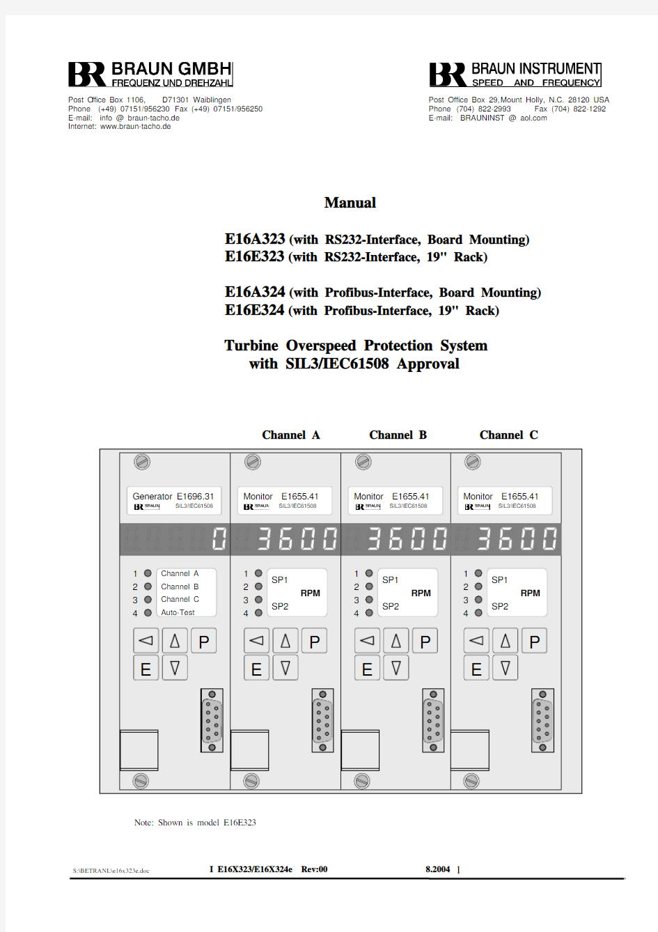
E16A323 (with RS232-Interface, Board Mounting) E16E323 (with RS232-Interface, 19" Rack)
E16A324 (with Profibus-Interface, Board Mounting) E16E324 (with Profibus-Interface, 19" Rack)
Turbine Overspeed Protection System
with SIL3/IEC61508 Approval
Generator E1696.31 Monitor E1655.41Monitor E1655.41 Monitor E1655.41
Note: Shown is model E16E323
Contents page Characteristics (3)
Function
Structure (3)
System
Speed Sensors (3)
Electronics (3)
System
Monitor E1655 (4)
Test Generator E1696 (4)
Alarms provided by the system (4)
Alarms (4)
Trip
Overspeed
Warning Alarms (4)
Channel
System Failure Alarms (4)
Modules (5)
E1655
Overspeed Setpoint (SP1) (5)
Sensor Failure Monitor (5)
Sensor Pulse Train Comparison (5)
Low Speed Check (SP2) (5)
External Trip Input (6)
Input (6)
Signal
Sensor
Sensor Signal Repeater (6)
Testing (7)
E1696 Generator (7)
Automatic test routine (7)
function (8)
Watchdog
Failure signals (8)
Display and Keys of E1696 (9)
Error-Messages of E1696 (10)
Display and Keys of E1655 (11)
Error-Messages of E1655 (11)
Programming of the modules (12)
parameters (12)
to
Access
Listing of E1655 (13)
Parameter
Parameters of E1655 (14)
Listing of E1696 (19)
Parameter
Parameters of E1696 (19)
Function Diagram (24)
Diagram (25)
Wiring
Rear View of 19"Rack (E-Version) (26)
Electrical
Specifications (27)
Dimensions of E-Version (19" Rack) (28)
A-Version (Board Mounting) (30)
Dimensions
of
Summary of Versions and Spare Part Recommendation (31)
Function Characteristics
Turbine Speed Monitoring against overspeed with redundancy by 3 independent channels with trip relay outputs 1 each per channel.
Function Test Facility with discrete selection by external signals, or automatic test routine with watchdog and system failure warning. 3 channel structure with independent monitoring modules
options for externally controlled test or automatic test routine
Each channel has its own comprehensive measurement and alarm section,
realized by a Monitor Module in each channel. Measurement is based on the
fast responding digital pulse interval principle with automatic floating number
of periods. Inputs include sensor monitoring. Each of the three Monitor
Modules ends up to an alarm outputs (breaking overspeed trip circuit). Any
failure of sensor or measuring function detected also sets the trip output of the
monitor to overspeed position. Further, each channel releases its own failure
warning signal, free available to the periphery as N/O contact.
The overall response to an overspeed condition is shorter than 15 millisec
(plus 1 pulse interval of the input pulse train).
fast response to overspeed
Each module within the system has its own data port at the front, usable for
the configuration of the module, and also for data calling. Available as RS232
(standard) or as PROFIBUS DP Interface.
Data interface facility
System Structure
(see also function diagram)
Speed Sensors
3 Hall-Effect based speed sensors series A5S... are placed at the turbine shaft
for a non-contact sensing of its rotational speed. Milled slots in the shaft, or a
pole wheel, form a profile to generate a pulse frequency corresponding to the
speed. The sensors have an incorporated signal amplifier providing an
adequate signal level for the transmission to the E16 Electronics.
Non-contact speed sensing
System Electronics
The E16 Electronics includes 3 Monitor Modules E1655, one each for each channel A, B, C. Further, 1 Test Generator Module E1696.
They are plugged into a card file, which is ready wired to perform the monitoring function. Terminal strips connect to the periphery. The System and its Modules
Monitor E1655
This module provides:
Sensor circuit monitoring and sensor signal lead monitoring, sensors pulse train comparison.
Sensor signal repeating output.
Digital speed measurement with display in RPM terms.
Overspeed trip setpoint (SP1) 2 alarm signal outputs,
also offering the facility of an external alarm control.
Low end setpoint (SP2) to perform the plausibility check,
with starter facility.
“channel warning alarm” relay output
"sensor failure alarm" relay output.
All functions are digital, with 5 digits resolution and accuracy of
+ 0.01% + 1 in the last digit.
Parameters are programmable from the front keys (with access lock), or via data interface.Functions included into the Monitor module E1655. Detailed description on following pages
Test Generator E1696
This module provides:
Adjustable frequency generator to substitute the sensor signal under test condition, with display in RPM terms.
Channel test selection by external control, or automatic test cycle with “System Failure” outputs. Functions included into the Test Module E1696
Detailed Description on following pages
Alarms provided by the System Overspeed Trip Alarms
The trip alarm of the monitor module E1655 within each channel will be released under one or more of these conditions:
1.overspeed setpoint (SP1) exceeded,
2.sensor failure detected (supply and signal lead monitor),
3.sensor signal voltage failure detected (only at zero speed)
4.sensor pulse train discrepancy detected,
5.low end setpoint (SP2) not exceeded after starter phase,
6.external alarm control actuated
7.self test failure conditions for channel trip alarm
Channel warning alarm
This signal contact, available from each channel to the periphery, breaks under one or more of these conditions:
1.overspeed setpoint (SP1) exceeded (if programmed).
2.external trip control actuated,
3.low end setpoint (SP2) not exceeded after starter phase
4.sensor pulse train discrepancy detected
5.self test failure of a neighbor channel. conditions for channel warning alarm
Sensor failure alarm
This signal contact, available from each channel to the periphery, breaks under one or more of these conditions:
1.sensor failure detected (supply and signal lead monitor),
2.sensor signal level failure detected. conditions for sensor failure alarm
System Failure warnings
The System Failure Alarms 1 and 2 , available as (N/O) contact will be signalized if one of the channels does not duly respond to the test procedure. see section Automatic Test Cycle for details of System failure warnings
The E1655 Modules
Alarms and Checks performed
Overspeed Setpoint (SP1)
The overspeed setpoint SP1 can be programmed to any speed level, in terms of RPM. Its setting can be called to display. Further programmable are the hysteresis width, and the event memory. If not memorized, the signal returns to “no excess” with the measurement decreasing below setpoint (minus hysteresis), otherwise it must be cancelled by an external acknowledge signal.
details of the overspeed alarm (SP1)
Sensor Failure Monitor
This function includes 2 sections, the sensor supply monitor and the sensor signal lead monitor. Both have certain preconditions, as explained below. They are met by all BRAUN sensors of series A5S... with push/pull output stage, possibly not by others. Check the sensor data sheet for validity. If not applicable, disengage the function.
The supply monitor checks the current drain, and the voltage of the sensor supply lead. Thereby it detects a break as well as a short circuit in the sensor connection. Obviously, this requires a sensor with adequate power consumption (>7ma).
The sensor signal lead monitor checks the level of this input to be either definitely on high or on low level, as a push/pull output is, if not broken. As primarily intended to monitor the signal lead in standstill state, the function automatically disengages when the sensor supplies a signal frequency. A failure thus detected will be memorized or not, as programmed.
Sensor Failure Monitor Sensor Pulse Train Comparison
This function checks for proper sensor signals during run of the machine. Each monitor Module E1655 compares the pulse train delivered from its own sensor to those of its both neighbor channels. If they differ, the monitor finds its own sensor to be faulty. This checks performs at any frequency, and does not depend on a speed measurement.
Active sensor signal check
Low Speed Check (SP2)
If the speed measurement drops below the (programmable) setpoint SP2 of the Monitor Module during operation, from whatever reason, a failure will be signalized. A very comprehensive check, including sensor and measurement function.
The level SP2 will be set at the low speed end, to 30 % for instance. For start-up, it will be overrun by the starter function of the E1655 module, activated by an auxiliary contact from the machine control, and held for a programmable period of time (0...999 sec) after its end.
This alarm is programmable to be memorized or not, or to be disengaged.
Low speed alarm checks for full performance
Display
The numerical display of the E1655 module serves as a programming aid (if not programmed by the data interface), indicating the program group number, the step number, and the parameter addressed.
When not in the programming phase, the display reads the actually measured speed, in terms of RPM or any other desired unit (also during the test phase). By pushbuttons, the setpoints SP1 and SP2 can be called (but not modified that way).
By red and green LEDs, the module indicates its alarm conditions for SP1 and SP2.
External Trip Input
In addition to the alarm and failure conditions as described before, the trip alarm may also be released by an external binary signal. This feature allows to include a condition from outside the speed monitor into the trip release, maybe a temperature signal, or a pressure contact. The high/low level for the response of this control input is adjustable. Trip release by external signal
Sensor Signal Input
The input accepts and feeds preferably 3-leads sensors, as BRAUN sensor
series A5S.. with p/p output. Others may give restrictions, in frequency range,
transmission distance, and the safety checks that can be performed.
By a control signal from the Test Generator Module, the monitor input is
switched to a second input, which receives the test frequency as emitted from
the Test Generator.
Sensor signal input
Sensor Signal Repeater
This isolated output repeats the signal as received from the sensor to the periphery. Feeds for instance a speed controller, or external display. The output is firmly tied to the sensor signal of the specific channel, not affected when the monitor is switched to the test frequency. Isolated sensor signal repetition
Testing with E1696 Test Generator Module Externally controlled test procedure
The E1696 provides a test frequency to be switched to the channels A, B, C of the system, one after the other, by means of external (DC) control signals. This frequency can be set (in terms of RPM) at the test generator, and then tuned up and down by pushbutton. The front display reads the actual frequency.
3 control inputs to the system are assigned to the 3 channels A,B,C. The one input held high switches its channel to test, substituting the sensor signal by the frequency of the test generator. Note: the repeater output of the module remains with the sensor input, not affected by the test procedure. The control inputs are locked against each other, to prevent of inadvertently switching 2 or 3 channel to test at the same time (this protection can be disengaged by program).
The channel under test reads the test frequency as received and measured at its numerical display (by RPM). If it exceeds its setpoint, it will signalize o-verspeed by its alarm relay and LED display.
A contact set of an external voter must signalize the correct response to the test generator. externally controlled test procedure
system reaction to externally controlled test
Automatic Test Routine
The Test Module repeats the automatic test routine with an adjustable time interval (1 ... 9 999 min).
The test routine itself is performed in three steps. With each step, the three monitors are tested subsequently.
Step one:
Simulated test speed 1 (n >SP1, feedback of tested channel must be trip), Step two:
Simulated test speed 2 (n Forced trip (n During step three, the monitor receives test speed 2. If measurement and alarming serve duly, the Monitor Module under test must release its trip alarm with step 1 at simulated test speed 1, but must not with step 2 at simulated test speed 2. With step 3 the forced trip input of the monitor is tested. At step 3 each monitor is switched to simulated test speed 2 (below overspeed) but the tested channel must feed back the trip signal. The Test Module checks for a corresponding response. It is returned from a contact set of an external device (magnetic valve). With an incorrect response from a channel, the routine immediately interrupts (to prevent the entire system of an unfounded overspeed trip alarm to the machine) and a system failure signal is released. The Test Module throws the faulty channel into its overspeed condition (by means of the forced trip input). Thus, the overspeed safety is maintained – the system now responds with a 1 of 2 characteristics, in other words, if just one other channel detects overspeed or an internal fault, the turbine will be shut down. regularly performed automatic test routine: checking the response of all channels to 2 test frequencies safety maintained after failure in one channel Watchdog Function The watchdog section on the E1696 module performs an identical test step sequence, independent from the above but in close synchronism. If both, test routine and watchdog are not at the same step at the same moment, system failure is signalized. But more, the above mentioned measure of forcing a faulty channel to its overspeed condition also requires the said coincidence between routine cycle and watch dog. In other words, the measure is taken only if the stepping sequence up to this moment was correct. This prevents the system from an unfounded overspeed alarming, and thus further increases the reliability, and the availability of the machine. Incorrect stepping however generates a warning, by the System Failure alarm output, which should immediately be observed. watchdog checks for correct stepping sequence and crosschecks trip signals Failure signals to the periphery The Test Generator Module E1696 provides failure signals (1) and (2), as N/O relay contacts, de-energized to announce a failure, also with power supply missing. Both respond to an alarm from one or more of the channels A, B, C, and to a failure detected in the testing sequence, or to an incorrect performance of one of the Monitor Modules during test. system failure signals from test and watchdog section Display and Keys of E1696 During auto test sequence Generator E1696 LED2: flashing = channel B is tested On = channel B signalizes trip LED3: flashing = channel C is tested channel C signalizes trip LED4: On = Auto-Test-Mode active Off = Manual-Test-Mode active In normal operation the display reads: With key the value of test speed 1, with key the value of test speed 2. With keys and depressed : the remaining time (XXXX.X minutes) until the next auto test sequence is started Start of an auto test sequence An auto test sequence can be manually started by depressing keys and . Reset of latched alarms with key . Display (error) messages refer to next page. Error-messages of test generator E1696 During normal operation: C0-E1 : channel A signalizes trip, B and C not C0-E2 : channel B signalizes trip, A and C not C0-E3 : channel A and B signalize trip, C not C0-E4 : channel C signalizes trip, A and B not C0-E5 : channel A and C signalize trip, B not C0-E6 : channel B and C signalize trip, A not During an auto-test-sequence: C1-E1 : incorrect feedback of channel A at simulated test speed 1 C2-E1 : incorrect feedback of channel B at simulated test speed 1 C3-E1 : incorrect feedback of channel C at simulated test speed 1 C1-E2 : incorrect feedback of channel A at simulated test speed 2 C2-E2 : incorrect feedback of channel B at simulated test speed 2 C3-E2 : incorrect feedback of channel C at simulated test speed 2 C1-E3 : incorrect feedback of channel A at test of forced trip C2-E3 : incorrect feedback of channel B at test of forced trip C3-E3 : incorrect feedback of channel C at test of forced trip C9-E1 : channel A not ready for test C9-E2 : channel B not ready for test C9-E3 : channel A and B not ready for test C9-E4 : channel C not ready for test C9-E5 : channel A and C not ready for test C9-E6 : channel B and C not ready for test C9-E7 : channel A, B and C not ready for test Error-Messages from E1696 (C = Check, E = Error) Other display-messages FC-1 : test of forced trip SELF : E1696 performs a self test routine (subsequent to each auto test sequence) FC = Function Check Display and keys of E1655 Monitor E1655 In normal operation the display reads With key the value of SP1, with key the value of SP2. Error messages (SE = Selftest-Error, CE = Check-Error) SE-01: sensor supply failure or sensor lead failure, SE-02: pulse train difference, SE-03: SE-01 and SE-02 simultaneously, SE-04: low end failure, SE-05: SE-01 and SE-04 simultaneously, SE-06: SE-02 and SE-04 simultaneously, SE-07: SE-01, SE-02 and SE-04 simultaneously. SE-10 : test speed of generator = zero (= failure of test generator) or test time exceeds 10 minutes (= failure of test generator) or neighbour channel signalizes permanent self test (= failure of neighbor channel) SE-20 : neighbour channel fails to produce self test within 5 hours time of operation (= failure of neighbor channel) CE-1 : monitor switched to forced trip by E1696 Reset of latched alarms with keys and . Other display-messages : (FC = Function Check) FC-1 : test of forced trip by E1696 FC-2 : external trip control actuated SELF : self test of monitor (periodically repeated after each 2 hours) Programming of the modules Access to parameters Principle: Select a Parameter by it's "Name" Pgg.ss, where gg = Parameter- Group-No. and ss = Step-No. within Group, then verify the value and change it according the application Programming: To enter the programming phase, press both keys and simultaneously; instead of normal display, P00.00 will be shown. Select group- or. step-no. with keys , . Toggle between group- and step-range with key . Show parameter's value with key . Select (move ) active digit with key . Adjust figure in active digit with keys , . Acknowledge with key , Cancel (old value still valid) with key . Return to normal operation with key Example: change value of parameter P01.01 from 2386 to 2387 or 2385: Enter = new, changed value is valid Parameter listing of Monitors E1655: Summary of programming steps and their initial parameters (default values) as set on delivery program- data set on delivery Step No. parameter function (initial data) P00 .00 access code request 0000 .01 new code figure 0000 .02 lock status (1 = unlocked, 0 = locked) 1 = unlocked P01 .00 input: scaling decimals of input signal frequency 0 = none .01 value of nominal input frequency (Hz) 10000 .02 decimals of corresponding speed 0 = none .03 corresponding speed (unit as desired) 10000 .04 low end of speed range 00001 P02 .00 zeroed LSDs in display 0 = none .01 display updating sequence (X.X sec) 0.3 (sec) .02 time elapse of starter phase (XXX sec) 000 (sec) .03 truth-level of external trip signal (0 = low, 1 = high) 1 = high .04 sensor monitoring (0=off,1=on,2=on,latched) 1 = on .05 mode of sensor monitoring (0=none,1=current,2=voltage,3=both) 1 = current .06 lowspeed monitoring (0=off,1=on,2=on,latched) 1 = on .07 sensor signal deviation monitoring (0=off,1=on) 0 = off .08 reset interval of deviation counters (1....9999 pulses) 1000 .09 allowable deviation between counters (0...99 pulses) 50 .10 limit of error counter (1...99 deviation detections) 5 .11 warning alarm at overspeed (0=no,1=yes,2=yes and at test overspeed) 1 = yes P03 .00 setpoint (SP1) in unit as programmed for display 10000 .01 hysteresis bandwidth SP1 (XX.X % of SP1) 05.0 (%) .02 alarm to be latched (0=no, 1=yes) 0 = no P04 .00 setpoint (SP2) in unit as programmed for display 00100 .01 hysteresis bandwidth SP2 (XX.X % of SP2) 05.0 (%) .02 alarm to be latched (0=no, 1=yes) 0 = no P05 .00 hardware address added to device address (0=no,1=yes) 0 = no .01 device address (range 1...125) 001 Parameter Group P00.xx of E1655: Data Access, Password Key figure to access Programming access to all parameters can be locked by a password number. If not properly served, the parameters may be called to display but not varied. If not properly served, the display reads -E1-,and any programming in a later program step will be rejected. Note: If the knowledge of the password number went lost it may be recalled to display by a procedure, as described in a separate sheet K0-095 (not included into these instructions). The code figure then appears by 4 digits. In a subsequent program step, a new code may be established, substituting the one previously valid. The key function may be disengaged by a next program step. With authorized access, set parameter to 1 in step No .02, to generally unlock the key. This may prove practical during the installation phase to facilitate the adjustments. Once installed, the key function should be reactivated, by programming parameter 0 in this step. Step P00.00: Code figure to access Step P00.01: new code figure Step P00.02: unlock access key Parameter Group P01.xx of E1655: Measurement Configuration, Scaling I nput Scaling defines the relation between the input signal frequency (in terms of Hz), and the corresponding display (in terms of RPM). Both values are freely programmable by their decimals and numerical amount. Of course, they must refer to the same operation level. This reference point is recommended close to the high end of the intended operation range. In later operation however, it may be overrun without error. Scaling Example The speed is measured by a contactless probe scanning a gear wheel on the turbine shaft with 90 teeth. Thus, a speed of 3000 rpm results in a signal frequency of 3000x90:60 (Hz) = 4500 (Hz). With this as the reference level, the following parameters are to be set: Step P01.00 parameter 0 (= no decimals) P01.01 parameter 04500 P01.02 parameter 0 (= no decimals) P01.03 parameter 03000 scaling input signal frequency (Hz): Step P01.00 = number of decimals, Step P01.01= value. corresponding value of rpm: Step P01.02 = number of decimals, Step P01.03 = value Low end for shut-off If the speed falls lower than this level, the measurement will be cancelled to zero. The low end is programmed by the same terms, as defined for the speed by steps P01.02 and P01.03. Step P01.04 low end of operating range Parameter Group P02.xx of E1655: Display, Starter time, Failure Monitoring LSDs on zero If the display of the speed uses 4 or more digits, for application reasons, the lesser significant digits (LSD) may appear fluctuating. To avoid irritations by not significant digits, a number of them may be permanently kept at zero. Set the parameter to the number of LSDs to be kept on zero. Step P02.00: zeroing LSDs Display updating sequence Independent from the response time used for other functions, the display may have its own up-dating sequence - again in the interest of stabilized and well legible readings. Set the parameter to the time in steps of 0.1 sec. A recommended value is 0.3 sec. Step P02.01: display updating Starter time period This step sets the starter time period (elapse). Starter phase state for SP2 lasts from the beginning of the external starter signal plus the programmed time elapse following its end. Range 000...999 sec. Step P02.02: starter time elapse Truth level of External Trip Signal To match the control source, and specific safety aspects, the parameter of this step defines either high or low signal level to make the condition true. Step P02.03: Truth level of External Trip Signal parameter 0 : high = control true 1 : low = control true Enable/Disable of sensor failure detection Sensors without power supply (for example inductive sensors) cannot be monitored against failure. If the sensor is monitored, it is possible to latch a failure alarm until it is reset. Step P02.04: Monitoring of sensor parameter 0 : off 1 : on, alarm not latched 2 : on, alarm latched Mode of sensor monitoring The sensor can be monitored versus current drain (alarm if current drops below 7 mamps or exceeds 150 mamps) and/or signal voltage level during zerospeed of the turbine. Note: Signal voltage level monitoring only possible with BRAUN sensors with incorporated push/pull output (series A5S...). Step P02.05: Mode of sensor monitoring parameter 0 : no monitoring 1 : current monitoring 2 : voltage monitoring 3 : current and voltage Lowspeed monitoring (n < SP2) The lowspeed monitoring can be switched off. If the lowspeed monitoring is enabled, the speed of the turbine must exceed SP2 (after starter time has elapsed). Step P02.06: lowspeed monitoring parameter 0 : off 1 : on, alarm not latched 2 : on, alarm latched Sensor Pulse Train Comparison Purpose of this function: ?Detection of a faulty position of the sensor (cleareance to big or wrong angular position) during starter phase of the turbine (n Function principle: The pulses of all three sensors are counted in each monitor. The main sensor of the monitor is detected as faulty if the main counter deviates from both neighbour counters. The allowable deviation between the counters is adjustable. The counters are periodically reset after an adjustable number of pulses or if a fault is detected. Subsequent counter evaluations that indicate a faulty sensor increase an error counter. This counter is reset by an evaluation that indicates a proper working sensor. If the error counter exceeds an adjustable limit, the alarm is released. Programming steps for deviation monitoring: Step P02.07 : monitoring on/off Step P02.08 : number of pulses for periodically reset of counters (range from 1 to 9999 pulses) Step P02.09 : allowable deviation between counters (range 1 to 99 pulses) Step P02.10 : limit of error counter (range from 1 to 99) Example: P02.07 set to 1 (monitoring on) P02.08 set to 1000 (counters will be reset after 1000 pulses, of any sensor) P02.09 set to 50 (allowable deviation of 50 pulses within 1000 pulses) P02.10 set to 5 (5 subsequent error detections until alarm is released) With above settings a non operational main sensor will be detected after 250 pulses of the other two sensors (5 error detections after 50 pulses). Step P02.07: sensor pulse train comparison on/off parameter 0 : off 1 : on Step P02.08: number of pulses for reset of pulse counters range 0001 to 9999 pulses Step P02.09: allowable deviation between counters until error counter is increased range 01 to 99 pulses Step P02.10: limit of error counter until alarm is released range 01 to 99 Warning alarm at overspeed condition It can be programmed whether the warning alarm will be released at a real overspeed condition or additionally at a test overspeed condition. Step P02.11: warning alarm at overspeed parameter 0 : no 1 : yes, only at real overspeed 2 : yes, at real and test over- speed Program Range P03.xx of E1655: Defining the Overspeed Alarm SP1 Overspeed setpoint The setpoint SP1 is programmed in the same terms (rpm) as selected for the display of the speed (in step P01.03). Alarm Hysteresis The hysteresis is the margin between condition "excess" (>) and "no excess" (<), defined by its bandwidth.. The hysteresis bandwidth is set as a percentage of the setpoint. Setting in step P03.01. The position of the hysteresis is firm at below the setpoint. Example: At a setpoint of 10000 rpm and a hysteresis of 5%, an overspeed alarm is released at a speed exceeding 10000 rpm and is reset at a speed less than 9500 rpm. Overspeed alarm latched An overspeed alarm can be latched Step P03.00: overspeed setpoint Step P03.01: band width of hysteresis of SP1 Step P03.02: overspeed alarm latched parameter 0 : no 1 : yes Program Range P04.xx of E1655: Defining the Lowspeed Alarm SP2 Lowspeed setpoint The setpoint SP2 is programmed in the same terms (rpm) as selected for the display of the speed (in step P01.03). Alarm Hysteresis The hysteresis is the margin between condition "excess" (>) and "no excess" (<), defined by its bandwidth.. The hysteresis bandwidth is set as a percentage of the setpoint. Setting in step P04.01. The position of the hysteresis is firm above the setpoint. Example: At a setpoint of 100 rpm and a hysteresis of 5%, a lowspeed alarm is released at a speed of less than 100 rpm (not in starter state) and is reset at speed exceeding 105 rpm Lowspeed alarm latched A lowspeed alarm can be latched Step P04.00: lowspeed setpoint Step P04.01: band width of hysteresis of SP2 Step P04.02: lowspeed alarm latched parameter 0 : no 1 : yes Parameter Group P05.xx of E1655: Defining Data Interface Parameters (only relevant for PROFIBUS) Further details of Profibus-Interface see instructions I E16Pro1e. Slot position address added/not added to device address Each slot for the monitors has a hardware wired address adder on the backplane: L09 (monitor channel A) : address 1 L17 (monitor channel B) : address 2 L25 (monitor channel C) : address 3 It is programmable that the programmed address in step P05.01 automatically increases by this channel specific adder No. Thus, the entire system with all monitors and the testgenerator of one rack (including the spare parts) can be set to the same basic address. Example: P05.01 system address set to 92 Test generator has address 92 Monitor channel A (slot L09) has address 93 Monitor channel B (slot L17) has address 94 Monitor channel C (slot L25) has address 95 For the operation of the Profibus-Interface each device must have an address, range from 001 to 125. The address is set in step P05.01. Step P05.00: hardware address added to P05.01 parameter 0 : no 1 : yes step P05.01: device No Parameter listing of Test Generator E1696: Summary of programming steps and their initial parameters as set on delivery program- data set on delivery Step No. parameter function (initial data) P00 .00 access code request 0000 .01 new code figure 0000 .02 lock status (1 = unlocked, 0 = locked) 1 = unlocked P01 .00 scaling: decimals of signal frequency 0 = none .01 value of nominal signal frequency (Hz) 10000 .02 decimals of corresponding variable 0 = none .03 corresponding speed (RPM) 10000 P02 .00 simultaneous test of two channels possible (0=yes,1=no) 0 = yes .01 automatic resume of auto-test after sensor failure alarm (0=no,1=yes) 0 = no .02 repeating time period of auto-test-sequence (1...9999minutes) 10 .03 test mode (0 = automatic, 1= external) 0 = automatic .04 simulated test speed 1 (RPM) 11000 .05 simulated test speed 2 (RPM) 09000 P03 .00 device No (for Profibus-Interface) 001 Parameter Group P00.xx of E1696: Data Access, Password (identical to Monitors E1655) Key figure to access Programming access to all parameters can be locked by a password number. If not properly served, the parameters may be called to display but not varied. If not properly served, the display reads -E1-,and any programming in a later program step will be rejected. Note: If the knowledge of the password number went lost it may be recalled to display by a procedure, as described in a separate sheet K0-095 (not included into these instructions). The code figure then appears by 4 digits. In a subsequent program step, a new code may be established, substituting the one previously valid. The key function may be disengaged by a next program step. With authorized access, set parameter to 1 in step No .02, to generally unlock the key. This may prove practical during the installation phase to facilitate the adjustments. Once installed, the key function should be reactivated, by programming parameter 0 in this step. Step P00.00: Code figure to access Step P00.01: new code figure Step P00.02: unlock access key Group P01.xx of E1696: Scaling the Generator Scaling defines the relation between the signal frequency (in terms of Hz), and the corresponding display (in terms of rpm). The values for the steps P01.00 through P01.03 have to be set identical to the steps P01.00 through P01.03 of modules E1655. Example: A signal frequency of 4500 Hz corresponds to a speed of 3000 RPM. Program as follows: in step P01.00 parameter 0 in step P01.01 parameter 04500 in step P01.02 parameter 0 in step P01.03 parameter 03000 Step P01.00: Decimals for input frequency Step P01.01. Signal frequency at reference Step P01.02: decimals for display Step P01.03: speed value at reference Group P02.xx of E1696: Adjustments for test mode Protection against inadvertent overspeed trip during manual test phase If two or three channels are switched to test simultanously, the system will release an overspeed trip alarm. As a protection against an inadvertent release the channels can be locked against each other. If the lock is enabled, it is not possible to switch more than one channel to test at the same time. If two or three channels are selected at the same time, no test occurs at all. Setting in step P02.00: Parameter 0 : simultanous test of two channels possible (overspeed trip) Parameter 1 : simultanous test not possible Step P02.00: Protection against inadvertent overspeed trip during manual test phase Automatic resume of auto-test after failure alarm of monitor If an monitor alarm occurs, the auto-test is inhibited and the system failure alarms 1 and 2 are released. With parameter 0 in step P02.01 the system failure alarm must be externally canceled, with parameter 1 it resets automatically (as soon as the monitor alarm is no longer present) and the auto- test performance is resumed. Step P02.01: Automatic resume of auto-test 0 = no 1 = yes Time repeating period inbetween auto-test –sequences The time is adjustable from 1 to 9999 minutes. Step P02.02: Time repeating period inbetween auto-test-sequences Range 1 to 9999 minutes Manual external or automatic test mode On manual test mode the channels are selected to test by an external control signal. The simulated test speed is adjustable at the generator by the front keys. On auto test mode the programmed simulated test speed 1 and simulated test speed 2 are active. Step P02.03: Manual or automatic test mode Parameter 0 : automatic test mode 1 : manual external test mode Simulated test speed 1 and simulated test speed 2 Simulated test speed 1 must be set to a value above the trip setpoint (SP1 of E1655), simulated test speed 2 must be set to a value below the trip setpoint SP1. Example: SP1 of E1655 is set to 3300 RPM Simulated test speed 1 is set to 3350 RPM, Simulated test speed 2 is set to 3250 RPM. Step P02.04: Simulated test speed 1 Step P02.05: Simulated test speed 2 中央新风系统 一、定义 中央新风系统:就是实现建筑物室内外空气一年365天,一天24小时不间断循环置换的集中控制系统。其能科学定义和组织室内空气流动路径,使室外的新鲜空气经过滤后源源不断送入室内,污浊的空气有组织、及时地排至室外。 VMC(自平衡式中央机械通风Ventilation Mecanique Controlee)住宅通风三原则: (1)通风路径(室外新风—卧室/客厅—走廊/过道—卫生间—排到室外) (2)通风风量(室内需要风量,两种算法) (3)通风时间(24小时不间断) 分析:(1)一般每个卧室配一个新风口,排风口与之对应或几个房间集中排风 (2)两种算法取其大 算法一Q1=人均新风量*室内人数(人均新风量≧30m3/h) 算法二Q2=每小时换气次数*室内有效容积(民用建筑换气次数从经济性考虑可按每小时~次计,而 商用区域一般按2~5次计) 举例: Dee Fly Compact最大适用面积(按次/小时,房高米) 195=**M M = 195/(*)= 125㎡(150~200) 以上通风面积厨房,卫生间,阳台不计在内 当单独设置新风系统,且换气量较大时,应充分考虑新风对采暖负荷和空调负荷的影响, 从节能的角度考虑,建议选用全热交换新风机组。 设计上有几个原则要注意: 1.室外进风口到风机的部分要尽量保证笔直,否则滤网会更快造成局部被堵住,然后形成较大阻 力。 2.室外的进风口和出风口要尽量的远。 3.室内的回风口到风机部分的管道要尽量短。 4.同一房间内的送风和回风口要尽量远离。 5.管道尽量笔直。 6.管道弯曲之前尽量保证至少1米的笔直部分。 7.卫生间和厨房绝对不要装回风/送风口,应该使用普通的排气扇/抽油烟机而不是连续的换气系 统。 8.尽量把风机放在厨房或者卫生间。 二.分类 1 .功能分 (1)单向流新风系统:安装在吊顶内的风机通过管道与一系列的排风口相连,风机启 动,室内混浊的空气经安装在室内的吸风口通过风机排出室外,在室内形成几个有 效的负压区,室内空气持续不断的向负压区流动并排出室外,室外新鲜空气由安装 在窗框上方(窗框与墙体之间)的进风口不断的向室内补充。 新风系统的施工安装技术方案 1、施工前准备 包括供货、预约施工时间及现场施工交底工作。 1)供货:本地客户供货有两种方式:客户自提、公司配送。 2)预约施工时间:配送货完成后,有施工监理人员根据信息与客户预约具体的施工时间。 a、人员的配备:与工队长提前沟通施工人员及开工时间; b、工具的准备:施工过程中的工具工人自带,防止因为工具问题耽误工期,需要公司配合的应提前申请。 3)、客户准备:客户为进行新风系统的施工进行相关的协调工作,如物品清理、物业进出、水电齐备等。 4)现场施工交底:是施工监理、施工负责人与客户说明,针对现场情况及安装基本原则提出合理化方案,征得客户同意后进行施工。 2、主机吊装 主机是新风系统中的核心部件,是系统发挥作用的动力源,也是唯一可能出现噪音的部件。主机的吊装要科学谨慎。 1)主机安装前必须检查外观尺寸、性能参数,是否适用于本安装环境。检查风机叶轮与机壳间的间隙和风扇转动是否符合要求,箱体内应无杂物。 2)吊装主机的原则:主机排风出口可直通风道或者室外。机器距离风道不宜过短(小于0.5米),进入通风竖井的管道不应太长,以通风竖井内长的1/5为宜。机器安装最好能直连风道(或室外排气口),应尽量没有弯度以减少阻力。主机安装应牢固、水平,吊杆螺母必须有防松和减震措施,保证安全牢固无振动。在主机吊装位置下方的吊顶,必须留有大小合适的检修口,安装位置应便于安装与检修保养。 3、管路排布 在一套新风系统的安装过程中,管路的排布是非常关键的部分,因为管路的排布会影响到系统风量损耗、系统噪音等多个方面。 a、一般要求 (1)通风管径尺寸应根据主机接口大小、风量大小及风压进行合理选择,通风管道规格的检查,风管以内径为准,其配件以外径为准(2)圆形风管的斜插式三通或四通,其夹角宜为15°~60°,夹角的允许偏差为不大于3°。 德国博朗耳温枪4520 博朗BRAUN耳温枪是全球婴幼儿测温第一品牌! 最多医生诊所及妈妈推荐!美国几乎所有的儿科医生都用博朗体温计,目前国使用博朗4520的医院有瑞金医院,儿童医院等等. 传统的水银温度计,在一些国家已经禁用,水银温度计的优点是测温准确,但其缺点更为明显,水银(金属汞)为有毒重金属,挥发性强,一旦打碎后,因为它半固体半液体的特征,无法完全清理,水银的挥发将导致吸入体,对健康构成长期的威胁。 电子体温计很好的解决了水银温度计的缺点,但应用在宝宝身上可就难以操作了,几乎没有一个宝宝能够接受一个探头长达2分钟以上的刺激,大概只有等宝宝睡着了,才能正常的测温。 现在好了德国博朗”一秒耳温计”,只需往宝宝耳朵里一放,一秒钟不到,温度多少立刻精确显示,不论躺着还是坐着都可以用,孩子无痛苦! 德国博朗4520耳温计是BRAUN系列产品的最高端型号一秒体温计,人体工程学外型,手感舒适.全新护耳柔垫设计,更小的测量口径,柔软而温和,更适合婴幼儿,为你的全家健康保驾护航! ?舒适适合全家大小使用,最温和的体温测量工具; ?安全全新设计柔软侦侧头,安全不伤耳道; ?快速测量体温,仅需一秒; ?准确经医院使用测试证明,测温准确. ?一秒八次测温–耳套检测警示 ?Flexible tip(4000 系列独有)柔软弹性探头 ?更小测量口径,测量更准确 ?耳套自动弹出装置 ?贴心凸纹按钮设计,测量不滑手 ?保留前8次温度记忆 ?ExacTemp技术(4000系列独有)配合回馈系统:有指示灯光和声音提示测得正确温度,提示是否没有正确放置. ?使用时间更长 1.产品包装清单一个硬盒保护安放支架+送的21个耳套+耳温计一个+5号电池两节 2.电池说明刚买的产品中含有电池,但是电量不是很足,可以用1-2个月,建议1-2月后换电池,电池是5号电池。 3.几个按键说明 ?I/O:按一下开机,长按就是关 ?start :测量前按一下,灯会闪烁,表示进入测量的状态了。 4.怎么开机关机 ?开机:按‘I/O’键 ?关机:再长按‘I/O’键就关机了(会出现OFF提示);或者不进行操作,机器会自动关机。 5.华氏度转换摄氏度的方法 ?本品采购自美国,美国人对温度的显示是华氏,按”I/O”开机按钮,在右下角有个”F”的标志,那就表示当下使用状态是在华氏状态。 ?在关机的状态下,同时按住‘I/O’键和‘start’键不动,等待画面依次显示“F”“set”“℃” 当显示到℃的时候同时松手就可以了。再开机,就是摄氏度状态了,看看右下角是不是变成了“℃”,这样就是摄氏度了。 6.怎么方便的使用耳温计 ?将温度计从盒中取出,并装上一个耳套。 我国新风系统应用现状 由于可通过置换和过滤空气的形式确保室内空气清新,新风系统日渐得到消费者的青睐。2008年以来,厚积薄发的新风行业日渐红火起来。“美的”、“格力”等家电领域的大牌企业纷纷将业务拓展至新风系统的研发和生产,房地产开发商也纷纷将新风系统打造成自己楼盘的新卖点,从事新风系统工程施工的企业也日益增多,新风行业正在进入一个高速发展的快车道。 自2008年开始,上海布朗环境技术有限公司(以下简称“布朗”)有关新风系统的销售业绩一直在以每年30%~50%的增速快速增长。布朗新风系统已在“万科”、“保利”、“绿城”等多个房地产企业的项目中得到应用。据该公司销售总经理蔡一敬介绍,一次性使用了几千套布朗新风系统的房地产项目已越来越多,新风系统的应用领域也正在从商用领域向民用住宅领域蔓延。 据知情人士分析,布朗在新风系统的上述应用状况,其实是整个新风系统目前应用状况的一个缩影。新风系统正迎来其良好的发展机遇。 “新风”应用渐成风 从单纯应用于商用领域,到进入寻常百姓家,新风系统在我国大面积推广的时间尚不足十年。其快速发展的态势就连一些原先就看好该行业发展前景的业内人士也始料未及。目前,随着城市空气污染的加剧以及人们对生活质量的重视,利用新风系统来创造更加舒适的家居环境已渐成风潮。受此影响,主动采用新风系统的房地产开发商、从事新风系统生产和安装的企业日渐增多。 据了解,在2008年以前,新风系统在我国房地产项目中的应用率并不高,只有“万科”、“保利”、“绿城”等一些比较高端的、敢吃螃蟹的房地产企业率先在自己的楼盘里应用了新风系统。而今,除上述企业之外,“当代”、“朗诗”、“北京K2”等一大批房地产企业都已在自己的楼盘里应用了新风系统。类似“户式新风”、“大宅鲜氧生活”、“恒温恒湿恒氧”、“国际级中央新风系统”等词语在各个房地产楼盘的宣传语中屡见不鲜。目前,不管是技术稍微简单的单向流新风系统还是技术略微复杂的双向流新风系统,它们在房地产项目中的应用量日渐增多。据布朗在辽宁的代理商王芳介绍,目前单向流新风系统在沈阳市的中高档楼盘中已经得到普及,双向流新风系统在沈阳市高档楼盘里的应用率也非常高,沈阳市的房地产精装修项目基本上都配有双向流新风系统。 房地产开发商和消费者对新风系统的青睐使得新风系统安装行业的行情非常火爆,一些以前从事其他家装设备安装的企业争相将自身的业务范围延伸到了新风系统的安装领域。原本从事地暖系统施工的辽宁华源暖通工程有限公司于2010年开始涉足新风系统安装行业,目前该公司在新风系统安装领域的工程量已经达到了30多万平方米。比辽宁华源暖通工程有限公司稍早,北京安恒信达有限公司于2008年就开始涉足新风系统工程领域,并于2010年成功中标北京K2地产一期共计1500套中央新风系统工程,开创了北方地暖施工企业中标此类工程的先例。如今,北京亚特伟达冷暖节能工程技术有限公司、重庆温馨时代暖通设 博朗耳温计说明书 1.产品包装中都有哪些东西打开包装产品共有3样东西:一个硬盒保护安放支架+送的21个耳套+耳温计一个 2.产品所用电池说明刚买的产品中含有电池,但是电量不是很足,可以用1-2个月,建议1-2月后换电池,电池是5号电池。 3.几个按键说明I/O:按一下开机,长按就是关start:测量前按一下,灯会闪烁,表示进入测量的状态了。 4.怎么开机关机开机:按‘I/O’键就??关机:再长按‘I/O’键就关机了(会出现OFF提示);或者不进行操作,机器会自动关机。 5.华氏度转换摄氏度的方法 由于产品是美国货,美国人对温度的显示是华氏,按”I/O”开机按钮,在右下角有个”F”的标志,那就表示当下使用状态是在华氏状态。 中国人都是用摄氏度,怎么调呢? 在关机的状态下,同时按住‘I/O’键和‘start’键不动,等待画面 依次显示“F”“set”“℃”当显示到℃的时候同时松手就可以了。再开机,就是摄氏度状态了,看看右下角是不是变成了“℃”,这样就是摄氏度了。 6.怎么方便的使用耳温计将温度计从盒中取出,并装上一个耳套。 按照上面的描述,转换成摄氏度测量状态按I/O键启动机器,把探头轻柔缓慢地伸入耳道。按下“Start”按钮,然后松开。Start按钮上方的 绿色Exactemp灯开始闪烁,显示正确的探头就位。等待听见提示音以及绿色Exactemp灯信号固定不动,表示已经以正确的方式结束测量,可以拿下体温计,读数。按住”I/O”按钮,直到显示“1MEM” ,可以依次显示最近八次测量的温度。耳温计关闭时,按住”I/O” 按钮约5秒钟(会出现OFF提示)或者不进行操作机器会自动关机。 7.多少温度是正常? 0-2岁36.4-38度都算正常 3-10岁36.1-37.8度都算正常 11-65岁35.9-37.6度都算正常 65岁以上35.8-37.7都算正常 8.有温差怎么办? 可能您连续测了几次,前后有一点偏差,这个不需担心,4520有0.1的温差,同时要确保2次测的地方和方法都是正确的。2次测量的时间间隔最好在1分钟以上,因为人的手是有温度的,会影响耳温计的测算温度。 9.一个耳套可以用多长时间? 一个耳套可以用6-8次,不需要一次一换,太浪费;不同的人建议用不同的耳套,这样比较干净点,也比较讲究。 用酒精和棉花擦拭耳套,可以增加耳套使用次数 10.为什么在耳朵测量? ⑴腋下温度测量的只是表皮的温度,因此不能可靠地反映核心体温 ⑵口腔温度受饮水、进食和呼吸的影响 Series 9 9 6 13 English 21 1 2 A Series 7 6 新风——BLLC布朗 新风系统 新风系统是由风机、进风口、排风口及各种管道和接头组成。安装在吊顶内的风机通过管道与一系列的排风口相连,风机启动,室内受污染的空气经排风口及风机排往室外,使室内形成负压,室外新鲜空气便经安装在窗框上方(窗框与墙体之间)的进风口进入室内,从而使室内人员可呼吸到高品质的新鲜空气。 要点 1.独立排风管形式——节省了竖井风道占用的室内空间,户间相互影响小。 2.顶部不设排风机,公用竖向排风道形式——易发生回流和泄流现象。 3.顶部设排风机,公用竖向排风道形式 1)每户都在厨房或卫生间设置排风机,排风机出口接公用竖向排风道; 2)每户都不设置排风机,厨房和卫生间排风出口接公用竖向排风道。 优势 1)不用开窗也能享受大自然的新鲜空气; 2)避免“空调病”; 3)避免室内家具、衣物发霉; 4)清除室内装饰后长期缓释的有害气体,利于人体健康; 5)调节室内湿度,节省取暖费用; 6)有效排除室内各种细菌、病毒。 背景 在北欧斯堪的那维亚地区在讲究质量和能源节约的国家里,中央新风系统(VMC)存在至今已有50年历史了。70年代西班牙90%以上的新建住宅中装用VMC系统。1989年美国ASHRAE制定了“室内空气品质通风规范”。在德国,住宅通风系统已经与建筑物溶为一体,成为不可缺少的重要组成部分。2000年,欧盟统一了住宅通风标准。在中国2002年1月1日室内空气污染控制规范诞生。非典、禽流感、肺结核等疾病的发生,使全世界对室内空气质量给予了高度的关注。 类型 1.单向流负压新风系统 2.双向流新风系统 3.全热交换新风系统 4.地送风系统 布朗 BLLC ,来自于全球500强企业——IMG 集团,北美最大的节能系统制造集团及控股机构。具有百年专业研发及制造历史,同时其尖端的室内空气技术为美国军方及航空机构服务。全球IQA (室内空气品质)行业的领导者。旗下主要品牌:B/L 、BLLC 、TITON 。 B&L 博仕莱 BLL 布朗 TITON 泰顿 关于BLLC 布朗 1932年,亨利·布朗先生研制并生产了一种安静高效的厨房通风设备,命名为摩特德,这一举措成就了今天的BLLC ,是世界最大的室内空气质量(IAQ )系统产品制造商, 其中最为突出的是Guardian Plus 系列IAQ 产品:在2002年全球建筑展览会上,荣获“住宅技术创新奖”,同时,荣获美国ADEX “产品设计优秀奖”。创立了新一代室内空气质量系统的标准。 它所提供的IAQ 和建筑气候系统让人们在健康、洁净的居住环境中生活,着力解决长久以来开窗通风-破坏节能,关窗密闭-损害健康这样的建筑矛盾。 获取并应用空气中大量的自然能源---空气能(可再生能源)同时对建筑内的能量进行 我们常常说“睡上一觉就好了”,睡眠是消解疲劳、补充体力的至好方式,每天充足的好睡眠是良好生活的有力保障。睡眠的时候,人体对新鲜空气的需求与其重要,好的睡眠环境才能确保睡眠质量。卧室里安装新风机能够为人体补充睡眠所需的充足氧气。那么,卧室新风机十大品牌排名哪个好呢?我们今天就来看一看。比较受消费者欢迎的壁挂式新风系统十大品牌,介绍10个优秀品牌和出色的产品。 本文主要探讨纯新风量在100立方米每小时以内、适合卧室使用的壁挂式新风机。看看下面这些卧室壁挂式新风机十大品牌,你觉得哪个更适合在自己家里安装? 1、松下Panasonic (日本),机型:FV-RZ09VD1 松下是多种电器行业的著名品牌。在中国新风系统市场上,松下也许属于第/一大品牌,主要是因为吊顶式新风系统很受欢迎。出于对国际知名品牌的向往,虽然松下的壁挂式新风机外观有点过时,但还是有不少消费者在购买新风系统时只考虑松下品牌。 纯新风量:90m3/h 价格:9980元 尺寸:71*38*20cm 优点:静音运行,品牌知名度高。 缺点:外观设计档次低,体积大,价格高。 2、埃尔斯派Airspa (德国) ,机型:19195780626 Airspa是德国品牌,属于比较早进入壁挂式新风机市场的企业。2016年埃尔斯派的壁挂式新风机在淘宝网销量第/二,2017年新推出的款式在京东众筹成功完成了任务,补充了Airspa的产品线。 纯新风量:100m3/h 价格:5998元 尺寸:65*40*18cm 优点:热交换功能,内循环功能,室内净化速度快。 缺点:机器体积比较大,占空间多。 3 、递安Tion (俄罗斯),机型:Mini 博朗产品说明书 博朗耳温枪针对位于耳朵的准确、安全、快速的温度测量已经高度成熟。 温度计探针的形状设计防止其深入耳孔太深碰伤耳膜。 但是与所有温度计一样,正确的使用方法是获得准确温度的关键。因此请仔细透彻的阅读此使用说明。 重点 ●温度计操作的外界温度范围是10-40℃(50-104℉)。 ●温度计既不可置于其温度极限(低于-20℃/-4℉或者超过50℃/122℉)也不可超过其最 大湿度(>95%RH)。 ●此温度计必须只能使用博朗原装热扫描镜片过滤器(LF40) ●经常使用此温度计要附带一个新的、干净的镜片过滤器,以避免不准确测量。 ●如果温度计只是偶尔使用无附带的镜片过滤器,清洗镜片(请查阅“保养与清洗”) ●请勿让小孩接触镜片过滤器。 ●此温度计只针对家庭使用。 ●此温度计的使用并不能替代医生咨询。 博朗热扫描仪是如何工作的? 博朗耳温枪测量由耳膜和周边组织产生的红外线热度。探头被加热到接近于人体温度,有助于避免不准确的温度测量。当博朗热扫描仪放入耳朵中,它持续监测红外线能量。 当温度计探测到一个准确的温度测量已被获取,测量结束结果被显示出来。 为什么在耳朵中测量? 温度测量的目的是去测量生命器官的中心体温,因为耳膜与大脑中的温度控制中心下丘脑共享血液供给,所以耳朵温度准确反映出中心体温。因此,体温的变化反映在耳朵里要比其他部位迅速。 ●腋窝温度测量的是表皮温度,因此可能不是可靠的中心体温的指标。 ●口腔温度受吃、喝、和张口呼吸的影响。 ●直肠温度经常滞后于中心体温的变化,还有交叉感染的风险。 人体温度: 正常的体温是个范围,下表显示出不同部位正常体温范围也是不同的。因此,从不同部位进行测量不能进行直接的比较。 不同部位温度范围: 部位摄氏度℃华氏度℉ 腋窝34.7-37.3℃94.5-99.1℉ 口腔35.5-37.5℃95.5-99.5℉ 直肠36.6-38.0℃97.7-100.4℉ 耳温枪35.8-38.0℃96.4-100.4℉ ●个人的正常体温范围会随着年龄增长趋于降低。下表显示出正常耳温枪随着年龄的变化 范围。 正常耳温枪随年龄变化范围: 年龄岁数摄氏度℃华氏度℉ 0-2 岁36.4-38.0℃97.5-100.4℉ 3-10岁36.1-37.8℃97.0-100.0℉ 11-65岁35.9-37.6℃96.6-99.7℉ 根据消费者及行业评价,现总结出新风系统行业十大品牌排行,并分别介绍如下: No 1 布朗新风系统 布朗BLLC有限公司全球专业的室内品质治理,空气能源技术应用专家。 布朗新风系统知道如何利用新鲜空气,以维持人们生存的呼吸需求。所提供的IAQ和建筑气候系统让人们在健康、洁净的居住环境中生活,着力解决长久以来开窗通风,破坏节能,关窗密闭,损害健康这样的建筑矛盾。布朗知道如何获取并应用空气中大量的自然能源---空气能(可再生能源)同时知道如何对建筑内的能量进行循环利用,所研发和生产的空气能系列产品使人类的生活更加节能、舒适、惬意。未来, 布朗的先进技术将帮助人类实现低碳生活的梦想! 今天布朗将欧美先进的IAQ空气置换技术,CLIMATESYSTEM建筑气候系统技术带到中国,我们将致力于将这些领先技术和系统方案推荐给中国的用户,并着力推进IAQ行业在中国的发展。 No 2 松下新风系统 广州松下作为日本松下独资企业,着手于换气扇、空气清新机、新风系统的研究与销售。广东松下在国内有很高的名望,诸如北京山水文园、上海东和公寓、广州星河湾、北京万豪酒店、北京大学深圳医院、上海仁恒河滨花园公寓、上海市市政府及中国质量认证中心等众多成功案例。 松下新风系统分为全热交换机、双向流新风机、管道型新风机多种。不同型号之间的优势也不尽相同。松下作为新风系统行业里的品牌之一,对新风系统的发展作出了巨大的贡献。 公司简介: 广东松下环境系统有限公司,前身是顺德松下精工有限公司,成立于1993年9月13日,当时是中日合资企业。2003年5月28日变更为日本松下独资企业。2005年4月吸收合并北京松下精工有限公司作为分公司。该公司主要从事松下品牌的换气扇、抽油烟机、干燥机、空气清新机、加湿机、风扇、热交换器组件、风幕机等产品的设计、制造和销售。该公司产品在美国业界最先取得省能源产品称号,并获得美国环境机关“Energy Star”荣誉,在世界上得到了信赖和认可。 在历届总经理的领导下,全体员工齐心协力,积极开拓进取,不断提高企业管理水平,追求产品的不断开发与改进,推行全面品质管理,产品从企划、设计、生产、销售到售后服务,建立了一套完整、连贯的品质保证体系。公司相继获得ISO9001、ISO14001及其他国内外各种认证。公司遵循“造物先造人”的人事方针,重视人才的培养,建立了一套人才培训体系,培养企业的管理人才,全面提高员工素质。 松下以将继续秉承松下经营理念,为人类创造舒适、自然的生活环境,谋求社会生活的改善及提高,为世界文化的发展作贡献。 No3 珂艾新风系统 Kair珂艾是英国著名新风系统品牌,Kair 是King-air的英文组合,取意为“皇家新风”“新风王国”,在英国与“went-axia ”在行业内齐名,是少数被选为英国王室用新风系统的新风品牌。Kair在英国多年来从事室内空气质量领域的研究与开发,在英国有十几年的发展历史,近年来,随着全球金融危机的到来,KAIR公司开始了全球化战略,将目标瞄准了中国。珂艾认为享有世界经济引擎声誉的中国是一个拥有十一亿人口的大国,随着经济的快速增长,人民生活水平的提高,对新风设备的需求会越来越大。 珂艾两大技术核心:低噪音控制技术、产品节能技术。珂艾认为新风系统的产品研发即要符合国家对节能的政策要求,尽力降低产品能耗和碳排放标准,也要符合人类健康和生活舒适的需要。噪音控制非常重要,新风的核心部件是风机和换热技术,珂艾每年投入10%的研发资金用于研发低噪音低能耗的风机,并研发高性能的空气换热器。珂艾还不停的将产品进行创新,珂艾秉承自己的产品设计理念,总是推出令消费者兴奋的产品,在产品外观和产品结构上都显著区别于同行产品。 珂艾室内空气质量分级,世界首创。 综合现代医学科研成果和珂艾公司的相关研究,珂艾公司依据室内空气中氧气含量、二氧化碳含量、细菌含量、颗粒物、异味大小和人体感知的舒适度等方面的指标,对封闭的房间和采取不同的通风措施对室内空气质量的影响效果进行评价,将室内空气质量分成四个级别,并指出不同级别的空气质量对人类健康的影响。 博朗剃须刀7系中文使用说明书 保存这些说明 我们的产品设计符合最高的质量标准,功能和设计。我们希望您喜欢新的博朗剃须刀。本产品仅限于家用。 描述 1.箔刀盒 2.箔刀盒释放按钮 3.剃须刀头锁动开关 4.弹出式鬓角修剪器 5.开关 6.设置按钮(敏感度) 7.设置按钮(密集度) 8.复位按钮 9.剃须刀显示器 10.剃须刀电源插口 11.旅行盒 12.专用电源线 充电 推荐充电环境的温度为41华氏度到95华氏度或者5摄氏度到35摄氏度。 极端低温或高温条件下,电池可能无法正常或完全充电。 推荐剃须环境的温度为60华氏度到95华氏度或者15摄氏度到35摄氏度。 完美干剃小贴士 为了获得最佳的剃须效果,博朗建议您遵循3个简单步骤: 1.始终洗脸之前刮胡子 2.在任何时候,保持剃须刀垂直于你的皮肤 3.绷紧你的皮肤,逆着胡须生长的方向刮 如何使用 按开关键⑤来操作剃须刀 ·旋转剃须刀头和自动浮动箔,调整到适应你的脸轮廓的每个部分。·剃一些难剃的地方(例如鼻下),以一定的角度滑动剃须刀头锁定开关③到后面的位置去锁定旋转头。 ·要修剪鬓角、胡须,滑动弹出鬓角修剪器④向上 清洁 定期清理,确保更好的剃须效果。每次剃须后,将剃须刀头置于流动的水下冲洗是一个容易快速确保干净的方法。 ·关闭剃须刀,并处于无线即不充电的状态下,将剃须刀头置于流动的热水下冲洗,直到所有残留物被移除,你可以使用不含研磨物质的肥皂液。冲洗掉所有的泡沫,让剃须刀运转几秒钟。 ·接着,关掉剃须刀,按下释放按钮②去移除箔刀盒①,并让它①变干燥。剃须刀不得使用除非它已经干了。 ·如果你经常用水清理剃须刀,需要每周一次滴一滴光机油在箔刀盒顶部 或者,你也可以用刷子清理剃须刀 1、远大新风系统 远大洁净空气有限公司,远大集团旗下,从事洁净新风机以及商用/家用/穿戴全系列洁净空气产品和手持式PM2.5检测仪等产品的研发生产,远大洁净空气有限公司是一家以独创技术为理念、以保护生命为使命的企业,远大所有产品都颠覆了行业传统,都从本质上优化着人类生存和地球环境。 2、松下新风系统 松下新风系统为日本松下独资企业,是房屋新风换气产品第一大品牌,松下全热交换器是唯一获得国际标准的新风系统产品,24小时连续不断地供给新鲜空气的高性能,以及高效率的整体换气系统能够实现500-2000m?3;/h 的送风量。松下全热交换器采用松下独特的新型对流式热交换材料使设计小型化薄型化,产品厚度仅有230mm,并且其高性能高品质的风机使得它的噪声很低,最小分贝仅有21.5db,不会对我们的生活产生打扰。 3、泽风新风系统 泽风净化设备有限公司是新风系统研发制造商,实现集家用新风机、商用新风机产品的研发设计、生产、销售及售后服务为一体,是中国唯一一家同时拥有柜式、壁挂式、装修前、装修后等机型的新风系统厂家,设备主要优势是,净化效率高,热回收效率高,机器设计倾向欧美风格。 4、布朗新风系统 美国Broan-NuTone集团,是一家国际化的室内空气质量(IAQ)系统产品制造商,布朗新风系统拥有优秀的可选多层组合高效过滤系统,能够有效避免户外恶劣空气污染的侵扰;全天运行马达以及主机机身的吸音材料保证了主机超静音运行。 5、霍尼韦尔新风系统 霍尼韦尔是一家超过百年历史的国际化自控产品开发及生产的公司,霍尼韦尔新风系统拥有多重净化技术,HEPA+活性炭滤网+光触媒,使得送风更健康;超静机身设计保证设备的低噪音运作;75mm 的风管系统可埋入墙体,地板或隐藏于吊装天花中,安装灵活。 6、科罗迪托新风系统 科罗迪托科技有限公司是率先提出五年质保的新风公司,打破了传统新风二年质保的旧格局,其室内空气净化效果显著,用户口碑很好。公司产品主要适用于民用住宅、办公、学校、社会场所等。 7、百朗新风系统 美国百朗,全球通风及空气净化行业领先者, 成立于1932年,专业提供室内空气品质提升解决方案,从吸油烟机、换气扇到全屋新风系统。 8、曼瑞德新风系统 医生及妈妈们心目中最理想的品牌! 最多医生诊所及妈妈推荐,比以前更温和! 美国几乎所有的儿科医生都用博朗体温计,目前国内使用博朗4520的医院有上海红房子和瑞金,杭州儿童医院等等. 德国博朗4520耳温计是BRAUN系列产品的最高端型号一秒体温计,人体工程学外型,把握更加舒适.全新护耳柔垫设计,更小的测量口径,柔软有温和,更适合婴幼儿,更能保健全家健康。 舒适、适合全家大小使用,最温和的体温测量工具;安全、全新设计柔软侦侧头,安全不伤耳道; 快速测量体温,仅需一秒;准确经医院使用测试证明,测温准确. 德国博朗4520耳温计是BRAUN系列产品的最高端型号一秒体温计,人体工程学外型,把握更加舒适.全新护耳柔垫设计,更小的测量口径,柔软有温和,更适合婴幼儿,更能保健全家健康。 舒适适合全家大小使用,最温和的体温测量工具; 安全全新设计柔软侦侧头,安全不伤耳道; 快速测量体温,仅需一秒; 准确经医院使用测试证明,测温准确. 初生的宝宝发烧了,量体温是年轻父母最头疼的事,因为一般的耳温计测量时间长,宝宝常常”不合作”. 现在好了,德国博朗”一秒耳温计”,只需往宝宝耳朵里一放,一秒钟不到,温度多少 立刻精确显示,不论躺着还是坐着都可以用,孩子无痛苦! -一秒八次测温,耳套检测警示 -Flexible tip(4000系列独有)柔软弹性探头 -更小测量口径,测量更准确 -耳套自动弹出装置 -贴心凸纹按钮设计,测量不滑手 -保留前8次温度记忆 -ExacTemp技术(4000系列独有)配合回馈系统:有指示灯光和声音提示测得正确温度,提示是否没有正确放置. -使用时间更长 布朗新风系统安装与调试 施工方案 新风系统安装步骤 (一)管道打孔 打孔的目的利于管道的走向,打孔是第一步要完成的,一般最好在施工前一天进行完毕为佳,客户装修完毕的房屋,打孔前要做好防护工作,孔的大小是根据施工图纸要求来确定,位置要根据施工图纸定位来确定。如无施工图纸,请按照附表1预留(由业主预留)。 PVC管道预留孔大小 风管管径Φ75 Φ110 Φ160 预留孔大小Φ80 Φ120 Φ180 附表1 (二)扁平管安装 要求室内水电线路施工完成,地面无杂物、水平无高差,新风管道铺设位置不得有线管横穿,扁平管过墙处需提前做好孔洞预留(由业主预留)。地面新风扁平管道与扁平直接连接处要做到平整无倾斜,连接前清理风管连接处确保连接处无灰尘并用布基胶带粘好,接口处平整无起鼓或气泡。如地面无防水,扁平管需用水泥钉做好固定。送风底盒根据图纸位置进行设置,出风口安装平整,离窗口处距墙不小于25cm,防止窗帘遮挡地面出风口影响送风效果,其他地方距墙不小于5cm。扁平管插入送风底盒部分不宜过长(1公分为宜),管口处用胶带封好防止混凝土灌入风管。送风底盒应用挤塑板裁成与风口大小一样的板块填满风口盒并高于地面回填层,防止因回填层过高将风口抹平。扁平风量调节阀是地面施工中重要的一个环节,如施工中没有开启将造成非常严重的后果。扁平风量调节阀必须根据施工图纸要求进行设置,不得随意增减风量。调节阀开启角度最短扁平风管开启30度角、长度适中的风管设置角度60度、最长风管不需要设置调节阀。风箱盒设置在靠墙角处、衣柜里等方便装修隐蔽的位置。宜放置风箱盒的位置地面要求平整无倾斜,无风管连接的风箱盒接口需要做好封堵并用胶带封好。风口连接件与风箱盒连接处用自攻钉固定,风口连接件内用PVC直接连接并 新风系统十大品牌排名 自2008年非典事件之后,室内空气质量成为全球瞩目的焦点。近年来,由于室内空气污染导致各种呼吸道疾病的不断发生,室内空气污染再一次引起了人们的重视,人们开始纷纷寻求解决之道。家用新风系统的诞生,从根源解决了室内空气污染。目前,新风系统在我国的发展受到了越来越多消费者的青睐,新风系统品牌也不断增多,面对品牌众多的新风系统,消费者该如何选择。下面新风网将为您权威解读国内十大新风系统品牌排名情况,供广大消费者参考和选购。 新风系统十大品牌排名-松下新风系统 松下新风系统来自广东松下环境系统有限公司,自创立以来,不断向全世界输送品质优良的换气送风机。不仅在中国市场而且在国外市场也占有较大的市场份额。分别在世界各地设置6个海外销售据点,根据各国不同需求对50多个国家输送高品质的产品。 新风系统十大品牌排名-励诺新风系统 励诺住宅新风系统来自对室内环境要求最高的国家瑞典,至今已有30多年历史。励诺新风系统又分单向流新风系统、双向流新风系统、全热交换器等。励诺新风系统自2007年进入市场以来,受到了客户及市场的普遍认可。 新风系统十大品牌排名-艾尔康居新风系统 艾尔康居(北京)科技有限公司于1998开始关注中国康居产业的发展,公司主营业务发展分为六大块:新风系统、空气净化处理、食品垃圾处理、中央吸尘系统、竹木混合技术应用、木结构建筑。不断的为顾客输送优质的新风系统、食品垃圾处理器等,同时艾尔康居还提供一站式的服务方式,从设计-研发-生产-客户,艾尔康居全程把关,旨在提供给顾客最优质的服务,可以说艾尔康居就是服务的知音,在华北市场份额稳稳占据在30%以上的份额,同时获得无数的荣誉,其中有:《健康建筑推荐产品证书》、《国家康居示范工程选用部品与产品证书》、《绿色环保建材家居品牌证书》等证书以及荣获国内外几十多项专利,2011年成立了艾尔康居(天津)节能技术有限公司并在天津宝坻的天宝工业园区购买了100亩的土地,筹备新的生产基地和研发中心。 新风系统十大品牌排名-奥得奥新风系统 奥得奥公司成立于1997年,是一家集研发、生产和销售为一体的国际化高新技术企业,下辖香港奥得奥生物净化器股份公司、美国奥得奥公司、奥得奥科技(厦门)有限公司、奥得奥空气净化系统(厦门)有限公司四家全资子公司。其主导产品新风系统、家用空气净化器系列、车用空气净化器系列、商用空气净化器系列等产品畅销于中国、日本、韩国、英国、德国、法国、中东、东南亚等57个国家和地区。 奥得奥新风系统,国内最具优势的空气净化系统、是集净化、静音、超薄、节能等四大优势于一身的新风系统,24小时为您不断净化室内空气,让房屋真真呼吸起来。 《新风投资分析》 新风市场现状 一、市场方面:目前,新风系统市场分三类: 1.是以ZEHNDER(森德);BLLC(布朗);BRINK。的中央新风系统主要给高端物业、集团用户集成设计,需装修前安装,价格高达数万元,占据市场份额20%。;因其产品在处理空气洁净度,新鲜度,温度,湿度四个方面,均有良好表现:a.针对性地应对中国国情(颗粒物为第一危害,均值高于欧美20倍以上),在空气洁净度处理方面表现突出;b.采用传热效率更高的金属铝作为热交换器,热回收效率更高;c.均采取了方便客户自助清洁或更换过滤器,热交换器的结构设计(远大更有报警功能),确保客户在15-25年产品使用寿命年限内养成良好的使用习惯; d.各种可选配件较为齐全:二氧化碳、VOC气体监测模块,加湿、除湿、降噪模块等可满足各种需求,可成为第一阵营; (兰舍、森德品牌详情:?产品品牌:两个品牌现属于同一家公司,兰舍原来进入新风领域较早,后期被森德收购,兰舍产品为国产,森德产品主要是进口。 ?市场推广:主要以区域代理的销售模式,除原兰舍销售渠道外,现也利用了森德散热器等渠道,其重点市场有设立散热器销售的办事处,但新风这一块无专业的驻地业务人员。 ?市场服务:针对项目配套前期提供设计方案支持,中期对代理商项目公关支持不多,后期没有配合楼盘宣传的活动。 ?市场定位:兰舍的产品品质定位为低档,市场销售的产品以负压产品为主。森德定位高端产品,以热回收产品为主 ?销售渠道:兰舍主要集中在项目工程领域,森德由于其价格定位只能偏重在零售渠道) (百朗品牌详情:?公司背景:其位于广东惠州的工厂主要为加拿大温马代工换气扇,其公司的两个台湾股东承包了温马的新风产品在中国的销售工作。 ?市场推广:主要以项目直销和区域代理的销售模式,但是市场认知度较低,市场无驻地的业务销售人员。 ?市场服务:针对项目配套前期提供设计方案支持,中期为代理商提供的技术支持较少,后期没有配合楼盘宣传的活动。 ?市场定位:产品品质定位为中档,市场销售的产品以全热交换器产品为主。 ?销售渠道:主要集中在项目工程领域,零售渠道没有涉及。) 2.是以B&L(博士莱);PANASONIC (松下);ALDES(爱迪士);NATHER (兰舍);VEMMAR ;BROAN (百朗)。,安装不受时间和空间限制。占据市场份额60%。因其全热性能,及产品本身的知名度有良好的表现:a.全热交换,可以在进行热量/冷量回收同时,对空气湿度有一定程度上的阻隔效果(不能代替除湿机),一体两用; b.以上品牌在国内客户认知程度上有较好一面,如其能在产品性能上更加针对中国国情,将有更好表现,可成为第二阵营;对比第一阵营,有以下不足:a.除松下、霍尼韦尔有选配中效过滤器外,其余均为粗效过滤,对绝大多数微尘(<2.5μm)没有阻隔效果,对纸质热交换器会造成堵塞、发霉、成为细菌温床;对风机马达等部件会影响使用寿命;对室内空气洁净度无明显改善效果;b.暗藏式安装,不易做清洗维护,若在产品推介过程不能注意对客户的提醒与教育,久而久之,新风机会成为污染源; c.除霍尼韦尔外,无配件可选,不能针对不同环境进行相应方案选择。 (爱迪士品牌详情:?产品品牌:品牌源自法国,1997进入中国市场,总部位于上海,现在产品基本实现国产化。 ?市场推广:全国分为北京、上海两大销售服务中心,主要以区域代理的销售模式,在其重点市场有设立驻地业务人员。 ?市场服务:针对项目配套前期提供设计方案支持,中期为代理商项目公关提供支持力度一般,后期也有一些配合宣传的活动。 ?市场定位:产品品质定位为中档,市场销售的产品以负压产品为主。 ?销售渠道:主要集中在项目工程领域,零售渠道涉及较少) (松下品牌详情:?产品品牌:品牌源自日本,隶属于松下环境系统有限公司,总部位于广州,所有产品均是由换气扇延伸出来的产品系统并在国内进行生产。 ?市场推广:主要以区域代理的销售模式,很多销售渠道利用了松下机电、电工等渠道,在其重点市场有设立办事处和驻地业务担当。 ?市场服务:针对项目配套前期提供设计方案支持,中期对代理商项目公关提供的技术支持力度一般,后期很少有配合楼盘宣传的活动。 ?市场定位:产品品质定位为中档,市场销售的产品以全热交换器产品为主。 ?销售渠道:主要集中在项目工程领域,零售渠道也有所涉及。) 3.DAIKIN(大金);MITSUBISHI (三菱);HONEYWELL(霍尼韦尔);MENRED(曼瑞德)。占据市局市场份额30%。因其产品价格有良好表现,可称为第三阵营;对比第二阵营,仍需找准对应客户群体。 什么是中央新风系统 一、什么是新风系统: 新风系统是由风机过滤装置和新风温、湿,度预处理装置:、控制系统进风口、排风口及各种管道和接头组成。安装在吊顶内的风机通过管道与一系列的排风口相连,风机启动,室内受污染的空气经排风口及风机排往室外,使室内形成负压,室外新鲜空气经安装在窗框上方(窗框与墙体之间)的进风口经过过滤进入室内,从而使室内人员可呼吸到高品质的新鲜空气 二、没有新风系统我们的生活品质会怎样: 室外空气被误认为是新鲜空气,但是随着人民生活水平的提高大气污染随之而来:工业企业是大气污染的主要来源, ⑴随着工业的迅速发展,大气污染物的种类和数量日益增多。化工厂造纸厂炼油厂油漆厂等等 ⑵生活炉灶与燃煤锅炉在居住区里,随着人口的集中,大量的民用生活炉灶和采暖燃煤锅炉也需要耗用大量的煤炭,特别在冬季采暖时间,往往使受污染地区烟雾弥漫,这也是一种不容忽视的大气污染源。 ⑶交通运输近几十年来,由于交通运输事业的发展,城市行驶的汽车日益增多,火车、轮船、飞机等客货运输频繁,这些又给城市增加了新的大气污染源。其中具有重要意义的是汽车排出的废气。汽车污染大气的特点是排出的污染物距人们的呼吸带很近,能直接被人吸入。汽车内燃机排出的废气中主要含有一氧化碳、氮氧化物、烃类(碳氢化合物)、铅化合物等。 ⑷自然污染:乱砍树木导致沙尘天气等等日益增多。 总结:随着科技的不断发展,房屋朝着节能的方向发展:中空玻璃、密封、保温技术的不断进步,房屋都成了高气密性的容器,室外的新鲜空气进入不到室内,室内的甲醛烟雾、湿气、气味都被封锁在屋子里,与“毒气罐”无异,人要是住在这样的“房子”里,能舒服吗?衣物食物在里面能不发霉变质,在中国2002年1月1日室内空气污染控制规范诞生。非典、禽流感、肺结核等疾病的发生主要的传播途径都来自与空气传播,使全世界对室内空气质量给予了高度的关注。严重时已经威胁到生命。 博朗剃须刀7系中文使用说明书 保存这些说明 我们的产品设计符合最高的质量标准,功能和设计。我们希望您喜欢新的博朗剃须刀。本产品仅限于家用。 描述 1.箔刀盒 2.箔刀盒释放按钮 3.剃须刀头锁动开关 4.弹出式鬓角修剪器 5.开关 6.设置按钮(敏感度) 7.设置按钮(密集度) 8.复位按钮 9.剃须刀显示器 10.剃须刀电源插口 11.旅行盒 12.专用电源线 充电 推荐充电环境的温度为41华氏度到95华氏度或者5摄氏度到35摄氏度。 极端低温或高温条件下,电池可能无法正常或完全充电。 推荐剃须环境的温度为60华氏度到95华氏度或者15摄氏度到 35摄氏度 为了延长使用时间,不要将剃须刀暴露在温度高于50摄氏度或122华氏度的环境下。 ?使用电源线连接剃须刀至电源插座充电至少一小时。 ?一次充满电可提供高达50分钟无绳剃须,这可能会根据你的胡须生长变化。 剃须刀显示器 剃须刀显示屏显示电池的充电状态。在充电过程中或使用剃须刀时,相应的绿色充电状态会闪烁。 当电池充满电绿色充电状态将持续点亮。在完成充电几分钟后,剃须刀切换到待机模式:显示关闭 当剃须刀打开,电池电量不足时,红色指示灯闪烁。剩余的电量还将足够用于2到3个剃须。 使用你的剃须刀 个性化你的剃须刀 使用(一)⑥和(+)⑦按钮,你可以为你脸不同的部位和特定的需 求选择最佳的设置。 不同的设置通过开关键⑤结合指示灯指示 ?深蓝色(强力剃须) ?浅蓝色(通常) ?白色(为你脸敏感地区进行一个彻底舒适的剃须,如颈部)为彻底快速的剃须我们推荐(+)设定。 当下次切换的时候,上次使用的设置将被激活 完美干剃小贴士 为了获得最佳的剃须效果,博朗建议您遵循3个简单步骤: 1.始终洗脸之前刮胡子 2.在任何时候,保持剃须刀垂直于你的皮肤 3.绷紧你的皮肤,逆着胡须生长的方向刮 如何使用 按开关键⑤来操作剃须刀 ?旋转剃须刀头和自动浮动箔,调整到适应你的脸轮廓的每个部分。 ?剃一些难剃的地方(例如鼻下),以一定的角度滑动剃须刀头锁定开关③到后面的位置去锁定旋转头。 ?要修剪鬓角、胡须,滑动弹出鬓角修剪器④向上 清洁 定期清理,确保更好的剃须效果。每次剃须后,将剃须刀头置于流动的水下冲洗是一个容易快速确保干净的方法。 ?关闭剃须刀,并处于无线即不充电的状态下,将剃须刀头置于流动的新风系统总结
新风系统的施工安装技术研究方案
德国博朗耳温枪4520说明书
我国新风系统应用现状
博朗耳温计说明手册
博朗9090cc中文说明书
9095cc 9090cc 9075cc 9070cc 9050cc 9040s 9030s
Type 5790, 5791
https://www.360docs.net/doc/846118870.html,
Braun GmbH Frankfurter Stra?e 145 61476 Kronberg/Germany https://www.360docs.net/doc/846118870.html, https://www.360docs.net/doc/846118870.html,
97563602/IV-15 China/Korea/GB
Series 9
11
Series 9
6 3 7 8 4 5
9090cc
12 13
9
10
9095cc w&d 9090cc
9075cc 9070cc 9050cc 9040s w&d 9030s
9095cc w&d 9090cc 9075cc
9070cc 9050cc
16 14
17a 17b 17c
17
15 18 19
3
90°
2
1
20° 10°
0° 10° 20°
B
Series 9
C
4
s7 rie Se
Series 7
5
D
E
F
2
2
1
1新风—布朗
卧室新风机十大品牌排名
博朗中文说明书
新风系统十大品牌
博朗剃须刀7系中文使用说明书
2017年新风系统十大品牌排行榜
博朗耳温计中文说明书
布朗新风系统安装与调试施工方案
新风系统十大品牌排名
投资分析.docx
中央新风系统
博朗剃须刀7系中文使用说明书