Modeling of Monolith Reactor Washcoated with CuZSM5 Catalyst for Removing
Modeling of Monolith Reactor Washcoated with CuZSM5Catalyst for Removing NO from Diesel Engine by Urea
Joon Hyun Baik,Sung Dae Yim,?and In-Sik Nam*
Department of Chemical Engineering/School of En V ironmental Science and Engineering,
Pohang Uni V ersity of Science and Technology(POSTECH),san31Hyoja-dong,Pohang790-784,Korea
Young Sun Mok
Department of Chemical Engineering,Cheju National Uni V ersity,66Jejudaehakno,Jeju690-756,Korea
Jong-Hwan Lee,Byong K.Cho,and Se H.Oh
General Motors R&D and Planning Center,Warren,Michigan48090-9055
Two sets of reaction kinetics based upon the experimental data independently obtained for NH3-SCR and
urea decomposition reactions over CuZSM5catalyst have been deduced to design the urea-SCR process for
application to heavy-duty diesel engines.They were finally employed simultaneously to simulate the commercial
performance of a monolith reactor for the urea-SCR process.The monolith reactor washcoated with the
CuZSM5catalyst was prepared and its SCR activity was evaluated to confirm the reaction kinetics and the
reactor model developed in the present study for its commercial application.The monolith reactor model
including the mass-transfer resistance directly employs the kinetic parameters obtained from the kinetic study
over a packed-bed flow reactor containing20/30mesh powder type of CuZSM5catalyst.The kinetic and
monolith reactor models developed in the present study well predict the reactor performance of the urea-SCR
process.The model is also capable of describing the effect of the reaction conditions,a critical issue for the
commercial operation of the urea-SCR process to the automotive engine,including the reactor space velocity,
NH3(and/or urea)/NO feed ratio,NH3and urea slips,and the temperature of the thermal decomposition
reactor on the NO removal activity.
Introduction
Selective catalytic reduction(SCR)by NH3is generally recognized as the most effective method for reducing the emission of nitrogen oxide(NO x)from stationary sources.1 Recently,urea-SCR,the selective catalytic reduction of NO x using urea as an alternative reducing agent for its easy transportation and handling,has been reported as one of the most promising way to reduce or control NO x emissions originating from heavy-duty diesel engines.2,3Baik et al.reported that the removal of NO x by urea-SCR over the CuZSM5catalyst was competitive to that by NH3-SCR,indicating urea can be effectively utilized in an SCR reactor system as a reducing agent for NO x from automotive engine.4
The urea-SCR process over the CuZSM5catalyst is mainly based upon the following four reactions:(1)urea thermal decomposition,(2)HNCO hydrolysis,(3)NO reduction,and (4)NH3oxidation reaction.Urea is thermally decomposed into ammonia and isocyanic acid,and then the isocyanic acid formed by reaction1is easily hydrolyzed on the catalyst surface, producing an additional mole of ammonia and carbon dioxide by reaction2.2,5-7Consequently,the complete decomposition of one mole of urea produces two moles of ammonia and one mole of carbon dioxide.NH3is a direct reductant for SCR reaction by reaction3,while urea is an indirect reducing agent to produce NH3for the overall deNO x reaction.On the other hand,the NH3oxidation reaction can occur at a reaction temperature>350°C and mainly produce N2,particularly over CuZSM5catalyst by reaction4.It should be noted that N2is the main product by NH3oxidation reaction over the Cu ion-exchanged zeolite.8-10
However,unreacted NH3decomposed from urea can be a secondary air pollutant because of its toxicity and the formation of ammonium salts inside the reactor as well as in the atmosphere.Searching optimal operating conditions for mini-mum NH3emissions(e.g.,urea/NO feed ratio)generally involves a tradeoff between NO removal activity and NH3slip.11 The development of the kinetic model may resolve this problem more efficiently,and it will also provide critical information for the optimal design and operation of a commercial urea-SCR reactor for its automotive application.
A kinetic model for the simultaneous thermal and catalytic decomposition of urea over CuZSM5catalyst was developed by a unified approach based upon the power-law kinetic model.5 A model containing three main reactions,including the thermal decomposition of urea,the catalytic hydrolysis of HNCO,and the catalytic oxidation of ammonia during the course of the decomposition of urea,adequately described the experimental data.For NH3-SCR,Chae et al.developed a honeycomb reactor
*To whom correspondence should be addressed.Tel.:82-54-279-2264.Fax:82-54-279-8299.E-mail:isnam@postech.ac.kr.
?Present address:Fuel Cell Research Center,Korea Institute of Energy Research(KIER),71-2Jang-Dong,Daejeon305-343,Korea.
NH
2
-CO-NH
2
f NH3+HNCO(1)
HNCO+H
2
O f NH
3
+CO
2
(2)
4NO+4NH
3
+O
2
f4N2+6H2O(3)
4NH
3
+3O
2
f2N2+6H2O(4)
5258Ind.Eng.Chem.Res.2006,45,5258-5267
10.1021/ie060199+CCC:$33.50?2006American Chemical Society
Published on Web06/22/2006
model based upon the intrinsic reaction kinetics of the catalyst employed.8A monolith model directly employing the kinetic parameters estimated from the kinetic study could significantly reduce the modeling effort for the honeycomb reactor.They also considered the diffusion effect on the performance of the catalytic honeycomb reactor for the model with respect to the configuration of monolith,including the catalytic wall thickness and the reactor operating conditions.The urea-SCR process,particularly for automotive applications,however,has been rarely examined.Few works on the reaction kinetics and the reactor modeling of urea-SCR can be found in the literature,while SNCR of NO by urea (selective non-catalytic reduction)at high reaction temperatures >1100K has been extensively investigated.12,13
In the present study,a kinetic model for urea-SCR over CuZSM5catalyst requiring two reaction kinetics,urea decom-
position and NH 3-SCR,has been developed.A monolith reactor has been also prepared by washcoating the powder of the catalyst on cordierite.The reaction kinetics has been incorpo-rated into a monolith reactor model developed in the present study in order to optimize the reactor design and operating parameters for the commercial urea-SCR process to reduce NO from diesel engines.Experimental Section
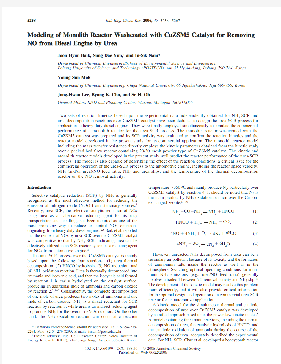
Catalyst Preparation.The CuZSM5catalyst was prepared by wet ion-exchange method using 0.01M of copper acetate solution at room temperature,as extensively described else-where.14The ZSM5type zeolite catalyst with Si/Al molar ratio of 14was obtained from Tosoh Co.(HSZ-830NHA).The monolith reactors were prepared by washcoating CuZSM5catalyst slurry with an alumina binder (NYACOL AL20DW)on the 200CPSI cordierite monolith (Dongsu Industrial Co.).The catalyst powder was completely suspended in the solution when mixed with water and binder during the course of the washcoating procedure,and the mean particle size of the powder including catalyst and alumina binder for washcoating has been confirmed as 2.8μm by particle size analyzer (Beckman Coulter LS 230).The thickness of the washcoats on the honeycomb reactor was measured by a scanning electron microscope (SEM)image (Hitachi,S2460N)shown in Figure 1,and the catalyst powder deposited on the cordierite surface seems to be reason-ably uniform throughout the channels of the monolith
reactor.
Figure 1.Catalytic thickness of the monolith reactor washcoated with CuZSM5catalyst by a SEM
image.
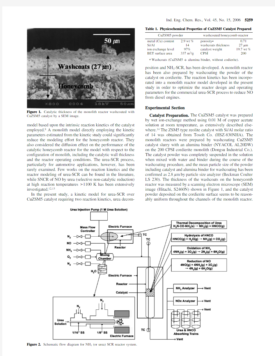
Figure 2.Schematic flow diagram for NH 3(or urea)SCR reactor system.
Table 1.Physicochemical Properties of CuZSM5Catalyst Prepared
CuZSM5powder
washcoated honeycomb reactor metal (Cu)content 2.9wt %porosity a
0.71Si/Al
14washcoats thickness 27μm ion exchange level 97%catalyst weight 19.7wt %BET surface area
337m 2/g
CPSI
200
a
Washcoats (CuZSM5+alumina binder,without codierite).
Ind.Eng.Chem.Res.,Vol.45,No.15,20065259
Listed in Table1are the physicochemical properties of the catalyst and the monolith washcoated with the catalyst prepared. The catalysts were dried at110°C for12h and calcined in air at500°C for5h before and after washcoating.They were again pretreated in air at500°C for1h prior to each experiment. Reaction System and Experimental Procedure.For an intrinsic kinetic study of NH3-SCR,the NO removal activity of the CuZSM5catalyst has been evaluated in a packed-bed flow reactor system with1g of20/30mesh size catalyst,where the effect of mass transfer and pressure drop may be ignored, as shown in Figure2.15A washcoated monolith reactor with 25mm×25mm×25mm dimensions was prepared for the evaluation of the reactor performance,and the reactor space velocity was defined as the ratio of the total volumetric flow rate to the volume of the monolith reactor.A feed gas mixture containing NO(500ppm),NH3(500ppm),O2(5%),H2O (10%),and N2(balance)was supplied through mass flow controllers(Brooks5850E).The kinetic data from a packed-bed reactor were collected over a wide range of reaction temperatures(150-500°C)and reactor space velocities(50000-400000h-1).
For the simultaneous study of urea decomposition and urea-SCR reactions,an additional reactor system for urea decomposi-tion has been fabricated.The reactor consists of a urea injection part,a reactor for urea thermal decomposition,a catalytic reactor, and an analysis train for remaining NH3,urea,and HNCO.4,5 The temperature of the thermal decomposition reactor can be controlled independently.It should be noted that aluminum and SUS316for packed-bed and honeycomb reactors,respectively, have been specifically employed as the reactor materials to prevent the catalytic effects of the reactor.
The concentrations of NO and NH3were analyzed by an on-line chemiluminescent NO-NO x analyzer(Thermo Electron Co.,model42H)and NDIR-type NH3analyzer(Rosemount Analytical,model880A),respectively.To analyze the urea remaining unconverted and the HNCO produced by the decom-position reaction and urea-SCR,a part of the reacted gas was absorbed into a series of the absorption bottles containing deionized water.The concentrations of urea and HNCO absorbed into the water were then analyzed by high-performance liquid chromatography(HPLC)with a UV detector(Younglin UV730D),as reported previously.5,16
Development of Reaction Kinetics and Monolith Reactor Model
SCR by Ammonia.Since NO selectively reacts with NH3 for the urea-SCR process by reaction3,the reaction kinetics of SCR of NO by NH3has been examined.Two primary reactions, NO reduction reaction3and NH3oxidation reaction4,are assumed to mainly occur during the SCR process over CuZSM5 catalyst.10A maximum NO conversion was generally observed as the reaction temperature was varied over the range200-500°C for the present catalytic system because of the ammonia oxidation reaction.8Hence,the intrinsic reaction kinetics for the SCR process has been derived on the basis of reactions3 and4to particularly describe the maximum NO conversion and NH3slip.
In the present study,a dual-site catalysis Langmuir-Hin-shelwood-Hougen-Watson(LHHW)mechanism,where the reaction occurs between adsorbed NO and NH3molecules on two distinct reaction sites such as NH3adsorption site(acidic site)and NO site(basic site),is assumed by the results of the temperature-programmed desorption(TPD)experiments and the previous study on the identical reaction system over CuHM catalyst.17The reaction rate equations can be derived on the basis of Hougen-Watson formalism assuming the surface reaction is the rate-determining step.
Rearranging in terms of conversions of NO and NH3,
where K NO and K NH
3
are the adsorption equilibrium constants and k NO and k NH
3
are the surface reaction rate constants.Since the kinetic model developed is represented by two mass balances expressed by nonlinear coupled first-order ordinary differential equations with respect to NO and NH3,both NO removal activity and NH3slip can be predicted as a function of reactor space velocity and reaction temperature.
Urea Decomposition.Assuming plug flow,the steady-state mass balances for urea and isocyanic acid over a fixed-bed reactor can be expressed as
Equations9and10were derived under the assumption that they are elementary reactions and obey first-order reaction kinetics. Details for the kinetic study of urea decomposition were extensively described in the previous study.5
SCR by Urea.For predicting the performance of the urea-SCR process over the CuZSM5catalyst,the reaction kinetics of NH3-SCR and urea decomposition as derived above have been simultaneously combined.
As the reaction kinetics for urea thermal decomposition by reaction1,HNCO hydrolysis by reaction2,and NO reduction by reaction3,eqs5,9,and10,respectively,have been employed.On the other hand,the mass balance equation for NH3oxidation by reaction4based upon the formation and the consumption of NH3from the decomposition of urea and the reduction of NO,respectively,has been rewritten:
-
d C
NO
dτ
)
k
1
C
NO
C
NH3
(1+K
NO
C
NO
)(1+K
NH3
C
NH3
)
(k
1
)k
NO
K
NO
K
NH3
C
O2
)(5) -
d C
NH3
dτ
)
k
1
C
NO
C
NH3
(1+K
NO
C
NO
)(1+K
NH3
C
NH3
)
+
k
2
C
NH3
(1+K
NH3
C
NH3
)
(k
2
)k
NH3
K
NH3
C
O2
)(6)
d X
NO
dτ
)
k
1
C
NH3
0(1-X
NO
)(1-X
NH3
)
[1+K
NO
C
NO
0(1-X
NO
)][1+K
NH3
C
NH3
0(1-X
NH3
)]
(7)
d X
NH3
dτ
)
k
1
C
NO
0(1-X
NO
)(1-X
NH3
)
[1+K
NO
C
NO
0(1-X
NO
)][1+K
NH3
C
NH3
0(1-X
NH3
)}
+
k
2
(1-X
NH3
)
1+K
NH3
C
NH3
0(1-X
NH3
)
(8)
d C
Urea
dτ
)-k
3
C
Urea
(9)
d C
HNCO
dτ
)k
3
C
Urea
-k
4
C
HNCO
C
H2O
(10)
5260Ind.Eng.Chem.Res.,Vol.45,No.15,2006
It should be noted that the homogeneous noncatalytic oxidation of NH 3during the thermal decomposition of urea was ignored because of the negligible oxidation reaction activity based upon a nitrogen balance in the down stream of the reactor,as reported previously.5
These equations can be rearranged in terms of conversions as follows,
where k 4C H 2O can be treated as a constant (k 4′)because of the relatively high feed concentration of H 2O,10%both in the present study and in an actual exhaust stream from a diesel engine.
Monolith Reactor Model.A mathematical model for the washcoated honeycomb reactor has been developed on the basis of the kinetic study examined over a packed-bed flow reactor for a urea-SCR system.The effect of the external and internal diffusion on NO removal activity in a washcoated monolith reactor has been also considered and included for developing the model similar to the work by Chae et al.8
A material balance of the gas-phase reactants in a channel is
with the initial conditions C i b )C i b,0at x )0.At any axial position x along the channel of the monolith,a material balance over the catalyst layer of thickness d y yields the following:
Equation 16describes the diffusion-reaction interaction for reactants within the pore of washcoats and catalyst.Note that
the axial diffusion term,d 2C i /d x 2,has been ignored in eq 16;when the spatial variables are transformed into a dimensionless group,its coefficient (~10-7)is found to be negligible compared to that for the transverse diffusion term (~1)in eq 16.18The boundary conditions for eq 16are
A material balance at axial position x of the honeycomb reactor over the external gas film yields
The external mass-transfer coefficient k m can be estimated by the Hawthorn correlation,eq 17,which can well describe the developing laminar flow in rectangular channels.18-20
where B is a shape factor of the channel of the honeycomb.Numerical Method.To estimate the kinetic parameters of the global reaction kinetics derived in the present study,the catalytic activity of CuZSM5has been examined over wide ranges of reactor space velocities and reaction temperatures.Upon the basis of the kinetic data,the parameters of the proposed global reaction kinetic expressions,eqs 5and 6,were estimated by fitting the model predictions of NO and NH 3conversions to the experimental data at each temperature of interest.Two nonlinear ordinary differential equations,eqs 7and 8,were solved by Gear’s method,which can handle any degree of the stiffness of the gradients for the model equations while allowing the desired accuracy of integration with moderate computing time.The parameter estimation was made by nonlinear regression,minimizing the sum of squares calculated by eq 19from the experimental and calculated NO and NH 3conversions.A regression routine for the minimization uses the Marquardt algorithm.21
The computer subroutine program for the estimation of the parameters was prepared by using MATLAB (version 6.1,The MathWorks,Inc.).
A mathematical description of the honeycomb reactor derived from the present study is coupled by ordinary differential equations:eq 15with initial values and by partial differential equations and eq 16with nonlinear boundary conditions.The ordinary differential equations have been solved by the Runge -Kutta method.The nonlinear second-order derivatives were discretized by the finite difference method (FDM)and/or accelerated fixed-point iteration (FPI).Results
SCR by Urea.The deNO x performance of the powder form of CuZSM5catalyst (20/30mesh)by urea-SCR over the fixed-bed reactor can be observed in Figure 3.When the temperature of the thermal decomposition reactor was set at 350°C where urea was completely decomposed into NH 3and HNCO,5the
-
d C NH 3d τ
)
k 1C NO C NH 3
(1+K NO C NO )(1+K NH 3C NH 3)
+
k 2C NH 3
(1+K NH 3C NH 3)
-k 3C Urea -k 4C NHCO C H 2O (11)
d X Urea
d τ
)k 3(1-X Urea )(12)
d X HNCO d τ)-k 3C Urea 0(1-X Urea )
C HNCO
0+k 4C H 2O (1-X HNCO )(13)d X NO
d τ)k 1C NH 3
(1-X NO )(1-X NH 3)[1+K NO C NO 0(1-X NO )][1+K NH 3C NH 30(1-X NH 3)]
(7)d X NH 3d τ
)
k 1C NO 0(1-X NO )(1-X NH 3)
[1+K NO C NO 0(1-X NO )][1+K NH 3C NH 30
(1-X NH 3)]
+
k 2(1-X NH 3)
1+K NH 3C NH 3
(1-X NH 3)-
k 3C Urea 0(1-X Urea )
C NH
3
-
k 4C H 2O C NHCO (1-X HNCO )
C NH
3
0(14)
-u d C i b
d x
)k m,i A e (C i b -C i s )(15)
D e,i
d 2C i d y 2
)-r i
(16)
d C i
d y
)0at y )0C i )C i s at y )R
k m,i (C i b -C i s ))D e,i
(d C i d y
)
s
(17)
Sh )B (1+0.095d L Pe
)
0.45
(18)
Minimize
∑i )0
n
(X i exp -X i cal )2(19)
Ind.Eng.Chem.Res.,Vol.45,No.15,20065261
NO removal activity over CuZSM5catalyst by urea-SCR was close to the activity observed by NH 3-SCR.This clearly indicates that HNCO produced in the thermal decomposition reactor successfully further reacts with H 2O to produce NH 3in
the catalytic reactor,thereby making urea as effective as NH 3for NO reduction,when the temperature of the thermal decomposition reactor is >350°C.Again,the hydrolysis reaction is a fast reaction.5It should be noted that the thermal decomposition of urea and the hydrolysis of HNCO simulta-neously occur in the SCR reactor containing CuZSM5catalyst.However,when the temperature of the thermal urea decom-position reactor is 150°C,where urea is not completely decomposed,the catalyst exhibits relatively low NO x conver-sion,particularly at reaction temperatures <250°C,apparently due to the incomplete decomposition of urea resulting in the deficiency of NH 3during the course of the SCR reaction.Thus,the temperature of the thermal urea decomposition reactor is of critical importance for the high performance of the urea-SCR system.Note that the contribution of the residence time to the decomposition of urea should not be excluded.4,5
Reaction Kinetics.Figure 4compares the conversions of NO and NH 3predicted by the kinetic model developed in the present study,eqs 5,9,and 10,with the experimental data from the packed-bed flow reactor at various reactor space velocities.The model well predicts the NH 3-SCR performance over the powder type of the CuZSM5catalyst throughout the reactor operating conditions covered in the present study.Also,a maximum in the NO conversion versus temperature plots can be predicted by the model.The kinetic parameters estimated by the
numerical
Figure 3.Effect of the temperature of the thermal urea-decomposition reactor for NO reduction by urea over CuZSM5catalyst;SV )100000h -1
.
Figure https://www.360docs.net/doc/8e11035448.html,parisons of predicted and measured NO and NH 3conversions over CuZSM5catalyst for four different reactor space velocities.
5262Ind.Eng.Chem.Res.,Vol.45,No.15,2006
method based upon the experimental data are listed in Table 2.The results have been reconfirmed by Arrhenius temperature dependence,revealing the good linearity of the constants with respect to the temperatures.It should be noted that the temperature dependences of the rate constants for the thermal decomposition of urea and hydrolysis of HNCO were well described by Yim et al.5As listed in Table 2,the activation energy of NH 3oxidation,39.7kcal/mol,is nearly 3times greater than that of NO reduction,12.5kcal/mol.This is a primary cause for observing a maximum in the NO conversion as a function of temperature as shown in Figure 4.
Figure 5shows the prediction of NO and NH 3conversions by the model to describe the experimental data attained at a variety of NH 3/NO feed ratios (0.7,0.85,and 1.0)for a 2-fold check of the validity of the reaction kinetics developed in the present study.The level of the maximum NO conversion strongly depends on the NH 3/NO feed ratio,and the model well predicts the NO conversion and NH 3slip of the catalyst with respect to the NH 3/NO feed ratio and reaction temperature.The present kinetic model is quite adequate in predicting the NO conversion and NH 3slip of the CuZSM5catalytic system at various reaction conditions including the reactor space velocity,NH 3/NO feed ratio,and reaction temperature.
For the urea decomposition reaction,the kinetic parameters were obtained by the previous study as listed in Table 2.5Yim et al.reported that the activation energy for the thermal decomposition of urea in the catalytic reactor,5.4kcal/mol,is quite close to the value observed for the thermal decomposition reactor (5.5kcal/mol).5On the other hand,the CuZSM5catalyst employed in the present study significantly reduced the activa-tion energy for the HNCO hydrolysis reaction from 14.9to 3.8kcal/mol.
Modeling of Washcoated Monolith Reactor.The honey-comb reactor model developed in the present study s eqs 15-
17along with eqs 5,9,and 10s has been employed to predict the deNO x performance by NH 3of the monolith reactor washcoated with the CuZSM5catalyst at three different reactor space velocities,as shown in Figure 6.
The present monolith model with the kinetic parameters directly estimated from the packed-bed flow reactor containing the catalyst powders adequately describes the effects of the reactor space velocity on the NO removal activity and NH 3slip over the washcoated honeycomb reactor.It also reveals that the present model considering both external and internal diffusion can describe the geometric effects of a monolith,such as the thickness of washcoats of the honeycomb reactor measured by SEM image as shown in Figure 1.
Figure 7also compares the predicted and measured NO and NH 3conversions over CuZSM5catalyst washcoated on a honeycomb reactor at various NH 3/NO feed ratios (0.7,0.85,and 1.0).These results reveal that the level of the maximum NO conversion strongly depends on the NH 3/NO feed ratio,and the model well predicts the NO conversion and NH 3slip of the catalyst as function of NH 3/NO feed ratio and the reaction temperatures.Discussion
Modeling of Urea-SCR Technology over the Powder Type of CuZSM5Catalyst.Numerical simulation of the urea-SCR performance over 20/30mesh size of CuZSM5catalyst was performed by combining the reaction kinetics for both urea decomposition and NH 3-SCR,as mentioned.Figure 8shows the model prediction of NO removal activity by urea with respect to the temperature of the thermal decomposition reactor.Both kinetic models independently developed in the present study well predict the reactor performance of the urea-SCR process,as shown in Figure 8.It also compares the
predicted
Figure https://www.360docs.net/doc/8e11035448.html,parisons of predicted and measured NO and NH 3conversions over CuZSM5catalyst for two different NH 3/NO ratios (i.e.,0.7and 0.85);SV )100000h -1.
Table 2.Kinetic Parameters Estimated from the Experimental Data Observed over Packed-Bed Reactor
SCR by NH 3
k 1)3.09×10¹⁶exp(-12457/RT )k 2)6.56×10¹⁵exp(-39712/RT )K NO )4.13×10⁻⁵exp(14969/RT )K NH 3)1.39×10⁻²exp(21541/RT )
thermal decomposition reactor a
catalytic reactor a
urea decomposition 5
k 3)4.9×10³exp(-5505/RT )k 3)4.5×10³exp(-5405/RT )k 4′)2.5×10⁵exp(-15861/RT )
k 4′)3.2×10⁴exp(-3780/RT )
a
k 4′)k 4C H 2O .
Ind.Eng.Chem.Res.,Vol.45,No.15,20065263
and measured NO,NH 3,urea,and HNCO conversions at the temperature of thermal decomposition reactor of 350°C,where urea can be completely decomposed into two moles of NH 3and one mole of CO 2,as confirmed in Figure 3.The model well predicts the experimental data and reveals that the HNCO generated in the thermal decomposition reactor has been immediately hydrolyzed in the catalytic reactor,and then the produced NH 3can remove NO.Again,in the catalytic reactor,NH 3produced by both thermal decomposition and catalytic hydrolysis of HNCO can immediately react with NO on the surface of the catalyst.The model is also capable of describing a maximum NO conversion with increasing temperature,which is typical for SCR reaction as well as NH 3slip.
The model developed in the present study can also
describe
Figure https://www.360docs.net/doc/8e11035448.html,parisons of predicted and measured NO and NH 3conversions over the monolith reactor washcoated by CuZSM5catalyst for three different reactor space
velocities.
Figure https://www.360docs.net/doc/8e11035448.html,parisons of predicted and measured NO and NH 3conversions over the monolith reactor washcoated by CuZSM5catalyst for two different NH 3/NO ratios (i.e.,0.7and 0.85);SV )10000h -1.
5264Ind.Eng.Chem.Res.,Vol.45,No.15,2006
the effect of the thermal decomposition reactor temperature on the NO removal activity,as shown in Figure https://www.360docs.net/doc/8e11035448.html,pared with the result in Figure 8a,the conversion of NO is rather low,especially at a reaction temperature <300°C when the tem-perature of thermal decomposition reactor is 150°C.It is quite understandable that the deNO x performance of urea-SCR is strongly influenced by the temperature of the thermal decom-position reactor,as mentioned before.When the urea is completely decomposed into ammonia and isocyanic acid,NO removal activity by urea corresponds to that by ammonia.Therefore,the kinetic parameters estimated for the model developed in the present study were quite appropriate to describe the performance of the urea-SCR process over CuZSM5catalyst.In addition,no direct reaction of NO with urea may be expected in the present work.
Modeling of Urea-SCR Technology over Monolith Reac-tor.The honeycomb reactor model developed in the present study s eqs 15and 16along with the reaction kinetics,eqs 7,12,13,and 14s has been employed to predict the deNO x performance of the honeycomb reactor washcoated with the CuZSM5catalyst by urea-SCR,as shown in Figure 9.Under the operating conditions of Figure 9a,by the calculation via eqs 9and 10,250ppm of the feed concentration of urea into the urea thermal rector will produce 199ppm NH 3and 189ppm HNCO,as well as 56ppm of unreacted urea in the thermal decomposition reactor.Although urea did not decompose completely in the thermal reactor,the NO removal activity over the honeycomb reactor has revealed similar activity trends to that over the packed-bed reactor with the powder type of the catalyst,as described.This result simply indicates that a small amount of unreacted urea cannot affect the NO removal activity,even at low reaction temperature.The remaining urea can be also decomposed as the temperature of the catalytic reactor is increased,which leads the further reaction of NO,as shown in Figure 9a.
Figure 9b shows the result of model prediction when
the
Figure https://www.360docs.net/doc/8e11035448.html,parison of predicted and measured conversions over the CuZSM5catalyst;SV )100000h -1.Conditions of thermal decomposition reactor:1.6L/min (a)at 350°C [feed composition to SCR reactor;urea (0ppm),HNCO (216ppm),NH 3(284ppm)],(b)at 150°C [feed composition to SCR reactor;urea (143ppm),HNCO (107ppm),NH 3(107
ppm)].
Figure https://www.360docs.net/doc/8e11035448.html,parison of predicted and measured conversions over the monolith reactor washcoated by CuZSM5catalyst;SV )10000h -1.Conditions of thermal decomposition reactor: 3.3L/min (a)at 350°C [feed composition to SCR reactor;urea (56ppm),HNCO (189ppm),NH 3(199ppm)],(b)at 150°C [feed composition to SCR reactor;urea (191ppm),HNCO (59ppm),NH 3(59ppm)].
Ind.Eng.Chem.Res.,Vol.45,No.15,20065265
temperature of thermal decomposition was set at 150°C.The model well describes the experimental data with respect to the operating condition of the thermal decomposition reactor for urea.As expected,the deNO x performance of urea-SCR process has been strongly influenced by the amount of urea decomposed in the thermal and catalytic rectors particularly at low reaction temperature.Figure 10also shows that the effect of the urea/NO feed ratio on the NO removal activity is similar to that for the NH 3-SCR process in Figure 7,as mentioned.Obviously,the model is superbly capable of describing the deNO x performance of the urea-SCR process as well as NH 3and urea slips over the monolith reactor washcoated with CuZSM5catalyst in the wide range of operating condition of urea-SCR technology for removing NO from automotive diesel engines.It should be noted that a transient analysis of the kinetic and reactor models developed has to be considered for the practical mobile application of the urea-SCR technology.Conclusions
The removal of NO x by urea-SCR strongly depends on the operating conditions of the reactor,especially the temperature and the residence time of the feed gas stream in the thermal decomposition reactor.A model based on four main reactions,including thermal decomposition of urea,the catalytic hydrolysis of HNCO,reduction of NO,and NH 3oxidation,well describes the experimental data with appropriate activation and adsorption energies over a wide range of experimental conditions.Since the parameters estimated from the kinetic study over a catalyst pellet have been directly employed to anticipate the performance of the monolith reactor washcoated by CuZSM5catalyst,the present approach will save much effort and time for estimating and predicting the deNO x activity of the monolith for the commercial design of the honeycomb reactor for removing NO from a diesel engine by urea.Furthermore,the performance of the monolith reactor washcoated with any other catalyst can be predicted even without the fabrication of the reactor,if there is available reaction kinetics confirmed by the experimental data over the powder type of its counterpart catalyst.Again,the model for urea-SCR developed in the present study can predict the reactor performance of the washcoated monolith reactor
commonly employed for automotive engines and may provide a practical guideline for the design of a commercial urea-SCR process.Nomenclature
A e )honeycomb geometry surface area,cm 2/cm 3
B )shape factor of the channel of a honeycomb (2.976for a square)
C i )concentration of i species,mol/cm 3d )width of honeycomb channel,cm
d h )hydraulic diameter of honeycomb channel,cm D )diffusivity,cm 2/s
D e,i )effective diffusivity of the i th species,cm 2/s
k m,i )gas -solid mass-transfer coefficient of the i th species,cm/s
L )reactor length,cm
r i )reaction rate for the i th species based on catalytic volume,mol/(cm 3?s)
R )washcoat thickness for a washcoated honeycomb,cm u )average velocity at the reactor inlet,cm/s
x )axial coordinate in the honeycomb channel geometry,cm y )transverse coordinate in the honeycomb channel geometry,cm
τ)reactor space time (residence time)of the feed gas stream,s Subscripts and Superscripts b,s )bulk and surface,respectively Dimensionless Groups
Pe )Peclet number,ud h /D
Sh )Sherwood number,k m d h /D Literature Cited
(1)Bosch,H.;Janssen,F.Catalytic Reduction of Nitrogen Oxides:A Review on the Fundamentals and Technology.Catal.Today 1988,2,369-532.
(2)Koebel,M.;Elsener,M.;Kleemann,M.Urea-SCR:A Promising Technique to Reduce NO x Emissions from Automotive Diesel Engines.Catal.Today 2000,59,335-
345.
Figure https://www.360docs.net/doc/8e11035448.html,parison of predicted and measured conversions over the monolith reactor washcoated by CuZSM5catalyst at two urea/NO feed ratios;SV )10000h -1.Conditions of thermal decomposition reactor:350°C (a)(urea ×2)/NO )0.75[feed composition to SCR reactor;urea (27ppm),HNCO (92ppm),NH 3(97ppm)],(b)(urea ×2)/NO )0.85[feed composition to SCR reactor;urea (42ppm),HNCO (142ppm),NH 3(149ppm)].
5266Ind.Eng.Chem.Res.,Vol.45,No.15,2006
(3)Miller,W.R.;Klein,J.T.;Mueller,R.;Doelling,W.;Zuerbig,J. The De V elopment of Urea-SCR Technology for US Hea V y Duty Trucks; SAE Technical Paper No.2000-01-0190;SAE International:Warrendale, PA,2000.
(4)Baik,J.H.;Yim,S.D.;Nam,I.-S.;Mok,Y.S.;Lee,J.-H.;Cho,B. K.;Oh,S.H.Control of NO x emissions from diesel engine by selective catalytic reduction(SCR)with urea.Top.Catal.2004,30/31,37-41.
(5)Yim,S.D.;Kim,S.J.;Baik,J.H.;Nam,I.-S.;Mok,Y.S.;Lee, J.-H.;Cho,B.K.;Oh,S.H.Decomposition of Urea into NH3for the SCR Process.Ind.Eng.Chem.Res.2004,43,4856-4863.
(6)Lu¨ders,H.;Backes,R.;Hu¨thwohl,G.;Ketcher,D.A.;Horrocks,R. W.;Hurley,R.G.;Hammerle,R.H.An Urea Lean NOx Catalyst System for Light Duty Diesel Vehicles;SAE Technical Paper No.952493;SAE International:Warrendale,PA,1995.
(7)Koebel,M.;Strutz,E.O.Thermal and Hydrolytic Decomposition of Urea for Automotive Selective Catalytic Reduction Systems:Thermo-chemical and Practical Aspects.Ind.Eng.Chem.Res.2003,42,2093-2100.
(8)Chae,H.J.;Choo,S.T.;Choi,H.;Nam,I.-S.;Yang,H.S.;Song, S.L.Direct Use of Kinetic Parameters for Modeling and Simulation of a Selective Catalytic Reduction Process.Ind.Eng.Chem.Res.2000,39, 1159-1170.
(9)Long,R.Q.;Yang,R.T.Superior ion-exchanged ZSM-5Catalyst for Selective Catalytic Oxidation of Ammonia to https://www.360docs.net/doc/8e11035448.html,mun. 2000,1651-1652.
(10)Komatsu,T.;Nunokawa,M.;Moon,I.S.;Takahara,T.;Namba, S.;Yashima,T.Kinetic Studies of Reduction of Nitric Oxide with Ammonia on Cu2+-exchanged Zeolites.J.Catal.1994,148,427-437.
(11)Boer,F.P.;Hegedus,L.L.;Gouker,T.R.;Zak,K.P.Controlling Power Plant NO x Emissions:Catalytic Technology,Economics,and Prospects.CHEMTECH1990,20,312-319.
(12)Rota,R.;Antos,D.;Zanoelo,E?.F.;Morbidelli,M.Experimental and Modeling Analysis of the NO x OUT Process.Chem.Eng.Sci.2002, 57,27-38.
(13)Alzueta,M.U.;Bilbao,R.;Millera,A.;Oliva,M.;Iban?ez,J.C. Interactions between Nitric Oxide and Urea under Flow Reactor Conditions. Energy Fuels1998,12,1001-1007.
(14)Ganemi,B.;Bjo¨rnbom,E.;Paul,J.Conversion and in situ FTIR Studies of Direct NO Decomposition over Cu-ZSM5.Appl.Catal.,B1998, 17,293-311.
(15)Baik,J.H.;Yim,S.D.;Nam,I.-S.;Lee,J.-H.;Cho,B.K.;Oh,S.
H.Selective Catalytic Reduction of Diesel Engine NO x Emissions with NH3/Urea.In Book of Abstract for18th North American Catalysis Society Meeting,North American Catalysis Society:Cancun,Mexico,2003;p89.
(16)Kleemann,K.;Elsener,M.;Koebel,M.;Wokaun,A.Hydrolysis of Isocyanic Acid on SCR Catalysts.Ind.Eng.Chem.Res.2000,39,4120-4126.
(17)Choi,E.Y.;Nam,I.-S.;Kim,Y.G.TPD Study of Mordenite-Type Zeolite for Selective Catalytic Reduction of NO by NH3.J.Catal. 1996,161,597-604.
(18)Choi,H.;Ham,S.-W.;Nam I.-S.;Kim,Y.G.Honeycomb Reactor Washcoated with Mordenite Type Zeolite Catalysts for the Reduction of NO x by NH3.Ind.Eng.Chem.Res.1996,35,106-112.
(19)Hawthorn,R.D.Afterburner Catalysts Effects of Heat and Mass Transfer between Gas and Catalyst Surface:Recent Advances in Air Pollution Control.AIChE Symp.Ser.1974,70,428-438.
(20)Beeckman,J.W.;Hegedus,L.L.Design of Monolith Catalysts for Power Plant NO x Emission Control.Ind.Eng.Chem.Res.1991,30, 969-978.
(21)Marquardt,D.W.An Algorithm for Least-Squares Estimation of Nonlinear Parameters.J.Soc.Ind.Appl.Math.1963,11,431-441.
Recei V ed for re V iew February17,2006
Re V ised manuscript recei V ed May1,2006
Accepted May11,2006
IE060199+ Ind.Eng.Chem.Res.,Vol.45,No.15,20065267
短路电流计算公式
变压器短路容量-短路电流计算公式-短路冲击电流的计算发布者:admin 发布时间:2009-3-23 阅读:513次供电网络中发生短路时,很大的短路电流会使电器设备过热或受电动力作用而遭到损坏,同时使网络内的电压大大降低,因而破坏了网络内用电设备的正常工作。为了消除或减轻短路的后果,就需要计算短路电流,以正确地选择电器设备、设计继电保护和选用限制短路电流的元件。 二.计算条件 1.假设系统有无限大的容量.用户处短路后,系统母线电压能维持不变.即计算阻抗比系统阻抗要大得多。 具体规定: 对于3~35KV级电网中短路电流的计算,可以认为110KV及以上的系统的容量为无限。只要计算35KV及以下网络元件的阻抗。 2.在计算高压电器中的短路电流时,只需考虑发电机、变压器、电抗器的电抗,而忽略其电阻;对于架空线和电缆,只有当其电阻大于电抗1/3时才需计入电阻,一般也只计电抗而忽略电阻。 3. 短路电流计算公式或计算图表,都以三相短路为计算条件。因为单相短路或二相短路时的短路电流都小于三相短路电流。能够分断三相短路电流的电器,一定能够分断单相短路电流或二相短路电流。 三.简化计算法 即使设定了一些假设条件,要正确计算短路电流还是十分困难,对于一般用户也没有必要。一些设计手册提供了简化计算的图表.省去了计算的麻烦.用起来比较方便.但要是手边一时没有设计手册怎么办?下面介绍一种“口诀式”的计算方法,只要记牢7句口诀,就可掌握短路电流计算方法。 在介绍简化计算法之前必须先了解一些基本概念。 1.主要参数 Sd三相短路容量(MV A)简称短路容量校核开关分断容量 Id三相短路电流周期分量有效值(KA)简称短路电流校核开关分断电流和热稳定 IC三相短路第一周期全电流有效值(KA) 简称冲击电流有效值校核动稳定 ic三相短路第一周期全电流峰值(KA) 简称冲击电流峰值校核动稳定 x电抗(W) 其中系统短路容量Sd和计算点电抗x 是关键. 2.标么值 计算时选定一个基准容量(Sjz)和基准电压(Ujz).将短路计算中各个参数都转化为和该参数的基准量的比值(相对于基准量的比值),称为标么值(这是短路电流计算最特别的地方,目的是要简化计算). (1)基准 基准容量Sjz =100 MV A 基准电压UJZ规定为8级. 230, 115, 37, 10.5, 6.3, 3.15 ,0.4, 0.23 KV 有了以上两项,各级电压的基准电流即可计算出,例: UJZ (KV)3710.56.30.4
铁心电抗器电感计算公式【通用
铁心电抗器电感计算公式 铁心电抗器电感计算公式 当有气隙时,其磁阻主要取决于气隙尺寸。由于气隙的磁化曲线基本上是线性的,所以其电感值仅取决于自身线圈匝数、铁心截面和气隙的尺寸。 主磁通所产生的电感LM LM=ψ/ I =μ0W2 SM / n d=1.257 W2 SM / n d×10 – 8 (H) 式中: ψ─磁通量(Wb) I ─电流(A) μ0 ─空气中的导磁率= 0.4π×10 – 6 = 1.257×10 – 6 (H/m) W ─线圈匝数 SM ─气隙处总有效截面积(cm 2 ) n ─气隙个数 d─单个气隙尺寸(cm ) SM ─气隙处总有效截面积计算 选择单个气隙尺寸d=0.5~3 cm 计算行射宽度E E=d/π ln ((H+d) /d) cm π=PI() 圆周率 H—铁饼高度,一般5 cm
计算行射面积(圆形铁心时)SE SE=2E×(AM+BM+2E) cm 2 AM—叠片总厚度cm BM—最大片宽cm (矩形铁心时)SE SE=2E×(AM+BM) cm 2 AM—叠片总厚度cm BM—片宽cm 计算气隙处总有效截面积 SM=SF / KF +SE cm 2 SF—铁芯截面 KF—叠片系数 漏磁通所产生的电感Ld Ld= 1.257 W2 Sdρ/ H1×10 – 6 (H) 式中: W —线圈匝数 Sd —总漏磁链 ρ—洛氏系数 铁心电抗器电感计算公式 H1 —线圈高度cm Sd=2π/3 F RF +πRn2 - SF / KF ρ=1- 2(RW - RO)/(πH1)
式中: F —线圈幅向尺寸cm RF —线圈平均半径cm Rn —线圈内半径cm RW —线圈外半径cm RO —铁芯半径cm H1 —线圈高度cm 线圈总电感 L= LM + Ld 线圈匝数W计算 ∵ I L = W φ = W B S ∴ W = I L /(B S) 程序计算步骤: 输入:I1,L 1. 计算容量P = I1 ^ 2* L / 1000 2. 参考铁心截面积QC = 15 * P ^ 0.5 3. 参考片宽DOOL =(QC / 1.5)^ 0.5 * 10 4. 参考铁心厚DOOS = DOOL * 1.5 5. 铁心截面积QC = Int(DOOL * DOOS * KQ) / 100 6. 初设磁密BMM =9000 7. 匝数N1 = Int(2 ^ 0.5 *I1 * I1*L * 10 ^ 5 / (BMM * QC))
浅谈:电抗器的分类及特点
本文摘自再生资源回收-变宝网(https://www.360docs.net/doc/8e11035448.html,)浅谈:电抗器的分类及特点 电抗器也叫电感器,一个导体通电时就会在其所占据的一定空间范围产生磁场,所以所有能载流的电导体都有一般意义上的感性。 一、电抗器的分类 按功能、按接法、按结构及冷却介质、按用途进行分类。 1、按功能:分为限流和补偿。 2、按接法:分为并联电抗器和串联电抗器。 3、按结构及冷却介质:分为空心式、铁心式、干式、油浸式等,例如:干式空心电抗器、干式铁心电抗器、油浸铁心电抗器、油浸空心电抗器、夹持式干式空心电抗器、绕包式干式空心电抗器、水泥电抗器等。
4、按用途:按具体用途细分,例如:限流电抗器、滤波电抗器、平波电抗器、功率因数补偿电抗器、串联电抗器、平衡电抗器、接地电抗器、消弧线圈、进线电抗器、出线电抗器、饱和电抗器、自饱和电抗器、可变电抗器(可调电抗器、可控电抗器)、轭流电抗器、串联谐振电抗器、并联谐振电抗器等。 二、电抗器的特点 1、该进线电抗器为三相,均为铁芯干式; 2、外露部件均采取了防腐蚀处理,引出端子采用镀锡铜管端子; 3、进线电抗器芯柱部分紧固件采用无磁性材料,减少运行时的涡流发热现象; 4、该进线电抗器与国内同类产品相比具有体积小、重量轻、外观美等优点,可与国外知名品牌相媲美; 5、线圈采用H级漆包扁铜线绕制,排列紧密且均匀,外表不包绝缘层,且有极佳的美感且有较好的散热性能; 6、铁芯采用优质低损耗进口冷轧硅钢片,气隙采用环氧层压玻璃布板作间隔,以保证电抗器气隙在运行过程中不发生变化; 7、进线电抗器的线圈和铁芯组装成一体后经过预烘→真空浸漆→热烘固化这一工艺流程,采用H级浸渍漆,使电抗器的线圈和铁芯牢固地结合在一起,不但大大减小了运行时的噪音,而且具有极高的耐热等级,可确保电抗器在高温下亦能安全地无噪音地运。 本文摘自变宝网-废金属_废塑料_废纸_废品回收_再生资源B2B交易平台网站; 变宝网官网:https://www.360docs.net/doc/8e11035448.html,/?qx 买卖废品废料,再生料就上变宝网,什么废料都有!
三相滤波电抗器参数计算实例
三相滤波电抗器作 一.设计依据 482V 500V 1,电抗器总额定容量16.66kvar 15.51kvar 2,电抗率 4.16% 4.16% 3,总电感量 0.0577mH 0.0619mH 4,电容器安装总容量550Kvar 550Kvar 5,电容器额定电压 480v 500v 6,电容器基波容量383.31Kvar 357.31Kvar 7,成套装置分四组即:50kvar ,100kvar ,200kvar ,200kvar 。 按安装容量分配: 1/2/4/4 故需制做四只三相或12只单相电抗器 二,电抗器制作要求 ⒈ 电抗器的绝缘等级660v 。 ⒉ 电抗器的耐热等级H 级。 ⒊ 电抗器的额定容量S ,0.7Kvar 。 ⒋ 电抗器的电抗率 4.16%。 ⒌ 电抗器的电感1.995mH 。 ⒍ 电抗器的额定电流33.2A 。 ⒎ 电抗器的绝缘耐压5千伏。 三,铁芯计算及材料的选择 ⒈ 硅钢片选用D310取向硅钢片。 2.电抗器容量的确定。 (1)给定无功16.6Kvar 求电容量 C =92102?fU ?=9210500 3146.16??=910785000006.16?=211.46μF (2)根具电容量求容抗 Xc= 6101c ω=61046 .2113141??=15.064?
(3)已知容抗和电抗率求电抗 XL=0.0416064.15?=0.6266624 ? (4)求制作电抗器的电感 L=310?ωXL =310314 6266624.0=1.9957mH (5)根具电容器的容抗和额定电压求电抗器的流 IL=XC u =064 .15500=33.2A (6)求制作电抗器的容量 Q=310-IV =33.2?21310-=0.7kvar ⒉ 铁芯柱截面积的选择。 ⑴按0.7Kvar 计算铁芯柱的截面积。(按三相变 直径 D =kd 4P =69×47.0=6.31cm (KD-经验数据) 铁芯柱圆截面积 S =π×2231.6??? ??=3.14×9.55=312cm 电抗器的电压 V =P ÷I =0.7÷33.2=21V 一、 硅钢片宽度的选择 1 硅钢片宽度尺寸的计算 E =(2.6-2.9)2LI =2.922.330019957.0?=4.3cm 取4.8 2 铁心厚度尺寸的计算 ⑴ 净厚度B =S ÷E =31 2cm ÷4.8cm =6.5 cm 硅钢片数为:6.5÷0.27=240片 ⑵铁心厚度 s B =B ÷K =6.5 cm ÷0.91=7.15 cm 二、 绕组匝数w 和气隙的计算 ⒈ 绕组匝数的计算w
基于遗传算法的干式空心电抗器优化设计
基于遗传算法的干式空心电抗器优化设计 发表时间:2018-10-22T13:32:46.193Z 来源:《防护工程》2018年第14期作者:倪璐佳1 官云2 [导读] 干式电抗器主要用于补偿电力系统的无功容量。它对于降低系统故障和提高运行质量有着重要的作用 倪璐佳1 官云2 1. 国网浙江省电力有限公司检修分公司浙江台州 318000; 2.国网浙江省电力有限公司台州供电公司浙江台州 318000 摘要:干式电抗器主要用于补偿电力系统的无功容量。它对于降低系统故障和提高运行质量有着重要的作用。本文基于等电阻电压约束,采用改进的自适应遗传算法对空心电抗器进行优化。将该空心电抗器的优化设计方案与原设计方案进行比较,电抗器的成本显著减小,产品性能得到提升,降低了生产成本和运行成本。关键词:干式空心电抗器遗传算法优化设计 1 引言 电抗器是因其电感特性而应用于电力系统中的装置或器件,在电路中起到无功补偿、限流、平波、滤波、阻尼、移相等作用。研究空心电抗器的电磁参数、温升、损耗等对干式空心电抗器的设计,延长其寿命和保障电力系统的安全运行具有重要的意义,这些参数也是优化设计的基础。 2 遗传算法在空心电抗器设计中的应用 干式空心电抗器的设计要综合考虑电感、电流、电流密度、温升和损耗等方面的要求,确定出空心电抗器的结构参数,包括内径、包封数、各包封中的并联层数、各层的匝数以及导线线径等。空心电抗器的优化设计是指在满足规定的性能指标下,以重量最轻为目标,运用合适的优化方法,寻求电抗器产品的最优设计方案。 2.1 设计方法 采用等电阻电压法,将每层导线视作一条支路,则空心电抗器由多条支路并联组成。当空心电抗器的内径、包封数、各包封中的并联层数、各层轴向并联层数、各层径向并联层数和各层导线线径等设计变量确定的情况下,可按照不同的约束条件,求得各层导线得匝数和电流。 假设空心电抗器由n层并联导线构成,可以将每个导线看成是一个线圈,为一条支路。每层线圈的端电压方程为: (2.1) 由式(3.1)可以看出,若,则任意两层线圈的感应电动势相同,所以等电阻电压可以消除环流的影响。 以各层线圈导线中电阻电压相等作为约束条件的设计方法即等电阻电压法,该方法使得整个电抗器的电阻损耗最低。 2.2改进的自适应遗传算法 遗传算法主要由选择、交叉和变异三个基本算子组成。交叉概率Pc和选择概率Pm是影响遗传算法性能的关键。对于交叉概率,Pc 越大,产生新个体的速度越快,但是Pc太大适应度大的个体被破坏的可能性也增大;Pc太小,不易产生新的个体,容易陷入局部最优。对于变异概率,若Pm太大,则遗传算法成了纯粹的随机算法;若Pm太小,则不容易产生新的个体,从而陷入局部最优。因此人们提出了一种自适应遗传算法,其自适应交叉算子和变异算子如下: 式中,表示最大适应度函数值;表示平均适应度函数;表示交叉个体中适应度较大的个体的适应度;f表示变异个体的适应度。由上式可知,当总群适应度比较集中时则增大个体的交叉和变异概率,当种群个体比较分散的则减少个体的交叉和变异概率,可以自适应的调整Pc和Pm的大小。针对遗传算法早熟的问题,对自适应遗传算法的交叉和变异概率加以改进:群体的直径:;个体到平均值点的距离:。然后重点考虑这些点在中间区域的分布情况。
铁芯串联电抗器
高倍不饱合铁芯串联电抗器 工频铁芯串联电抗器用于高低压电容补偿的限流,电动机起动限流,低通滤波等。 传统铁芯串联电抗器由于不饱合电流比较小,对常用的几种电抗器做了实际测试,不饱合电流一般在额定电流的1.1-1.35之间,最大的可达1.8倍。2倍额定电流就全饱合了,饱合后变成了非线性负载并产生大量电流谐波。电容器的串联电抗器主要是限制合闸涌流,因为在合闸时电容电压为0,合闸瞬间由于电容电压不能突变相当于短路,也就是电抗器的瞬时压降等于电源相电压。流过电抗器的电流可能达到额定电流8-10倍,对于传统电抗器合闸瞬间是完全饱合的,相当于一个空心电抗器。所以对合闸涌流限制作用很小。为了解决这个问题,我们研发出来大于8倍不饱合电流的串联电抗器。它可以在合闸时工作在不饱合状态,很好限制了合闸涌流。 一:在正常工作时传统电抗器端电压比较高,所以消耗的无功也比较多。比如电抗器是14%,正常工作时压降是35v,配30kvar电容器(线电压525v),电抗器消耗的无功是2.86kvar。电容器实际端电压=380*(1+14%)=433v,电容器实际发的的无功功率 =27.2A*1.732*433=20.4Kvar。向系统实际补偿无功 =20.4-2.86=17.54kvar,只有电容标称容量58.5%,所以电容利用率很低,并且由于选用14%电抗器使得所选电容器耐压也升高了,
增加电容器成本。 采用高倍不饱合串联工频电抗器,同样容量的电抗器正常运行的端电压2.2v,消耗的无功0.215Kvar。配30kvar电容器(线电压450v),电容器实际端电压=383v,电容器实际发的的无功功率 =33A*1.732*383=21.89Kvar。向系统实际补偿无功=21.67kvar,是电容标称容量72.2%,所以电容利用率高多了,并且由于电抗器的端电压低了,使得所选电容器耐压也低了,减少电容器成本。二:传统电抗器由于饱合电流小,在系统电压比较高的场合,电容电流增大使得电感电流超过饱合电流并大量产生电流谐波,电抗器变成谐波源。同时磁密很大,铁芯噪声温升都增大,严重时电抗器无法工作。 采用高饱合串联工频电抗器,正常工作磁密很小,只有0.18T,铁芯即使在最大谐波电压下无噪音温升很低。 三:如果系统电压畸变也就是电压谐波比较大时,传统电抗器电感值对谐波增加比较多,电容补偿回路对母线呈感性增大。这样就对补偿系统谐波无功的作用降低,也无法降低电压畸变。采用高倍不饱合串联工频电抗器,对主要谐波都呈容性。因此可以补偿系统谐波无功降低系统电压畸变。也就是具有一定的滤波功能。 高倍不饱和串联工频铁芯电抗器适用小于1Khz以下的工频和中 频系统,工作电压110KV及以下各个电压等级。。
干式空心滤波电抗器
干式空心滤波电抗器 技术条件 1. 概述: 本技术条件适用于6kV~66kV电力系统,与电容器连接构成调谐滤波回路,使其在音频范围内谐振,用以滤去谐波的电抗器。滤波电抗器可以串联在系统上也可以并联在系统上。 本技术条件不适用于并联连接用的调谐或滤波电抗器,对于此类电抗器可以参考并联电抗器的技术条件。 干式空心滤波电抗器为单相或由单相组成的三相电抗器。 本技术条件用于干式空心滤波电抗器的定义、型号和分类、技术要求、试验方法、检验规则、产品标志及出厂文件,铭牌的基本内容、包装运输及贮存的基本要求等。 2. 引用标准: 下列标准包含的条文,通过在本技术条件中引用而构成的条文。在编制本技术条件时所有版本均为有效。所有标准都会被修订,使用本技术条件的各方应探讨使用下列标准最新版本的可能性。 GB10229-88 电抗器 GB311.1-1997 高压输变电设备的绝缘配合 GB1094.1-1996 电力变压器第1 部分总则 GB1094.2-1996 电力变压器第2 部分温升 GB1094.3-2003 电力变压器第3 部分绝缘水平、绝缘试验和外绝缘空气间隙 GB1094.5-2003 电力变压器第5 部分承受短路的能力 GB/T1094.10-2003 电力变压器第10 部分声级测定 GB6450-1986 干式电力变压器 GB 10228-1997 干式电力变压器技术参数和要求 GB/T 2900.15-1997 电工术语变压器、、互感器、调压器和电抗器 GB7449-1987 电力变压器和电抗器的雷电冲击和操作冲击试验导则 DL462-1992 高压并联电容器用串联电抗器订货技术条件 JB5346-1998 串联电抗器
各种电抗器的计算公式
各种电抗器的计算公式 加载其电感量按下式计算:线圈公式 阻抗(ohm) = 2 * 3.14159 * F(工作频率) * 电感量(mH),设定需用 360ohm 阻抗,因此:电感量(mH) = 阻抗 (ohm) ÷ (2*3.14159) ÷ F (工作频率) = 360 ÷ (2*3.14159) ÷ 7.06 = 8.116mH 据此可以算出绕线圈数: 圈数 = [电感量* { ( 18*圈直径(吋)) + ( 40 * 圈长(吋))}] ÷圈直径 (吋) 圈数 = [8.116 * {(18*2.047) + (40*3.74)}] ÷ 2.047 = 19 圈 空心电感计算公式 作者:佚名转贴自:本站原创点击数:6684 文章录入: zhaizl 空心电感计算公式:L(mH)=(0.08D.D.N.N)/(3D+9W+10H) D------线圈直径 N------线圈匝数 d-----线径 H----线圈高度 W----线圈宽度 单位分别为毫米和mH。。 空心线圈电感量计算公式: l=(0.01*D*N*N)/(L/D+0.44) 线圈电感量 l单位: 微亨 线圈直径 D单位: cm 线圈匝数 N单位: 匝 线圈长度 L单位: cm 频率电感电容计算公式: l=25330.3/[(f0*f0)*c] 工作频率: f0 单位:MHZ 本题f0=125KHZ=0.125 谐振电容: c 单位 F 本题建义c=500...1000pf 可自行先决定,或由Q值决定 谐振电感: l 单位: 微亨 线圈电感的计算公式 1。针对环行CORE,有以下公式可利用: (IRON) L=N2.AL L= 电感值(H) H-DC=0.4πNI / l N= 线圈匝数(圈) AL= 感应系数 H-DC=直流磁化力 I= 通过电流(A) l= 磁路长度(cm) l及AL值大小,可参照Micrometal对照表。例如: 以T50-52材,线圈5圈半,其L值为T50-52(表示OD为0.5英吋),经查表其AL值约为33nH L=33.(5.5)2=998.25nH≒1μH 当流过10A电流时,其L值变化可由l=3.74(查表) H-DC=0.4πNI / l = 0.4×3.14×5.5×10 / 3.74 = 18.47 (查表后) 即可了解L值下降程度(μi%) 2。介绍一个经验公式 L=(k*μ0*μs*N2*S)/l
电抗器基本知识介绍
电抗器基本知识介绍 一、干式电抗器的种类与用途 电抗器是重要的的电力设备,在电力系统中起补偿杂散容性电流、限制合闸涌流、限制短路电流、滤波、平波、启动、防雷、阻波等作用。根据电抗器的结构型式可分为空心电抗器、铁心电抗器与半心电抗器。 补偿杂散容性电流的电抗器主要有并联电抗器与消弧线圈。并联电抗器的作用是限制电力传输系统的工频电压升高现象,工频电压升高的原因在于空载长线的电容效应、不对称对地短路故障与突然甩负荷。消弧线圈通常应用在配电系统,它的作用是使得单相对地短路电流不能持续燃烧,导致电弧熄灭。消弧线圈通常具有调谐功能,可根据电力系统的杂散电容与脱谐度改变其电感值。 串联电抗器或称阻尼电抗器的作用是限制合闸涌流。串联电抗器与电力电容器串联使用,用于限制对电容器组合闸时的浪涌电流,通常选取电容器组容量的6%。 限流电抗器是串联于电力系统之中,多用于发电机出线端或配电系统的出线端,起限制短路电流的作用。为了与其他电力设备配合,其实际阻抗不能小于额定值。 滤波电抗器与电容器配合使用,构成LC谐振支路。针对特定次数的谐波达到谐振,滤除电力系统中的有害次谐波。 平波电抗器应用在直流系统中,起限制直流电流的脉动幅值作用。在设计平波电抗器时须注意线圈中的电流是按电阻分布的,设计时最好采用微分方程组计算。若按交流阻抗设计可能造成线圈出现过热现象,且阻抗值未必准确。 启动电抗器用于交流电动机启动时刻,限制 防雷线圈通常用于变电站进出线上,减 阻波器与防雷线圈的应用场合相仿,线 用于阻碍电力 便于将通讯载波提
取出来,实现电力载波的重要设备。 户外空心干式电抗器是20世纪80年代出现的新一代电抗器产品,如图1.1所示。它是利用环氧绕包技术将绕组完全密封,导线相互粘接大大的增加了绕组的机械强度。同时利用新的耐候材料喷吐于包封的表面,使得产品能够满足在户外的苛刻条件下运行。包封间由撑条形成气道,包封间与包封内绕组多采用并联连接以便满足容量与散热的要求。为了满足各个并联支路电流合理分配的需要,采用分数匝来减少支路间的环流问题。为了能够形成分数匝,采用星形架作为绕组的出线连接端。绕组的上下星架通过拉纱方式固定,固化后整个产品成为一个整体。这种结构的电抗器与传统方式的电抗器相比较具有可以直接用于户外、电感为线性、噪音小、防爆、使用维护方便等特点,因而对于某些此产品有可能正逐步取代其他形式的电抗器。 由于受到绕组结构的限制,户外空芯干式电抗器通常不适合电感量(>700mH )较大或电感较小(<0.08mH)但电流较大的场合,否则就会造成体积过于庞大或者支路电流极不平衡。在这两种极端条件下,需要适当改变线圈的绕线形式。此外,空心电抗器通常占地面积最大、对外漏磁最严重,这是这类电抗器的主要缺点。 干式铁心电抗器主要是由铁心和线圈组成的,如图1.2所示。干式铁心电抗 器主要由铁心、线圈构成。铁心可分为铁心柱与 铁轭两部分,铁心柱通常是由铁饼与气隙组成。 线圈与铁心柱套装,并由端部垫块固定。铁心柱 则由螺杆与上下铁轭夹件固定成整体。对于三相 电抗器常采用三心柱结构,但对于三相不平衡运 行条件下,需采用多心柱结构,否则容易造成铁 心磁饱和问题。干式铁心电抗器的线圈通常采用 浇注、绕包与浸漆方式。由于铁磁介质的导磁率极高, 而且其磁化曲线是非线性的, 故用在铁心电抗器中的铁心必须带气隙。带气隙的铁心,其磁阻主要取决于气隙的尺寸。由于气隙的磁化特性基本上是线性的, 所以铁心电抗器的电感值取决于自身线圈匝数以及线圈和铁心气隙的尺寸。由于干式铁心电抗器是将磁能主要存贮于铁心气隙当中,铁心相当于对磁路短路,相当于只有气隙总长度的空心线圈。因此铁心电抗器线圈的匝数较少, 从而图1.2 干式铁心电抗器
电抗器、滤波器的使用
应用探讨——电抗器、滤波器的使用——发帖整理 作者主题 谦 总坛主 经验值: 3073 发帖数: 2039 精华帖: 2 主题:应用探讨——电抗器、滤波器的使用——发帖整理 2012-03-21 14:43:56楼主 在变频器使用中,经常会在进线侧和出线侧加电抗器、滤波器,现场操作人员和调试工程师经常会有这样的疑问:为什么要使用电抗器、滤波器?它们的原理和作用是什么?能解决哪些问实际问题?所以本次讨论针对以上问题,欢迎大家就以下内容展开讨论: 1)输入电抗器能抑制谐波吗? 2)输入电抗器能解决逆变器共直流母线时的环流问题吗? 环流又是怎么产生的? 3)输出电抗器能解决电机轴电流和反射电压的问题吗?轴电流,反射电压又是如何产生? 4)输入滤波器,LC滤波器,谐波滤波器等各起什么作用? 5)电抗器、滤波器参数值的计算方法是什么? 6)使用电抗器和滤波器要注意哪些问题? 例如加输出电抗器,最大开关频率会有所限制,原因何在? 在近一个月的时间,大家对此话题进行了深入的讨论,内容包括。 1)输入和输出电抗器的作用。 2 )输入滤波器,LC滤波器,谐波滤波器。 3)电抗器、滤波器参数值的计算方法. 相对而言,讨论更多的集中在电抗器方面。 以下为本次探讨的发帖整理,查看原始交流内容请点击此处。 谦 总坛主 经验值: 3073 发帖数: 2039 精华帖: 2 主题:回复:应用探讨——电抗器、滤波器的使用——发帖整理 2012-03-21 14:44:371楼 1、和输出电抗器的作用
quote:以下是引用yming在2012-01-11 10:22:56的发言: 加精支持。 修改:在600KVA以上变压器。原因:变压器内阻太小,冲击电流太大。 总之,是利用电感元件的“电流不能突变”的特性,应用到所有需要抑制有可能电流突变的场合。当电压(瞬时)波动时,如果有导致电流变化的趋势,电抗器产生反向自感电动势抵消电压变化,减缓电流波动。从而满足应用要求。因此,可以说,电抗器有抑制电压波动的功能(不是消除)。 同样,再配合电容,就可构成滤波器(低通滤波、高通滤波、带通滤波等滤波器及各种陷波器),让指定范围的频率通过。 谦 总坛主 经验值: 3073 发帖数: 2039 精华帖: 2 主题:回复:应用探讨——电抗器、滤波器的使用——发帖整理 2012-03-21 14:44:442楼 quote:以下是引用wq1124在2012-01-17 15:24:36的发言: 电抗器作为无功补偿手段,在电力系统中时不可缺少的,有不同的分类方法,按接法可分为并联电抗器和串联电抗器;按功能可分为限流电抗器和补偿电抗器;按用途可分为限流电抗器、滤波电抗器、平波电抗器、阻尼电抗器等。 变频器和调速器在使用过程中,经常会受到来自浪涌电流和浪涌电压的冲击,会严重损坏变频器和调速器的性能和使用寿命,所以要在其前面加装输入电抗器,用以抑制浪涌电压和浪涌电流,保护变频器和调速器,延长其使用寿命和防止谐波干扰,同时由于变频器和调速器是采用变频的方式调速的,所以在调速的时候经常会产生高次谐波和产生波形畸变,会影响设备正常使用,为此,须在输入端加装一个进线电抗器,可以改善变频器的功率因数及抑制谐波电流,滤除谐波电压和谐波电流,改善电网质量。总之,输入电抗器既能阻止来自电网的干扰,又能减少整流单元产生的谐波电流对电网的污染 输出电抗器的作用:输出电抗器主要作用时补偿长线分布电容的影响,并能抑制输出谐波电流,提高输出高频阻抗,有效抑制dv/dt,降低高频漏电流,起到保护变频器,减小设备噪声的作用。 直流电抗器的作用:直流电抗器接在变频系统的直流整流环节与逆变环节之间,主要用途时将叠加在直流电流上的交流分量限定在某一规定值,保持整流电流连续,减小电流买充值,时逆变环节运行更稳定及改善变频器的功率因数。
空心电抗器
采用高品质的环氧树脂真空浸渍〃并高温固化。该产品具有节能、电感线性度好〃电抗值精确、线圈温升分布均匀、动热稳定性能高。抗短路过载能力强。绝缘强度好〃电磁场均匀性好。损耗低〃温升低。使用寿命长〃基本免维护。噪声低。阻燃、无污染体积小、重量轻和安装运用使用方便等特点 1、额定电压、额定电流、配套电容器; 2、超载能力:1.35倍额定电流下连续运行; 3、热稳定性能:能耐受额定电抗率的倒数倍的额定电流〃时间为2s; 4、动稳定性能:能耐受热稳定电流的2.55倍〃时间0.5s〃无任何热的机械的操作损伤 5、温升:线圈平均温升≤75K(电阻法)。 1.无油结构〃杜绝了油浸电抗器漏油、易燃等缺点〃保证了运行安全。没有铁芯〃不存在铁磁饱和〃电感值的线性度好; 2.应用计算机进行干式空心电抗器优化设计〃可以按照用户的不同使用要求快速准确的设计出最理想的结构参数; 3.采用多层绕组并联的筒形结构〃各包封之间有成通风气道〃散热性好〃热点温度低; 4.绕组选用小截面圆导线多股平行绕制〃可使涡流损耗和漏磁损耗明显减小; 5.绕组外部用浸渍环氧树脂的玻璃纤维缠绕严密包封〃并经高温固化〃使之具有很好的整体性〃其机械强度高〃耐受短时电流的冲击能力强; 6.采用机械强度高的铝质星形接线架〃涡流损耗小; 7.空心电抗器的整个内外表面上都涂有抗紫外线防老化的特殊防护层〃其附着力强〃能耐受户外恶劣的气候条件; 8.安装方式可三相垂直〃也可品字或一字形;户外露天使用可大大减少基建投资; 9.运行安全、噪音低〃不需经常维护; 串联电抗器是电力系统无功补偿装置的重要配套设备。串联电抗器与并联电容器组串联后,能有效地抑制电网中的高次谐波,限制合
各种电抗器的计算公式
各种电抗器的计算公式 The manuscript was revised on the evening of 2021
各种电抗器的计算公式 加载其电感量按下式计算:线圈公式 阻抗(ohm) = 2 * * F(工作频率) * 电感量(mH),设定需用 360ohm 阻抗,因此:电感量(mH) = 阻抗 (ohm) ÷ (2* ÷ F (工作频率) = 360 ÷ (2* ÷ = 据此可以算出绕线圈数: 圈数 = [电感量* { ( 18*圈直径(寸)) + ( 40 * 圈长(寸))}] ÷圈直径 (寸) 圈数 = [ * {(18* + (40*}] ÷ = 19 圈 空心电感计算公式 作者:佚名转贴自:本站原创点击数:6684 文章录入: zhaizl 空心电感计算公式:L(mH)= D------线圈直径 N------线圈匝数 d-----线径 H----线圈高度 W----线圈宽度 单位分别为毫米和mH。。 空心线圈电感量计算公式: l=*D*N*N)/(L/D+ 线圈电感量 l单位: 微亨 线圈直径 D单位: cm 线圈匝数 N单位: 匝 线圈长度 L单位: cm 频率电感电容计算公式: l=[(f0*f0)*c] 工作频率: f0 单位:MHZ 本题f0=125KHZ= 谐振电容: c 单位 F 本题建义c=500...1000pf 可自行先决定,或由Q值决定 谐振电感: l 单位: 微亨 线圈电感的计算公式 1。针对环行CORE,有以下公式可利用: (IRON) L=N2.AL L= 电感值(H) H-DC=πNI / l N= 线圈匝数(圈) AL= 感应系数 H-DC=直流磁化力 I= 通过电流(A) l= 磁路长度(cm) l及AL值大小,可参照Micrometal对照表。例如: 以T50-52材,线圈5圈半,其L值为T50-52(表示OD为英寸),经查表其AL值约为33nH L=33.2=≒1μH 当流过10A电流时,其L值变化可由l=(查表) H-DC=πNI / l = ×××10 / = (查表后) 即可了解L值下降程度(μi%) 2。介绍一个经验公式 L=(k*μ0*μs*N2*S)/l 其中
电抗器计算公式和顺序
电抗器计算公式和步骤 S=1.73*U*I 4% X=4/S*.9 1. 铁芯直径D D=KPZ0.25 cm K—50~58 PZ—每柱容量kVA 2.估算每匝电压ET ET=4.44fBSP×10-4 V B—芯柱磁密 0.9~1T SP—芯柱有效截面
cm2 3. 线圈匝数 W=UKM/(ET×100)KM—主电抗占总电抗的百分数 U—总电抗电压 V 4. 每匝电压及铁芯磁密 ET=UKM/(W×100) V BM=ET×104/(4.44fSP) T 5. 主电抗计算 选择单个气隙尺寸δ=0.5~3cm 计算行射宽度E E=δ/πln((H+δ)/δ) cm H—铁饼高度,一般5cm 计算行射面积SE
SE=2E×(AM+BM+2E) cm2 AM—叠片总厚度 cm BM—最大片宽 cm 计算气隙处总有效截面积 SM=SF/KF+SE cm2 SF—铁芯截面 KF—叠片系数 计算气隙个数 n=(7.9fW2SM)/(X NδKM×106) XN—电抗Ω 计算主电抗 XM=(7.9fW2SM)/(nδ×108) 如果XM≈X N KM/100则往下进行,否则重新选择单个气隙长度,重复上述计算。 6.
漏电抗计算 Xd=(7.9fW2Sdρ)/(H×108) Ω Sd=2π/3FRF+πRn2-SF/KF ρ=1-2×(RW-RO)/(π×H)式中: F—线圈幅向尺寸 cm RF—线圈平均半径 cm Rn—线圈内半径 cm RW—线圈外半径 cm RO—铁芯半径 cm
H—线圈高度 cm 总电抗X N X N=XM+Xd Ω 附:串联电抗器参数与计算 一基本技术参数 1 额定电压UN (电力系统的额定电压kV) 并联电容器的额定电压U1N 2 额定电流I1 3 额定频率f 4 相数单相三相 5 电抗器额定端电压U1当电抗器流过额定电流时一相绕组二端的电压6 电抗器额定容量P
什么叫电抗器
电抗器的简介及应用 一.电抗器的种类与概述 电抗器又称为扼流圈、电感器或铁芯电感器,在电子设备中应用极为广泛,品种也很繁多。通常可分为电流滤波扼流圈、交流扼流圈、电感线圈三种。 1.按线圈数量可分为:单相电抗器(1只或2只线圈);三相电抗器(3只线圈). 2.按铁芯型式可分为:空芯电抗器、铁芯电抗器两种,而铁芯电抗器又分为有气隙铁芯电抗器和无气隙铁芯电抗器。 二.常用电抗器的介绍与主要技术指标 1.电源滤波电抗器(单相电抗器、有气隙铁芯电抗器)。 用途:用于平滑整流后的直流成分,减小其波纹电压,以满足电子设备对直流电源的要求。 主要技术指标:电抗器名称、型号、电感量、直流电位、直流磁化电流、波纹电压、波纹频率、绝缘等级和环境温度。 2.单相(三相)交流电抗器(输入、输出电抗器) 用途:用于交流回路中,作为平衡、镇流、限流和滤波的一种铁芯电感器。 主要技术指标:电抗器名称、型号、电感量、额定工作电流、工作频率、绝缘等级、环境温度。 三.电抗器工作环境及绝缘等级的分类 1.绝缘等级: Y A E B F H C 90℃105℃120℃130℃155℃180℃180℃以上2.环境温度:-5℃~+40℃
如有特殊要求时,应保证电抗器最高工作温度小于绝缘等级极限温度。 3.海拔高度:≤2000m.要求高海拔时,允许最大电流相应降低如下图所示: 0 1000 2000 3000 4000 5000M 4.空气相对湿度:≤90% 5.绝缘水平: 额定绝缘(工作)电压 介电性能试验电压 AC 660V 及以下 2.5 KV 750V ~800V 3 KV 1200V 3.5 KV 6KV 25 KV /1min 10KV 35 KV/1min 35KV 85 KV/1min 四.常用基本名词的定义 1.电感量L (H ) 电抗器的电感量是相电感,是在规定频率下相电压降为Δμ时相电感值。 2.电抗百分比(%) 电抗器的电抗值与串连的电容器容抗值之比,以百分值表示。 3.电压降Δμ(V ) 电抗器通过额定电流In 时,电抗器的相电压降。 4.相对电压降μx (%) 电抗器相电压降Δμ与电网进线的相电压u 相的比值的百分值表示。 5.额定电压Un (V ) 20 40 60 80 100 % 87%
电抗器选择方法
电抗器选择方法 1.1电抗率的选择 ■补偿装置接入处的背景谐波为3次 当接入电网处的背景谐波为3次及以上时,一般为12%;也可采用4.5%~6%与12%两种电抗率。只有3次等零序谐波不需要补偿时也可以选择零序滤波电抗器。 3次谐波含量较小,可选择0.1%~1%的串联电抗器,但应验算电容器装置投入后3次谐波放大是否超过或接近国标限值,并且有一定的裕度。 3次谐波含量较大,已经超过或接近国标限值,一般为12%;也可采用4.5%~6%与12%两种电抗率的串联电抗器混合装设。 ■补偿装置接入处的背景谐波为3次、5次 3次谐波含量很小,5次谐波含量较大(包括已经超过或接近国标限值),选择4.5%~6%的串联电抗器,忌用0.1%~1%的串联电抗器。 3次谐波含量略大,5次谐波含量较小,选择0.1%~1%的串联电抗器,但应验算电容器装置投入后3次谐波放大是否超过或接近国标限值,并且有一定的裕度。 3次谐波含量较大,已经超过或接近国标限值,选择12%或12%与4.5%~6%的串联电抗器混合装设。 ■补偿装置接入处的背景谐波为5次、7次及以上(中频冶炼、电镀、轧机、工业炉、单晶炉等大部分工业负荷为此类负荷) 5次谐波含量较小,应选择4.5%~6%的串联电抗器。 5次谐波含量较大,应选择4.5%的串联电抗器。 ■对于采用0.1%~1%的串联电抗器,要防止对5次、7次谐波的严重放大或谐振;对于采用4.5%~6%的串联电抗器,要防止对3次谐波的严重放大或谐振。 ■补偿装置接入处的特征次背景严重超过了国标限值,需要谐波治理达到国标要求的需要经过专业的技术人员进行滤波设计并特殊定做滤波电抗和其它滤波组件 负荷容量和配电变压器容量相当时选择并联型无功补偿兼谐波治理装置。 负荷容量远小于配电变压器时选择串联型无功补偿兼谐波治理装置。 1.2电抗器类型的选择 电抗器按照结构的不同分为油浸式铁芯电抗器、干式铁芯电抗器、干式空芯电抗器、干式半芯电抗器、干式磁屏蔽电抗器,不同类型的电抗器互有优缺点,需要根据用电现场情况斟酌选择。 理想的电抗器应是有如下特点:无油、无噪音、体积小、线性度好、无漏磁、过流能力强、结构稳定、耐候性强等 1.3■铁芯电抗器 体积小、漏磁小,损耗小,可以装高压柜内,但噪声大,线性度差,有漏磁局部过热的可能,易发生磁饱和,烧毁线圈。系统过压、过流和谐波的影响,致使铁芯过饱和电抗值急剧下降,抑制谐波的能力下降,抗短路电流能力低。干式铁芯式电抗器除上述缺点外,还不能在室外运行。 1.4■干式空芯电抗器 线性度好,噪声小,过流能力强,散热能力强,机械结构简单、坚固,户内外都可使用,基本免维护,但体积大,占地面积大,漏磁范围广,对周围的用电设备电磁干扰大,有功损耗较高。 1.5■半芯电抗器 半芯电抭器是介于铁芯电抭器和空芯电抗器之间的一种新型电抭器,结构简单、线性好、噪音小、维护方便,比空心电抗器体积小、重量轻、损耗小,但由于采用了非线性材料铁芯、其电
电抗器参数计算公式培训资料
电抗器参数计算公式
电抗器参数计算公式 加载其电感量按下式计算:线圈公式 阻抗(ohm) = 2 * 3.14159 * F(工作频率)*电感量(mH),设定需用360ohm阻抗,因此: 电感量(mH)=阻抗(ohm) 弋*3.14159) 工作频率)=360 (乞*3.14159) -7.06 = 8.116mH 据此可以算出绕线圈数: 圈数=[电感量* { ( 18*圈直径(吋))+ ( 40 *圈长(吋))}] 圈直径(吋) 圈数=[8.116 * {(18*2.047) + (40*3.74)}] 2.047 =19 圈 空心电感计算公式 空心电感计算公式:L(mH)=(0.08D.D.N.N)/(3D+9W+10H) D------线圈直径 N------线圈匝数 d----线径 H---■线圈咼度 W---线圈宽度 单位分别为毫米和mH。。 空心线圈电感量计算公式 l=(0.01*D*N*N)/(L/D+0.44)
线圈电感量I单位:微亨 线圈直径D单位:cm 线圈匝数N单位:匝 线圈长度L单位:cm 频率电感电容计算公式: l=25330.3/[(f0*f0)*c] 工作频率:f0单位:MHZ本题f0=125KHZ=0.125 谐振电容:c单位F本题建义c=500...1000pf可自行先决定,或由Q 值决定 谐振电感:l单位:微亨 线圈电感的计算公式 1。针对环行CORE,有以下公式可利用:(IRON) L=N2 . AL L=电感值(H) H-DC=0.4 n NI / l ”=线圈匝数(圈) AL=感应系数 H-DC=直流磁化力I=通过电流(A) l=磁路长度(cm) l及AL值大小,可参照Micrometal对照表。例如:以T50-52材,线圈5圈半, 其L值为T50-52(表示OD为0.5英吋),经查表其AL值约为33nH L=33 . (5.5)2=998.25nH= 1 订 当流过10A电流时,其L值变化可由1=3.74(查表)
电抗器参数计算公式
电抗器参数计算公式 加载其电感量按下式计算:线圈公式 阻抗(ohm) = 2 * 3.14159 * F(工作频率) * 电感量(mH),设定需用360ohm 阻抗,因此: 电感量(mH) = 阻抗(ohm) ÷(2*3.14159) ÷F (工作频率) = 360 ÷(2*3.14159) ÷7.06 = 8.116mH 据此可以算出绕线圈数: 圈数= [电感量* { ( 18*圈直径(吋)) + ( 40 * 圈长(吋))}] ÷圈直径(吋) 圈数= [8.116 * {(18*2.047) + (40*3.74)}] ÷ 2.047 = 19 圈 空心电感计算公式 空心电感计算公式:L(mH)=(0.08D.D.N.N)/(3D+9W+10H) D------线圈直径 N------线圈匝数 d-----线径 H----线圈高度 W----线圈宽度 单位分别为毫米和mH。。 空心线圈电感量计算公式: l=(0.01*D*N*N)/(L/D+0.44) 线圈电感量l单位: 微亨 线圈直径D单位: cm 线圈匝数N单位: 匝 线圈长度L单位: cm 频率电感电容计算公式: l=25330.3/[(f0*f0)*c] 工作频率: f0 单位:MHZ 本题f0=125KHZ=0.125 谐振电容: c 单位F 本题建义c=500...1000pf 可自行先决定,或由Q 值决定 谐振电感: l 单位: 微亨 线圈电感的计算公式 1。针对环行CORE,有以下公式可利用: (IRON) L=N2.AL L= 电感值(H) H-DC=0.4πNI / l N= 线圈匝数(圈) AL= 感应系数 H-DC=直流磁化力I= 通过电流(A) l= 磁路长度(cm) l及AL值大小,可参照Micrometal对照表。例如: 以T50-52材,线圈5圈半,其L值为T50-52(表示OD为0.5英吋),经查表其AL值约为33nH L=33.(5.5)2=998.25nH≒1μH
(完整版)三相滤波电抗器参数计算实例
大庆三相滤波电抗器作 一.设计依据 482V 500V 1,电抗器总额定容量16.66kvar 15.51kvar 2,电抗率 4.16% 4.16% 3,总电感量 0.0577mH 0.0619mH 4,电容器安装总容量550Kvar 550Kvar 5,电容器额定电压 480v 500v 6,电容器基波容量383.31Kvar 357.31Kvar 7,成套装置分四组即:50kvar ,100kvar ,200kvar ,200kvar 。 按安装容量分配: 1/2/4/4 故需制做四只三相或12只单相电抗器 二,电抗器制作要求 ⒈ 电抗器的绝缘等级660v 。 ⒉ 电抗器的耐热等级H 级。 ⒊ 电抗器的额定容量S ,0.7Kvar 。 ⒋ 电抗器的电抗率 4.16%。 ⒌ 电抗器的电感1.995mH 。 ⒍ 电抗器的额定电流33.2A 。 ⒎ 电抗器的绝缘耐压5千伏。 三,铁芯计算及材料的选择 ⒈ 硅钢片选用D310取向硅钢片。 2.电抗器容量的确定。 (1)给定无功16.6Kvar 求电容量 C =92102?fU X ?=9210500 3146.16??=910785000006.16?=211.46μF (2)根具电容量求容抗 Xc=6101c ω=61046 .2113141??=15.064?
(3)已知容抗和电抗率求电抗 XL=0.0416064.15?=0.6266624 ? (4)求制作电抗器的电感 L=310?ωXL =310314 6266624.0=1.9957mH (5)根具电容器的容抗和额定电压求电抗器的流 IL=XC u =064 .15500=33.2A (6)求制作电抗器的容量 Q=310-IV =33.2?21310-=0.7kvar ⒉ 铁芯柱截面积的选择。 ⑴按0.7Kvar 计算铁芯柱的截面积。(按三相变压器计算) 直径 D =kd 4P =69×47.0=6.31cm (KD-经验数据) 铁芯柱圆截面积 S =π×2 231.6??? ??=3.14×9.55=312cm 电抗器的电压 V =P ÷I =0.7÷33.2=21V 一、 硅钢片宽度的选择 1 硅钢片宽度尺寸的计算 E =(2.6-2.9)2LI =2.922.330019957.0?=4.3cm 取4.8 2 铁心厚度尺寸的计算 ⑴ 净厚度B =S ÷E =31 2cm ÷4.8cm =6.5 cm 硅钢片数为:6.5÷0.27=240片 ⑵铁心厚度 s B =B ÷K =6.5 cm ÷0.91=7.15 cm 二、 绕组匝数w 和气隙的计算 ⒈ 绕组匝数的计算w