Liquid crystal on silicon infrared scene projectors
Liquid crystal on silicon infrared scene projectors
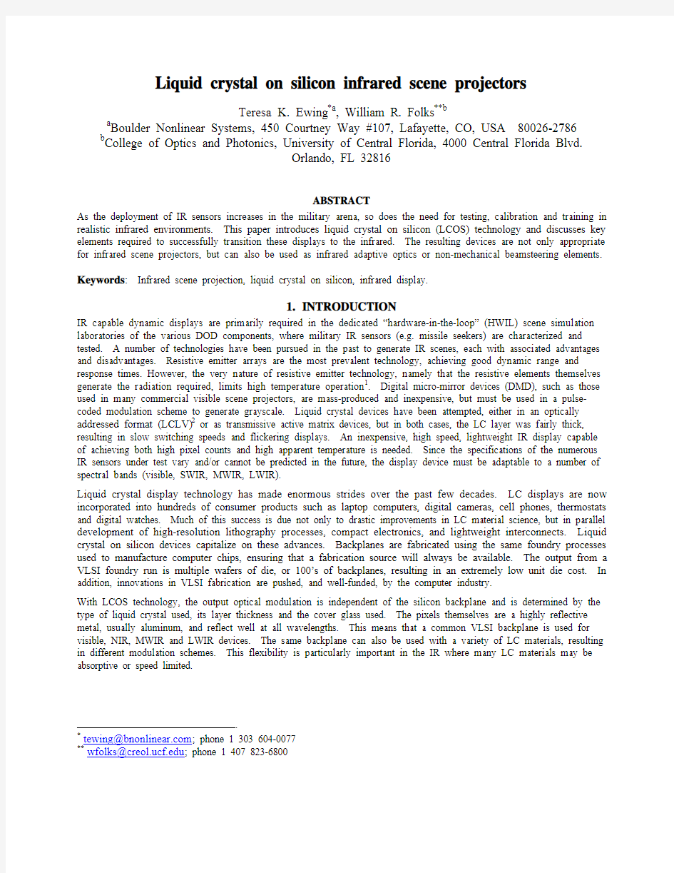
Teresa K. Ewing*a, William R. Folks**b
a Boulder Nonlinear Systems, 450 Courtney Way #107, Lafayette, CO, USA 80026-2786
b College of Optics and Photonics, University of Central Florida, 4000 Central Florida Blvd.
Orlando, FL 32816
ABSTRACT
As the deployment of IR sensors increases in the military arena, so does the need for testing, calibration and training in realistic infrared environments. This paper introduces liquid crystal on silicon (LCOS) technology and discusses key elements required to successfully transition these displays to the infrared. The resulting devices are not only appropriate for infrared scene projectors, but can also be used as infrared adaptive optics or non-mechanical beamsteering elements.
Keywords: Infrared scene projection, liquid crystal on silicon, infrared display.
1.INTRODUCTION
IR capable dynamic displays are primarily required in the dedicated “hardware-in-the-loop” (HWIL) scene simulation laboratories of the various DOD components, where military IR sensors (e.g. missile seekers) are characterized and tested. A number of technologies have been pursued in the past to generate IR scenes, each with associated advantages and disadvantages. Resistive emitter arrays are the most prevalent technology, achieving good dynamic range and response times. However, the very nature of resistive emitter technology, namely that the resistive elements themselves generate the radiation required, limits high temperature operation1. Digital micro-mirror devices (DMD), such as those used in many commercial visible scene projectors, are mass-produced and inexpensive, but must be used in a pulse-coded modulation scheme to generate grayscale. Liquid crystal devices have been attempted, either in an optically addressed format (LCLV)2 or as transmissive active matrix devices, but in both cases, the LC layer was fairly thick, resulting in slow switching speeds and flickering displays. An inexpensive, high speed, lightweight IR display capable of achieving both high pixel counts and high apparent temperature is needed. Since the specifications of the numerous IR sensors under test vary and/or cannot be predicted in the future, the display device must be adaptable to a number of spectral bands (visible, SWIR, MWIR, LWIR).
Liquid crystal display technology has made enormous strides over the past few decades. LC displays are now incorporated into hundreds of consumer products such as laptop computers, digital cameras, cell phones, thermostats and digital watches. Much of this success is due not only to drastic improvements in LC material science, but in parallel development of high-resolution lithography processes, compact electronics, and lightweight interconnects. Liquid crystal on silicon devices capitalize on these advances. Backplanes are fabricated using the same foundry processes used to manufacture computer chips, ensuring that a fabrication source will always be available. The output from a VLSI foundry run is multiple wafers of die, or 100’s of backplanes, resulting in an extremely low unit die cost. In addition, innovations in VLSI fabrication are pushed, and well-funded, by the computer industry.
With LCOS technology, the output optical modulation is independent of the silicon backplane and is determined by the type of liquid crystal used, its layer thickness and the cover glass used. The pixels themselves are a highly reflective metal, usually aluminum, and reflect well at all wavelengths. This means that a common VLSI backplane is used for visible, NIR, MWIR and LWIR devices. The same backplane can also be used with a variety of LC materials, resulting in different modulation schemes. This flexibility is particularly important in the IR where many LC materials may be absorptive or speed limited.
*tewing@https://www.360docs.net/doc/8a12181307.html,; phone 1 303 604-0077
**wfolks@https://www.360docs.net/doc/8a12181307.html,; phone 1 407 823-6800
2.LCOS DISPLAY OPERATION
Liquid Crystal on Silicon is the marriage of two components; liquid crystals, which have a voltage variable optical response, and VLSI backplanes, which provide active electronic circuitry in a compact package. Figure 1 shows a cross-section of a typical LCOS display. A thin layer of liquid crystal material is placed between a VLSI die and a cover glass. The VLSI die is basically an array of metal pixels that serve as both individual electrodes and mirrors. The cover glass is coated with a thin layer of conductive material, so thin in fact that the film is transparent. The individual pixels and the cover glass serve as electrodes on opposite sides of the liquid crystal layer. By changing the voltage at each pixel, one can manipulate the orientation of the liquid crystal molecules and in turn, can change the polarization of the light at that pixel. Light enters the display linearly polarized, travels through the cover glass, through the LC layer, is reflected off the pixels and returns back through the LC layer and cover glass. An exit polarizer is used to analyze the voltage induced polarization changes – thereby converting pixel by pixel polarizations into black, white or gray pixels.
Figure 1. Side view of a LCOS display.
3.TRANSITIONING LCOS TO THE IR
Liquid crystal on silicon is an attractive candidate for IR scene projection. In order to transition the LCOS devices from the visible to the infrared, however, several obstacles must be overcome. First, the materials commonly used to fabricate visible LCOS displays are not appropriate for the infrared. Secondly, the response time of existing visible LCOS displays are insufficient for the IR scene projector application
3.1.IR Absorption
Minimizing absorption in the LCOS display is important for two reasons. First, it is important to maximize the optical efficiency of the device. Second, absorption leads to local heating. This adds noise to the IR system, and can change the optical properties of the liquid crystal layer. By examining Figure 1, one can determine where in the light path one might encounter optical loss. At the air to cover glass interface, there will be Fresnel reflection due to the refractive index mismatch. This can reduced through the use of a suitable anti-reflection coating. The cover glass itself can be the source of absorption. In the visible, a fused silica cover glass is commonly used. However, fused silica absorbs in the infrared, therefore an alternative material must be found. An ideal candidate would not only be optically transparent in the IR, but would be transparent enough in the visible to facilitate fabrication and testing. In addition, the substrate material must be durable enough to withstand cleaning and the application of alignment layers and coatings. Hygroscopic (water-absorbing) materials are difficult to work with and are not appropriate for field deployable units. Compatibility of the substrates with transparent conductor films is another important consideration. After surveying available IR substrates, we found zinc selenide (ZnSe) to be the best candidate in the MWIR.
To successfully transition LCOS displays to the MWIR and LWIR, an IR compatible transparent conductive film must be found to serve as the common electrode. Transparent Conductive Oxides (TCO) are a class of thin film
semiconductor ceramics used in a variety of applications, including liquid crystal displays, anti-static films, anti-fog windows, and solar cells. These films are normally optimized for visible operation, but can be customized for IR applications 3. Film optimization focuses on optimizing the optical and electrical properties of the materials. The optical properties of interest include the transmission, reflectivity, and absorption of the film at a given IR wavelength (if used with an IR laser) or IR wavelength band (if used with a broadband radiator). The optical properties are primarily a factor of the base oxides used, and the film thickness. Of equal importance are the electrical properties, such as the conductivity and sheet resistance, which determines the switching dynamics of the common electrode. Low sheet resistances can be achieved by modify the film deposition processes or by reducing the film thickness, but ultimately one is limited by the mobility of the material itself. In addition, in a scene projection application, the spatial uniformity of these films must be insured as pixel-to-pixel variances cannot be tolerated. In practice, the availability, toxicity, reproducibility, and cost of the coating must also be considered.
In the MWIR, we have found a number of candidate TCO materials including In(Ti)O and In(Mo)O that have good mobility and can result in films with absorptions of less than 1%. In the LWIR, however, the outlook is not as
promising. Most TCO films have absorption of more than 8% in this region. One material, CdO has very high mobility and low absorption in the LWIR, but is a highly toxic material. An interesting alternative to a TCO in the long wave is to use a semiconductor as both the substrate and the common electrode. Both silicon and germanium are transparent in the LWIR and are electrical semi-conductors that can be doped to change their electrical properties. These materials could be used as both coverglass substrate and common electrode.
The liquid crystal materials also have some absorption in the infrared 4. For example, in the MWIR, absorption in the
3.4-3.6 μm range can be observed, due to molecular vibrations of CH, CH 2, and CH 3. There is also a strong absorption band, due to CN absorption, at
4.45 μm. In addition, there are several absorption bands in the 8-12 μm region. One solution is to shift the absorption bands out of the region of interest by modifying the molecular composition of the LC material
5. The effect of absorption bands can also be avoided altogether through the use of passive spectral filters or through the use of narrow-band laser illumination.
3.2. Response Time
Response time is the greatest concern when considering a liquid crystal based solution to the IR scene projection
problem. Although the response time of commercially available nematic LC materials is adequate for visible operation, IR operation requires a thicker LC layer, which greatly reduces the switching speed of the material. Response time of liquid crystal based devices is also a function of drive voltage. This can make high-speed operation with a standard VLSI 5V backplane difficult. Therefore, a successful device for the IR will require both a high-voltage backplane and high speed materials.
The most conventional liquid crystal display architecture is a homogenously aligned nematic liquid crystal display. The minimum thickness of the LC layer required for such a reflective LCOS device is a quarter wavelength thick, resulting in a half wavelength of phase modulation in the double pass through the device. The required thickness, d , can be determined by the equation:
n d ?=4λ
Where λ is the wavelength of the incident light and ?n is the birefringence of the liquid crystal. The speed of a given device is highly dependent on the LC layer thickness, d , and on material dependent properties, such as the threshold voltage (Vth), the rotational viscosity (γ1) and the elastic constant (K )6. Typically, the rise time (~1ms) is much faster than the decay time, and so in a display application, it is the decay time that is of concern. Maintaining a thin LC layer is very desirable as the resulting switching speed decreases as the square of the thickness. A high speed LC material would therefore need both low viscosity and a high birefringence to minimize LC layer thickness.
Two promising alternative LC materials are ferroelectric LC and dual-frequency nematic LCs. In conventional nematic LC materials, the molecules can be switched in one direction with the application of an electric, but relax back to their original configuration once the field is removed. Ferroelectric liquid crystal materials have permanent dipoles
perpendicular to the long axis of the molecules. This causes the material to exhibit a spontaneous polarization when subjected to an electric field. Unlike nematic LC materials, the molecules can be driven in both directions, resulting in
much faster switching speeds. Dual-frequency liquid crystal materials have a dielectric anisotropy that changes direction at a relatively low frequency. All nematic LC materials exhibit this type of behavior. However, the frequency and temperature where the cross over occurs is material dependent. Therefore, special mixtures have been developed to have a low frequency (around 10 KHz) cross-over point. These materials can likewise be driven in both directions, resulting in a rapid electro-optic response.
4.MWIR PROTOTYPE RESULTS
Figure 2. 256x256 FLC MWIR display.
To demonstrate the feasibility of a liquid crystal on silicon approach for IRSP applications, we fabricated three separate displays using a silicon backplane from BNS’ existing stock7. The backplane utilized is an array of 256x256 pixels, with a center to center pixel spacing of 24 microns. The backplane was fabricated using a custom high-voltage process, and can support a voltage of 13V at each pixel. Because of the thicker LC layers required for IR operation, a higher pixel voltage is a necessity. All three displays were then evaluated in the MWIR at Infrared Systems Laboratory at the University of Central Florida (CREOL).
Figure 3. MWIR images from LCOS displays (blackbody source).
The first display was manufactured with a commercial nematic LC (Merck E44) with a homogenous alignment. The cover glass was CaF2 with an ITO coating. The display was limited to the 13 V available on the VLSI backplane. This display had a measured response time of 92 ms, an order of magnitude slower than desired for the IRSP application. Therefore, an alternate strategy had to be found.
The University of Central Florida’s College of Optics has been developing innovative high speed materials to enable LC beamsteering devices8. These materials exhibit both high birefringence and low viscosity. A sample of high birefringence material was provided by UCF, and was incorporated into the second MWIR display. This material showed impressive improvement over the commercial material, with a switching time of 38 ms.
4.1. MTF Measurements
The modulation transfer function (MTF) of the UCF nematic display was measured. Modulation transfer function (MTF) is a convenient figure of merit used to measure system image quality. To test MTF, a series of vertical bar targets of increasing spatial frequency are used. This provides a good visual comparison of the desired driving image for the display and the result when viewed in the mid-wave (3-5) μm band. We used an input data set of square-wave bar targets and a frame-grabber to take a series of digital pictures of the resulting images on the display as shown in Table 1. On the left side of the table are arrayed pictures of input images to the display. On the right are shown corresponding results when viewed with the mid-wave IR camera looking into the LCOS display. At low spatial frequencies the wide vertical bars are reproduced quite well; there are some aliasing effects however at the transitions between adjacent bright and dark vertical bars. One can see quite clearly see progressive degradation of the images at higher spatial frequencies.
The LCOS device has 256x256 pixels with a pixel pitch of 24 μm. This puts a theoretical limit on the spatial frequency of 21 cycles/mm which could be displayed. It’s actually slightly less than this number because of the fill factor.
A line-by-line series of horizontal slices were extracted from images like those show above. The absolute value of the Fourier transform of each line scan was taken and averaged. This procedure is then repeated for each spatial frequency of interest. To avoid nonlinearity in the camera response the square-wave data sets used were at 40% modulation depth at the display input which is why the vertical bars show intermediate gray levels rather than hard black-to-white transitions. This technique reduces aliasing effects in the output image.
Modulation transfer function (MTF) is defined as the modulus of the complex optical transfer function (OTF) and is a convenient figure of merit used to measure system image quality. It may also be defined as the absolute value of the Fourier transform of the point spread function (PSF),
)(PSF MTF F =.
The advantage of the MTF approach is that the total system MTF is simply expressed as the product of each of the subsystem MTFs:
∏==n
i i System MTF MTF 1
.
This property allows for the MTF of each subsystem to be studied independently. For higher spatial frequencies we determined MTF as the magnitude of the fundamental component of the Fourier transform. This avoids the necessity of a series correction to convert square-wave to sine-wave data. As an alternative interpretation, for low spatial frequencies modulation transfer function may be approximated by the modulation depth:
MIN
MAX MIN MAX A A A A M +?=. Measurements were performed on the 256x256 display filled with the UCF material. The figure below shows MTF as a function of spatial frequency for our prototype display.
Input Bar Target File:Resulting IR Output Image:
0.38 cycles/mm
1.26 cycles/mm
4.7 cycles/mm
18.8 cycles/mm
Table 1. Input bar-target images used to drive the display, and their resulting images
as seen through the mid-wave IR camera.
One can see that the image quality begins to dramatically drop off near a spatial frequency of 5 cycles/mm. This represents a period of about 4 pixels. We observe the sharp knee and fall-off of the MTF curve specifically because this is a pixilated system. It is what one would expect rather than the gentler drop in MTF often seen in imaging system level such as microscopes or cameras. At small spatial distances less than a few pixels the ability of the system to properly image input information drops off sharply. Note that in Figure 4 the data point on the far right is beyond the limit of the device yet its MTF is reported as greater than zero. This represents the error in our measurement and computation method.
In summary, the main MTF limitations of our device are pixel pitch, fill factor and diffraction effects. Increasing device resolution and changing the design configuration for on-axis illumination/viewing should improve device performance.
4.2.High-Speed Material Investigation
Figure 5. Switching response of the MWIR FLC cell.
The IRSP application demands high speed operation. To achieve 200 Hz frame rates, an alternative to a standard nematic approach must be found. Both ferroelectric LC materials and dual-frequency materials are considered viable candidate to meet this demand. As part of our material investigation, we fabricated two MWIR test cells with high speed mixtures; one with a ferroelectric LC compound and a second with dual frequency LC material. Both cells were fabricated with CaF2 substrates with a thin ITO layer used as the transparent conductor. The ferroelectric cell required a thickness of 7 microns, a result of the relatively low MWIR birefringence of the material. However, the switching time was impressive, (see Figure 5) with a 2 ms activation time and a 1.5 ms deactivation time when subjected to a 13V field. The absorption of the FLC cell was measured by the University of Central Florida using a FITR spectrometer.
Those results are shown in Figure 6. Note the strong absorption at 3.4-3.6 μm, as is also seen in the nematic LC materials.
Figure 6. Transmission spectrum of the FLC cell.
The dual-frequency nematic cell was driven with a pulsed square toggling between 2 kHz and 40 kHz. The change in frequency changes the sign of the dielectric anisotropy of the material, causing the material to be driven in both directions. Initial measurement were made with a National Instrument card with a voltage limit of 20 V (see Figure 7). Even with this limited voltage, the material exhibited an activation time of 4ms and a deactivation time of 4 ms. Subsequent tests with a standalone function generator at 60V produced a deactivation time of 2 ms.
Figure 7. Response time of the MWIR Dual-Frequency nematic cell. Consequently, a third display was filled with the FLC mixture. The display also exhibited a 2 ms response time. However the display exhibited poor spatial uniformity due to poor alignment. In addition, the display exhibited a very limited grayscale response. Future efforts will concentrate on fabrication improvements and enhancing the grayscale response.
Figure 8. Grayscale response of the FLC display.
5.CONCLUSIONS
It has been demonstrated that liquid crystal on silicon devices can be transitioned to both the mid-wave and long-wave infrared bands. IR appropriate substrate materials, transparent conductive films and liquid crystals address absorption concerns. However, it is clear that a unique LC configuration will need to be pursued to meet the desired response time. Future efforts will focus high-speed LC materials and on the fabrication of a high resolution, high-voltage silicon backplane. This backplane is an essential component, irregardless of the LC architecture pursued. The complicated drive scheme required to support dual-frequency LC materials will also be developed. Additional goals are to increase the contrast ratio of the LCOS display, pursue IR transparent conductive films, develop high voltage drive electronics and pursue high temperature displays.
An interesting benefit from this research is the application of the devices as programmable phase modulators. With minor modifications, the IR displays can be configured to be IR programmable lenses, wavefront correctors9 and/or
non-mechanical beamsteering devices10. This could greatly enhance the capability of current IR sensor arrays, or could provide a solid-state option to mechanically scanned mirrors.
ACKNOWLEDGEMENTS
The authors would like to thank Steve Serati, Owais Mughal, Jim Brooks, Lance Hosting and Anna Linnenberger of BNS for their assistance with this program. For advice, technical expertise and for providing their innovative LC materials, we are grateful to Dr. Shin-Tson Wu and Dr. Sebastian Gauza of UCF/CREOL. In addition, we would like thank Dr. Glenn Boreman of UCF/CREOL for his guidance and access to his testing facility. Our thanks to Dr. Le Li of Kent Optronics, for his continued support and collaboration in this effort. For encouragement and advice, we would like to thank Dr. Donald Synder of AFRL/MN, and Winn Gaynor of MDA. Finally, we gratefully acknowledge the funding and support of Richard Brown of the U.S. Army/RTTC (contract #W31P4Q-04-C-R175), and Dr. Richard Curtis of the U.S. Army/SMDC (Contract #W9113M-04-P-0123).
REFERENCES
1 S. Solomon, “Adventures in High-Temperature Resistive Emitter Physics”, Proc. SPIE, 5092, pp. 52-60 (2003).
2 S.T. Wu, U. Efron, J. Grinberg, L. Hess and M. Welkowsky, “Infrared liquid crystal light valve,” SPIE Proc., 572,
pp. 94-101, (1985).
3 J. Perkins, C. Teplin, M. Van Hest, C. Warmsingh, D. Ginley and S. Harris,”Optimization of Transparent Conducting
Oxides for Liquid Crystal Based Optical Phased Arrays”, Proc. IEEE Aerospace Conference 2003, 5.0801, p. 4-1823, (2003).
4 S.T. Wu, “Infrared Properties of Nematic Liquid Crystals: an Overview,” Opt. Eng., 26, 2, pp. 120-128, (1987).
5 S.T. Wu, Q.H. Wang, M. Kempe and J. Kornfield, “Perdeuterated cyanobiphenyl liquid crystals for infrared
applications”, J. Appl. Phys.,92, 12, (2002).
6 S.T. Wu and D.K. Yang, Reflective Liquid Crystal Displays, John Wiley & Sons, 2001, pp 270-271.
7 S. Serati, X. Xia, O. Mughal, A. Linnenberger, “High-resolution phase-only spatial light modulators with sub-
millisecond response,” Proc. SPIE, 5106, pp. 138-145, (2003).
8 S. Gauza, H. Wang, C. H. Wen, S. T. Wu, A. Seed, and R. Dabrowski, “High birefringence isothiocyanato tolane
liquid crystals,” Jpn. J. Applied Physics, Part I 42, 3463-66 (June, 2003).
9 S. Serati, T. Ewing, and J. Stockley, “ New developments in high-resolution liquid-crystal spatial light modulators for
wavefront control,” 4825, pp. 46-55 (2002).
10 S. Serati, and J. Stockley, “Advanced liquid crystal on silicon optical phased arrays,” Proc. IEEE Aerospace
Conference 2002, 5.0301 (2002).
发酵消泡剂的使用方法
发酵消泡剂的使用方法 分类名称:sxp-101发酵消泡剂 品牌:*华**润* 活性成分:聚硅氧烷、分散剂、非离子表面活性剂 性状:本品为乳白色水包油型乳液,不挥发物:25±1%,PH值6-8,稳定性(3000转/20分钟):不分层,离子特性:非离子型。 用途:本品是专为发酵工艺而设计的一种高效有机硅消泡剂,用于各类发酵生产过程的消泡,如红霉素、洁霉素、阿维菌素、庆大霉素、青霉素、柠檬酸、赖氨酸、酵母生产等多种发酵消泡工艺,在兽药加工、后期提取工艺中也被广泛应用。 性能特点: 1、消泡快,用量少。 2、不影响起泡体系的基本性质。 3、扩散性、渗透性好。 4、化学性稳定,耐氧化性强。 5、无生理活性,无腐蚀、无毒、无不良副作用、不燃、不爆,安全性高。 性能特点: 本品消泡速度快、抑泡时间长、分散效果好;理化性质稳定,不与发泡体系中物质产生反应,不影响产品品质,能提高发酵微生物的发酵单位,促进菌丝生长,缩短发酵周期,对提高收率有益;同时,本品在经高温杀菌生,能自动恢复乳液状态,不会在添加罐中因油水分离、分层而影响效能。 在使用量适当的情况下,可以满足整个发酵周期控制泡沫的要求,不需添加泡敌(G·P·E 或P·P·E)类产品,是对泡敌毒性比较敏感的菌种发酵的最佳消泡剂。 使用方法: ①本品可在基础料中一次性添加;
②连续向发酵液中滴加或流加; ③使用数量:单独使用按配料体积的0.15%-0.2%;如配合0.01-0.03%的泡敌使用,按0.05-0.1%即可达到很好的消泡效果。 产品安全: ①建议在选用前,取发泡液小样模拟实际使用条件进行消泡试验及确定消泡剂的最佳 添加量。 ②②用于医药、食品方面消泡时,应严格按照药典及有关法规要求,在使用前应进行 消毒、灭菌处理。 包装贮运:25公斤塑桶或200公斤内涂塑铁桶包装;贮于阴凉处,按无毒、非危险品运输,注意防冻。 作者:宿州华润
BT152单向可控硅
GENERAL DESCRIPTION QUICK REFERENCE DATA Glass passivated thyristors in a plastic SYMBOL PARAMETER MAX.MAX.MAX.UNIT envelope,intended for use in applications requiring high BT152-400R 600R 800R bidirectional blocking voltage V DRM ,Repetitive peak off-state 450650800V capability and high thermal cycling V RRM voltages performance.Typical applications I T(AV)Average on-state current 131313A include motor control,industrial and I T(RMS)RMS on-state current 202020A domestic lighting,heating and static I TSM Non-repetitive peak on-state 200 200 200 A switching. current PINNING - TO220AB PIN CONFIGURATION SYMBOL LIMITING VALUES Limiting values in accordance with the Absolute Maximum System (IEC 134).SYMBOL PARAMETER CONDITIONS MIN.MAX. UNIT -400R -600R -800R V DRM Repetitive peak off-state -45016501800 V voltages I T(AV)Average on-state current half sine wave; T mb ≤ 103 ?C -13 A I T(RMS)RMS on-state current all conduction angles -20A I TSM Non-repetitive peak half sine wave; T j = 25 ?C prior to on-state current surge t = 10 ms -200A t = 8.3 ms -220A I 2t I 2t for fusing t = 10 ms -200A 2s dI T /dt Repetitive rate of rise of I TM = 50 A; I G = 0.2 A;-200A/μs on-state current after dI G /dt = 0.2 A/μs triggering I GM Peak gate current -5A V GM Peak gate voltage -5V V RGM Peak reverse gate voltage -5V P GM Peak gate power -20W P G(AV)Average gate power over any 20 ms period -0.5W T stg Storage temperature -40150?C T j Operating junction -125 ?C temperature 1 Although not recommended, off-state voltages up to 800V may be applied without damage, but the thyristor may switch to the on-state. The rate of rise of current should not exceed 15 A/μs.
双向可控硅选型表要点
双向可控硅为什么称为“TRIAC”? 三端:TRIode(取前三个字母) 交流半导体开关:AC-semiconductor switch(取前两个字母) 以上两组名词组合成“TRIAC”,或“TRIACs”中文译意“三端双向可控硅开关”。 由此可见“TRIAC”是双向可控硅的统称。 另: 双向:Bi-directional(取第一个字母) 控制:Controlled (取第一个字母) 整流器:Rectifier (取第一个字母) 再由这三组英文名词的首个字母组合而成:“BCR”,中文译意:双向可控硅。 以“BCR”来命名双向可控硅的典型厂家如日本三菱,如:BCR1AM-12、BCR8KM、BCR08AM 等等。 -------------- 双向:Bi-directional (取第一个字母) 三端:Triode (取第一个字母) 由以上两组单词组合成“BT”,也是对双向可控硅产品的型号命名,典型的生产商如:意法ST公司、荷兰飞利浦-Philips公司,均以此来命名双向可控硅. 代表型号如:PHILIPS 的BT131-600D、BT134-600E、BT136-600E、BT138-600E、BT139-600E、、等。这些都是四象限/非绝缘型/双向可控硅;Philips公司的产品型号前缀为“BTA”字头的,通常是指 三象限的双向可控硅。三象限的品种主要应用于电机电路、三相市电输入的电路、承受的瞬间浪涌电流高。 ------------------- 而意法ST公司,则以“BT”字母为前缀来命名元件的型号,并且在“BT”后加“A”或“B”来表示绝缘与非绝缘。组成:“BTA”、“BTB”系列的双向可控硅型号,如: 四象限、绝缘型、双向可控硅:BTA06-600C、BTA08-600C、BTA10-600B、BTA12-600B、BTA16-600B、BTA41-600、、、等等; 四象限、非绝缘、双向可控硅:BTB06-600C、BTB08-600C、BTB10-600B、BTB12-600B、BTB16-600B、BTB41-600、、、等等; ST公司所有产品型号的后缀字母(型号最后一个字母)带“W”的,均为“三象限双向可控硅”。如“BW”、“CW”、“SW”、“TW”; 代表型号如:BTB12-600BW、BTA26-700CW、BTA08-600SW、、、、等等。 至于型号后缀字母的触发电流,各个厂家的代表含义如下: PHILIPS公司:D=5mA,E=10mA,C=15mA,F=25mA,G=50mA,R=200uA或5mA,型号没有后缀字母之触发电流,通常为25-35mA; PHILIPS公司的触发电流代表字母没有统一的定义,以产品的封装不同而不同。 意法ST公司:TW=5mA,SW=10mA,CW=35mA,BW=50mA,C=25mA,B=50mA,H=15mA,T=15mA, 注意:以上触发电流均有一个上下起始误差范围,产品PDF文件中均有详细说明,一般分为最小值/典型值/最大值,而非“=”一个参数值。 对于产品类别、品种系列的名词国际上通用的命名有:
有机硅消泡剂的使用注意事宜
有机硅消泡剂的使用注意事宜 有机硅消泡剂系由硅油、白碳黑、乳化剂、分散剂、防腐剂、增稠剂等配以适量水经机械乳化而成。它的特点是表面张力小,表面活性高,消泡力强,用量少,成本低。对大多数气泡介质均能消泡和抑泡。 有机硅消泡剂系由硅油、白碳黑、乳化剂、分散剂、防腐剂、增稠剂等配以适量水经机械乳化而成。它的特点是表面张力小,表面活性高,消泡力强,用量少,成本低。对大多数气泡介质均能消泡和抑泡。它具有较好的热稳定性,可在-5℃~-150℃宽广的温度范围内使用;有机硅的化学稳定性较好,难与其他物质反应,只要配置适当,可在酸、碱、盐溶液中使用,无损产品质量;它还具有生理惰性,通常用于食品和医药行业。它对所有气泡体系兼具有抑泡、破泡功能,隶属广谱型消泡剂范畴。它被广泛用于线路板清洗、纺织印染、造纸纸浆、电镀、化肥、助剂、污水处理等生产过程中的消泡抑泡。 有机硅消泡剂是消泡剂家族中最庞大,使用最广,产量和销量最大,最常见的一种消泡剂,所以在使用有机硅消泡剂时应该注意以下事宜: 第一,在使用或采样前需要充分搅匀乳液。 第二,虽然水包油型乳液可任意稀释,但同时乳液的稳定性也会因此急剧下降,如发生分层等,所以在稀释时请将水加入消泡剂中并缓慢搅拌。最好加入增稠剂,以提高其稳定性。 第三,由于乳液在原始浓度下稳定性最好,所以稀释后的乳液必须在短期内用完。 第四,防止霜冻!乳液对霜冻和温度高于40°C都很敏感而易遭到破坏。如果已经冻住的乳液可以小心地去霜冻,但在进一步使用前必须作检测。 第五,长时间强烈振荡或强烈剪切(如使用机械泵,均质机等)或搅拌会破坏乳液的稳定性。 第六,如果想要提高乳液的稳定性,可以添加增稠剂以提高乳液的粘度。
新型高分子材料有机硅
新型高分子材料有机硅 姓名:王伟坤 学院:化科院 专业:化学类 学号:08130203 老师:周宁琳 摘要 有机硅聚合物是特种高分子材料,是分子结构中含有元素硅的高分子合成材料,一般系指聚硅氧烷而言。包括硅油、硅橡胶、硅树脂、硅烷偶联剂四大门类几千个品种牌号。它是在第二次世界大战期间作为飞机、火箭的特殊材料而发展起来的。经过40多年的开发研究,现在不仅广泛用于各种现代工业、新兴技术和国防军工中,而且还深入到我们的日常生活中,成为化工新材料中的佼佼者。 关键词:有机硅有机硅活化剂 有机硅发展简史 硅是世界上分布最广的元素之一,其熔点为1420℃,其丰度仅次于氧(约含 49.5%)而占第二位,在地壳中约含25.8%;而碳仅占0.087%。自然界没有游离的硅,主要以二氧化硅和硅酸盐存在,自然界中常见的硅化合物有石英石、长石、云母、滑石粉等耐热难熔的硅酸盐材料。硅可以说是组成地壳的最主要元素之一。18世纪下叶,当化学家都在竞相研究有机化合物时,C.Friedel,J.M.Crafts, https://www.360docs.net/doc/8a12181307.html,denberg,F.S.Kipping等作了大量的工作,他们已注意到了硅和碳化合物的区别,并进行了广泛、深入地研究。特别是英国诺丁汉大学的F.S.Kipping的工作奠定了有机硅化学的基础。 科学家对有机化合物和有机高分子聚合物广泛深入研究的结果促进了有机合成材料如酚醛、聚酯、环氧、聚氨酯等树脂及各种合成塑料、合成橡胶、合成纤维的开发、生产和应用,使人类社会步入了合成材料时代。由于科技的高速发展,促进了经济的发展,虽然提高了效率,可是电机的温度上升了,普通材料不能胜任,所以迫切需要开发新的耐热合成材料。美国康宁玻璃厂实验室的G.F.Hyde.通用电气公司的
六甲基二硅烷胺
1、物质的理化常数 国标编号: 32185 CA S: 999-97-3 中文名称: 六甲基二硅烷胺 英文名称: 1,1,1,3,3,3-Hexamithyl disilazane;Hexamethyl disilylamine 别名: 六甲基二硅亚胺 分子式: C 6H 19 NSi 2 ;[(CH 3 ) 2 Si] 2 NH 分子 量: 161.40 熔点: 126℃ 密度: 相对密度(水=1)0.77 蒸汽压: 25℃ 溶解性: 溶于多数有机溶剂 稳定性: 稳定 外观与性状: 无色透明易流动液体,与空气接触会迅速分解为三甲基硅醇和六甲基二硅醚 危险标记: 7(易燃液体) 用途: 用作分析试剂和作为有机合成中间体 2.对环境的影响: 一、健康危害 侵入途径:吸入、食入、经皮吸收。 健康危害:吸入、摄入或经皮肤吸收后对身体有害。液体及蒸气对眼、皮肤和呼吸系统有刺激作用。吸入后可引起喉、支气管的炎症、水肿、痉挛,化学性肺炎、肺水肿等。 二、毒理学资料及环境行为 毒性:具刺激作用。 危险特性:遇明火、高热或与氧化剂接触,有引起燃烧的危险。若遇高热,容器内压增大,有开裂和
爆炸的危险。遇低级醇和水起化学反应而分解。 燃烧(分解)产物:一氧化碳、二氧化碳、氧化氮、氧化硅。 3.现场应急监测方法: 4.实验室监测方法: 5.环境标准: 6.应急处理处置方法: 一、泄漏应急处理 疏散泄漏污染区人员至安全区,禁止无关人员进入污染区,切断火源。应急处理人员戴自给式呼吸器,穿化学防护服。不要直接接触泄漏物。在确保安全情况下堵漏。用不燃性分散剂制成的乳液刷洗,经稀释的洗液放入废水系统。如大量泄漏,利用围堤收容,然后收集、转移、回收或无害处理后废弃。 二、防护措施 呼吸系统防护:可能接触其蒸气时,应该佩带防毒面具。紧急事态抢救或撤离时,建议佩戴自给式呼吸器。 眼睛防护:戴化学安全防护眼镜。 身体防护:穿防静电工作服。 手防护:戴橡皮手套。 其它:工作后,淋浴更衣。注意个人清洁卫生。 三、急救措施 皮肤接触:脱去污染的衣着,用肥皂水及清水彻底冲洗。 眼睛接触:立即翻开上下眼睑,用流动清水冲洗15分钟。就医。 吸入:迅速脱离现场至空气新鲜处。呼吸困难时给输氧。呼吸停止时,立即进行人工呼吸。就医。
最新单向可控硅和双向可控硅原理及应用大全
可控硅元件的工作原理及基本特性 1、工作原理 可控硅是P1N1P2N2四层三端结构元件,共有三个PN结,分析原理时,可以把它看作由一个PNP管和一个NPN管所组成,其等效图解如图1所示
图1 可控硅等效图解图 当阳极A加上正向电压时,BG1和BG2管均处于放大状态。此时,如果从控制极G 输入一个正向触发信号,BG2便有基流ib2流过,经BG2放大,其集电极电流 ic2=β2ib2。因为BG2的集电极直接与BG1的基极相连,所以ib1=ic2。此时,电流ic2再经BG1放大,于是BG1的集电极电流ic1=β1ib1=β1β2ib2。这个电流又流回到BG2的基极,表成正反馈,使ib2不断增大,如此正向馈循环的结果,两个管子的电流剧增,可控硅使饱和导通。 由于BG1和BG2所构成的正反馈作用,所以一旦可控硅导通后,即使控制极G的电流消失了,可控硅仍然能够维持导通状态,由于触发信号只起触发作用,没有关断功能,所以这种可控硅是不可关断的。 由于可控硅只有导通和关断两种工作状态,所以它具有开关特性,这种特性需要一定的条件才能转化,此条件见表1 表1 可控硅导通和关断条件 状态条件说明从关断到导通 1、阳极电位高于是阴极电位 2、控制极有足够的正向电压和电流 两者缺一不可维持导通 1、阳极电位高于阴极电位 2、阳极电流大于维持电流 两者缺一不可从导通到关断 1、阳极电位低于阴极电位 2、阳极电流小于维持电流
任一条件即可 2、基本伏安特性 可控硅的基本伏安特性见图2 图2 可控硅基本伏安特性 (1)反向特性 当控制极开路,阳极加上反向电压时(见图3),J2结正偏,但J1、J2结反偏。此时只能流过很小的反向饱和电流,当电压进一步提高到J1结的雪崩击穿电压后,接差J3结也击穿,电流迅速增加,图3的特性开始弯曲,如特性OR段所示,弯曲处的电压URO叫“反向转折电压”。此时,可控硅会发生永久性反向击穿。 图3 阳极加反向电压 (2)正向特性 当控制极开路,阳极上加上正向电压时(见图4),J1、J3结正偏,但J2结反偏,这与普通PN结的反向特性相似,也只能流过很小电流,这叫正向阻断状态,当电压增加,图3的特性发生了弯曲,如特性OA段所示,弯曲处的是UBO叫:正向转折电压 图4 阳极加正向电压
三端双向可控硅进行可靠操作的设计规则
三端双向可控硅进行可靠操作的设计规则 1,正确触发 要打开一个双向可控硅开,栅极驱动电路必须提供一个“活力”的栅极电流来保证快速有效的触发。 栅极电流的振幅: 门极电流(IG)要比指定的最大门触发电流高得多(IGTmax)。此参数是温度Tj = 25度时给定的。 在较低的温度下,用曲线表现为门极触发电流随温度的相对变化。设计预期的最低工作温度的栅极驱动。高IG值提供了一个高效触发(看§2)。 作为一个实际的原则,我们建议: 门电路的设计:
VOL = output voltage of the microcontroller (at 0 logic level) VOL=微处理器的输出电压 VG = voltage across the gate of the triac. Take the specified VGT. 在双向晶闸管的栅极电压。采取指定的VGT IG = required gate current (IG > 2. IGT max)所需的栅极电流 栅极电流持续时间: (对于ON-OFF开关) 脉宽的操作可以明显的降低栅极驱动功耗。 采用栅电流Ig直到负载电流达到闭锁电流(IL) 建议使用连续的栅极直流电流,避免流过的负载电流(IT < 50 or 100 mA)低于维持电流和擎住电流而引起电流的不连续性。 象限: 在新的项目中,为了是双向可控硅高性能运行,应避免在第4象限工作,仅在指定的1、2、3象限。2,平滑导通 当可控硅导通,确保了通态电流上升率不超过规定的最高值。例如在有缓冲网络跨接在双向可控硅时,在电容放电的情况下,检查这一点是非常重要的。 如果di / dt的超过规定值,然后栅区周围的电流密度过高时,产生过热。高重复性的di / dt可能引起硅晶片的逐步退化,引起栅极电流的增加和阻断能力的丧失。 在大多数情况下开关零电压大大降低了通态di / dt和浪涌电流。 提醒: &一个强大的栅极电流提高了可控硅的di / dt的能力,并提高通态的换向的可靠性:IG >> IGT (at least 2 or 3 times IGT max,至少2或3倍IGT max)。 &在三端双向可控硅跨接有RC网络的情况下,串联电阻的值必须足以限制通过双向可控硅的峰值电流和di / dt。 我们推荐: *在门极两端不要使用电容。 该电容显著降低di / dt的能力,此外,这种电容并不能改善静态dv / dt特性。 图2 为了尽量减少在打开时的di / dt的应力: R必须是大于47Ω更高; 不能并接栅极电容(CGK)
流平剂
简介 英文专业名称:Leveling agent. 流平剂是一种常用的涂料助剂,它能促使涂料在干燥成膜过程中形成一个平整、光滑、均匀的涂膜。流平剂种类很多,不同涂料所用的流平剂种类也不尽相同。 流平剂概述 涂料施工后,有一个流动及干燥成膜过程,然后逐步形成一个平整、光滑、均匀的涂膜。涂膜能否达到平整光滑的特性,称为流平性。缩孔是涂料在流平与成膜过程中产生的特性缺陷之一。在实际施工过程中,由于流平性不好,刷涂时出现刷痕,滚涂时产生滚痕、喷涂时出现桔皮,在干燥过程中相伴出现缩孔、针孔、流挂等现象、都称之为流平性不良,这些现象的产生降低了涂料的装饰和保护功能。 影响涂料流平性的因素很多,溶剂的挥发梯度和溶解性能、涂料的表面张力、湿膜厚度和表面张力梯度、涂料的流变性、施工工艺和环境等,其中最重要的因素是涂料的表面张力、成膜过程中湿膜产生的表面张力梯度和湿膜表层的表面张力均匀化能力。改善涂料的流平性需要考虑调整配方和加入合适的助剂,使涂料具有合适的表面张力和降低表面张力梯度的能力。 流平剂机理 涂料干燥成膜过常见的缺陷有缩孔、桔皮、刷痕、滚痕、流挂等。 缩孔是指涂膜上形成的不规则的,有如碗状的小凹陷,使涂膜失去平整性,常以一滴或一小块杂质为中心,周围形成一个环形的棱。从流平性的角度而言,它是一种特殊的“点式”的流不平,产生于涂膜表面,其形状从表现可分为平面式,火山口式,点式,露底式,气泡式等。 [编辑本段] 常用的防缩孔流平剂 溶剂类流平剂主要是高沸点溶剂混合物。溶剂型涂料仅借助增加溶剂以降低粘度来改善流平性,将使涂料固体分下降并导致流挂等弊病;或者保持溶剂含量,只加入高沸点溶剂以图调整挥发速度来改善流平,干燥时间也相应延长。故此两方案均不理想。只有加入高沸点溶剂混合物,显示各种递增特性(挥发指数、蒸馏曲线、溶解能力)较为理想。溶剂类流平剂主要成分是各种高沸点的混合溶剂,具有良好的溶解性,也是颜料良好的润湿剂。常温固化涂料由于溶剂挥发太快,涂料粘度提高过快妨碍流动而造成刷痕,溶剂挥发导致基料的溶解性变差而产生的缩孔,或在烘烤型涂料中产生沸痕、起泡等弊病采用这类助剂是很有效的。另外采用高沸点流平剂调整挥发速度,还可克服泛白弊病。
有机硅消泡剂常用的分类
有机硅消泡剂常用种类 SXP有机硅消泡剂 分类名称:通用型有机硅消泡剂 活性成分:改性聚硅氧烷、分散助剂、非离子表面活性剂 性状:本品为乳白色水包油型乳状液;有效成分30%;PH值:6-8;稳定性(3000转/20分钟):不分层;离子特性:非离子型。 用途:可广泛地应用于混凝土外加剂;废水处理;印染;造纸;纺织浆料;水性涂料;油田钻井液;化工;医药、农药发酵、农药乳液;乳化沥青;皮革处理;树脂、乳液聚合;矿物浮选;以及各种金属清洗液、切磨削液、胶粘剂、冷却液、日化洗涤剂等水基体系方面的消泡。 性能特点:本品系引进先进技术,100%采用进口原料所生产。能够迅速消除水相泡沫,长久抑泡。用量少,扩散性、渗透性好、耐热性好、化学性稳定、耐氧化性强。无腐蚀、无毒、无不良副作用,安全性高。在酸、碱、盐、电解质及硬水中都能使用。不影响起泡体系的基本性质。 使用方法:使用时建议将所需份量消泡剂用发泡液或清洁冷水稀释1:5的溶液使用,建议用量为0.5~1‰左右 包装储运:25kg塑料桶或200kg内涂塑铁桶装;在凉暗处保存,按无毒、非危险品运输,注意防冻。 SXP-101发酵消泡剂 分类名称:发酵用有机硅消泡剂 活性成分:聚硅氧烷、分散剂、非离子表面活性剂 性状:本品为乳白色水包油型乳液,不挥发物:25±1%,PH值6-8,稳定性(3000转/20分钟):不分层,离子特性:非离子型。
用途:本品是专为发酵工艺而设计的一种高效有机硅消泡剂,用于各类发酵生产过程的消泡,如红霉素、洁霉素、阿维菌素、庆大霉素、青霉素、柠檬酸、赖氨酸、酵母生产等多种发酵消泡工艺,在兽药加工、后期提取工艺中也被广泛应用。 性能特点:本品消泡速度快、抑泡时间长、分散效果好;理化性质稳定,不与发泡体系中物质产生反应,不影响产品品质,能提高发酵微生物的发酵单位,促进菌丝生长,缩短发酵周期,对提高收率有益;同时,本品在经高温杀菌生,能自动恢复乳液状态,不会在添加罐中因油水分离、分层而影响效能。在使用量适当的情况下,可以满足整个发酵周期控制泡沫的要求,不需添加泡敌(G·P·E或P·P·E)类产品,是对泡敌毒性比较敏感的菌种发酵的最佳消泡剂。 使用方法:①本品可在基础料中一次性添加;②连续向发酵液中滴加或流加;③使用数量:单独使用按配料体积的0.15%-0.2%;如配合0.01-0.03%的泡敌使用,按0.05-0.1%即可达到很好的消泡效果。 产品安全:①建议在选用前,取发泡液小样模拟实际使用条件进行消泡试验及确定消泡剂的最佳添加量。②用于医药、食品方面消泡时,应严格按照药典及有关法规要求,在使用前应进行消毒、灭菌处理。 包装贮运:25公斤塑桶或200公斤内涂塑铁桶包装;贮于阴凉处,按无毒、非危险品运输,注意防冻。 SXP-103水处理消泡剂 分类名称:水处理用有机硅消泡剂 活性成分:聚硅氧烷、分散剂、乳化剂、表面活性剂
涂料助剂 Paint additives Coating additives
涂料助剂Paint additives Coating additives 涂料助剂是涂料不可缺少的组分,它可以改进生产工艺,保持贮存稳定,改善施工条件,提高产品质量,赋予特殊功能。合理正确选用助剂可降低成本,提高经济效益。 又称油漆辅料,系配制涂料的辅助材料,能改进涂料性能,促进涂膜形成。种类很多,包括催干剂、增韧剂、乳化剂、增稠剂、颜料分散剂、消泡剂、流平剂、抗结皮剂、消光剂、光稳定剂、防霉剂、抗静电剂(见塑料助剂)等,其中用量最大的是催干剂和增韧剂。当前,涂料助剂的研究,以用于水乳胶漆的助剂为重点。 编辑本段种类 经多年发展,涂料助剂种类众多,而且在涂料生产的各个阶段都发挥了不同的作用。制造阶段有:引发剂、分散剂、酯交换催化剂;反应过程有:消泡剂、乳化剂、过滤助剂等;贮存阶段有:防结皮剂、防沉淀剂、增稠剂、触变剂、防浮色发花剂、抗胶凝剂等;施工阶段有:流平剂、防缩孔剂、防流挂剂、锤纹助剂、流动控制剂、增塑剂、消泡剂等;成膜阶段有:聚结助剂、附着力促进剂(也叫附着力增进剂)、光引发剂、光稳定剂、催干、增光、增滑、消光、固化、交联、催化等助剂;赋予特殊功能方面有:阻燃、杀生物、防藻、抗静电、导电、腐蚀抑制、防锈等助剂。[1] 笼统来说,按照其用途划分包括附着力增进剂,防粘连剂,防缩孔剂,防发花剂,防浮色剂,消泡剂,抑泡剂,抗胶凝剂,黏度稳定剂,抗氧剂,防结皮剂,防流挂剂,防沉淀剂,抗静电剂,导电控制剂,防霉剂、防腐剂,聚结助剂,腐蚀抑制剂,防锈剂,分散剂、润湿剂,催干剂,阻燃剂,流动控制剂,锤纹助剂,流干剂,消光剂,光稳定剂、光敏剂,光学增亮剂,增塑剂,增滑剂、防划伤剂,增稠剂,触变剂,其他助剂。 除了主要成膜物质、颜填料、溶剂之外,一种添加到涂料中去的成分,能使涂料或涂膜的某一特定性能起到明显改进作用的物质。在涂料配方中的用量很小。主要是多种无机化合物和有机化合物,包括高分子聚合物。 其名称大都根据其作用特性命名。改善涂料生产工艺的有湿润剂、分散剂、乳化剂、消泡剂等。改善涂料贮存性能和运输的有防沉剂、防结皮剂、防腐剂、冻融稳定剂等。改善涂料施工性能和防止漆膜病态的有防流挂剂、流平剂、浮色发花防止剂、消泡剂、增稠剂等。改善涂膜性能并给以特种性能的有紫外线吸收剂、光稳定剂、阻燃剂、抗静电剂、防霉剂等。 涂料助剂又可以分为油性涂料助剂和水性涂料助剂。顺应全球对环境保护日益重视,水性涂料助剂的发展有了飞跃的发展。新型环保类型的助剂越来越多。应用也越来越广泛。是涂料助剂今后发展的主流方向。 编辑本段详细介绍 催干剂 一类能加快涂膜干结的物质,对于干性油膜的吸收氧和双键的聚合起促进作用。它可使油膜的干结时间由数日缩短到数小时,施工方便且可防止未干涂膜的沾污和损坏。 许多金属的氧化物、盐类和皂类都有催干作用,但有实用价值的是氧化铅(红丹、黄丹)、二氧化锰、醋酸铅、硝酸铅、硫酸锰、氯化锰、硼酸锰、醋酸锰、醋酸钴、氯化钴以及铅、钴、锰的环烷酸皂、亚麻油酸皂和松香酸皂。 由于皂类催干剂油溶性好,故催干效力较高。现代涂料工业多采用环烷酸皂作催干剂。环烷酸皂通常用复分解法生产。 油性涂料中催干剂的用量依干性油或半干性油的数量而定。以干性的亚麻油为例,铅催干剂的用量(以铅计)为油质量的0.4~0.5%。钴和锰的催干能力强于铅,钴、锰、铅之比大约为8:1:40。两种或三种金属皂类并用有协同作用。在树脂涂料中,须增大催干剂用量。增韧剂 即增塑剂(见塑料助剂)。涂料工业常用的品种有邻苯二甲酸二乙酯、邻苯二甲酸二丁
新型消泡剂——有机硅消泡剂
新型消泡剂——有机硅消泡剂 简介: 消泡剂是一种以低浓度加入发泡体系中破坏或抑制泡沫的物质,按其状态可分为油状、乳液状、固体、膏状等,有机硅消泡剂是含硅表面活性剂,作为有机硅化合物中的一族,是一种新型消泡剂。从60年代起就用于各工业领域,但大规模和全面的快速发展,是从80年代开始的。作为有机硅消泡剂,其应用领域也十分广泛,越来越受到各行各业的重视。 特性: ①具有良好的化学惰性,一般不与被消泡的介质(不同的pH值、温度下)发生化学反应; ②具有正铺展系数,能在发泡系统中的气-液界面迅速铺展开; ③具有较低的表面张力,硅油的表面张力为1.520×10⁻⁵N/cm; ④不易被发泡体系中存在的表面活性剂所增溶。 消泡机理: 当体系加入消泡剂后,其分子杂乱无章地广布于液体表面,抑制形成弹性膜,即终止泡沫的产生。当体系大量产生泡沫后,加入消泡剂,其分子立即散布于泡沫表面,快速铺展,形成很薄的双膜层,进一步扩散、渗透,层状入侵,从而取代原泡膜薄壁。由于其表面张力低,便流向产生泡沫的高表面张力的液体,这样低表面张力的消泡剂分子在气液界面间不断
扩散、渗透,使其膜壁迅速变薄,泡沫同时又受到周围表面张力大的膜层强力牵引,这样,致使泡沫周围应力失衡,从而导致其“破泡”不溶于体系的消泡剂分子,再重新进入另一个泡沫膜的表面,如此重复,所有泡沫全部覆灭。 分类及性能: ?油状有机硅消泡剂 油状有机硅消泡剂可分为油型和油复合型。纯硅油对水溶液的泡沫无消泡作用,但在硅油中混入经疏水处理过的二氧化硅助剂,形成油复合型消泡剂,由于二氧化硅表面烃基有利于硅油的分散,从而改善了硅油的消泡性能,并且降低了原料成本。油状有机硅消泡剂的分子量大小对其消泡效果有一定的影响。分子量小,易于分散和溶解,但缺乏持久性;相反,分子量大则消泡性能差,同时乳化困难,但溶解性差,持久性好。实验测定,在强碱性的三乙醇胺水溶液发泡体系中,甲基硅油先于聚二甲基硅氧烷而达到消泡效果。 ?乳液有机硅消泡剂 由于油状有机硅消泡剂应用于水相,大多数受到分散性差等因素的影响,所以,寻求能改善这种局面的添加剂,使其形成乳液有机硅消泡剂。乳液有机硅消泡剂既能应用于非水相,又能适用于水相,在此方面,国内有很多的相关报道。在系列化的甲基硅油水乳化硅油中,乳化硅油302-30,302-20,304,既可用于非水相,又可用于水相,且具有润滑性好、对生物无毒害作用、不易挥发、不腐蚀金属、耐热、抗氧化等性能。 ?固体有机硅消泡剂 固体有机硅消泡剂制备工艺简单,贮存稳定性好,便于运输,通过改变其载体或助剂,既能用于水相,又能用于油相,且有较好的介质分散性,因此,固体有机硅消泡剂除用于无泡、低泡洗衣粉生产外,也已向其他使用液体消泡剂的领域渗透。固体有机硅消泡剂的制备方法可分为三种:①活性组分直接分散在固体载体表面;②活性组分与软化点较低的脂肪醇、脂肪酸、脂肪酰胺、脂肪酸酯、石蜡等物质一起熔融,再将熔融体附着在载体的表面; ③活性组分与成膜物质混合,使成膜物质包封在消泡组分的外部。其中,第一种方法制备的消泡剂适用温度范围宽,第三种方法制备的消泡剂稳定性强。 技术指标: 使用方法:
聚硅氧烷季铵盐整理剂的应用工艺研究(1)
聚硅氧烷季铵盐整理剂的应用工艺研究 学院:纺织与材料学院 班级:轻化工程12级03班 姓名:闫乐乐 学号: 41201030317 指导老师:习智华
摘要:本文介绍了聚硅氧烷季铵盐整理剂的理化性质,说明了聚硅氧烷季铵盐整理剂中的有效化学结构,阐述了纺织品多功能整理剂聚硅氧烷季铵盐使纺织品获得集柔软性、抗菌性、亲水性、抗静电性等优良性能于一体的抗菌整理功能的原理,通过对聚硅氧烷季铵盐整理剂工艺条件对织物应用性能的影响,确定棉织物的最佳整理工艺为:纺织品准备→浸轧整理液(20g/L,45℃,轧液率75%)→预烘(80℃,3min)→焙烘(120℃,120s)。 关键词:抗菌整理剂聚硅氧烷季铵盐性能工艺纯棉织物 1.背景: 这些年来,随着人们物质生活水平的不断提高,人们越来越追求织物的安全舒适性、以及抗菌抑菌环保性。众所周知,我们平时穿的衣服上,或者是所接触到的纺织品上总是存在着各种各样的的微生物,虽然大多数微生物是非致病的,但是在人体皮肤的汗液、代谢细胞废屑以及皮脂的滋养下,会大量繁殖,从而对人体皮肤产生不良的刺激,再加上细菌代谢分解产生的臭味,更容易让人感到异常不适,甚至更严重的时候会引发皮肤病、传染病,从而影响人们的日常生活。因此,纺织品的抗菌抑菌整理工艺技术的研究以及抗菌抑菌整理剂的研发 显得尤为重要,也迫在眉睫。无机型、双胍型、季铵盐型以及有机硅季铵盐类是我们常用在纺织品整理中的抗菌整理剂。一般的季铵盐型抗菌整理剂因为他的化学活性偏低,在抗菌整理过程中通常以游离态存在的,将其应用在纺织品上的时候也是溶出型的,整理剂容易被洗除,抗菌效果的持久性较差,并且在穿着的过程中容易富集在人体表面,再加之它较大的刺激性和毒性,如果长期使用,会产生病变。然而有机硅季铵盐类抗菌整理剂却能有效的避免上述问题的发生,因为属于非溶出型的抗菌整理剂,它是有机硅通过改性后的产品,是集有机硅赋予织物柔软、滑顺、抗静电等的优良性能和季铵基团的杀菌特性于一体的新型的阳离子型表面活性剂。它凭借自己优良的抗菌效果及持久抗菌性,具有很大的应用空间,同时它还有很广泛的应用范围,
单向可控硅与双向可控硅结构电原理图及测试方法
单向可控硅与双向可控硅结构电原理图及测试方法 可控硅的检测 1.单向可控硅的检测 万用表选用电阻R×1档,用红黑两表笔分别测任意两引脚间正反向电阻直至找出读数为数十欧姆的一对引脚,此时黑笔接的引脚为控制极G,红笔接的引脚为阴极K,另一空脚为阳极A。此时将黑表笔接已判断了的阳极A,红表笔仍接阴极K。此时万用表指针应不动。用短接线瞬间短接阳极A和控制极G,此时万用表指针应向右偏转,阻值读数为10欧姆左右。如阳极A接黑表笔,阴极K接红表笔时,万用表指针发生偏转,说明该单向可控硅已击穿损坏
。 2.双向可控硅的检测 用万用表电阻R×1档,用红黑两表笔分别测任意两引脚正反向电阻,结果其中两组读数为无穷大。若一组为数十欧姆时,该组红黑表笔所接的两引脚为第一阳极A1和控制极G,另一空脚即为第二阳极A2。确定A、G极后,再仔细测量A1、G极间正反向电阻,读数相对较小的那次测量的黑表笔所接的引脚为第一阳极A1,红表笔所接引脚为控制极G。将黑表笔接已确定了的第二阳极A2,红表笔接第一阳极A1,此时万用表指针应不发生偏转,阻值为无穷大。再用短接线将A2、G极瞬间短接,给G极加上正向触发电压,A2、A1间阻值约为10欧姆左右。随后断开A2、G极短接线,万用表读数应保持10欧姆左右。互换红黑表笔接线,红表笔接第二阳极A2,黑表笔接第一阳极A1。同样万用表指针应不发生偏转,阻值为无穷大。用短接线将A2、G极间再次瞬间短接,给G极加上负向的触发电
压,A1、A2间阻值也是10欧姆左右。随后断开A2、G极间短接线,万用表读数应不变,保持10欧姆左右。符合以上规律,说明被测双向可控硅管未损坏且三个引脚极性判断正确。 检测较大功率可控硅管是地,需要在万用表黑笔中串接一节1.5V干电池,以提高触发电压。双向可控硅(TRIAC)在控制交流电源控制领域的运用非常广泛,如我们的日光灯调光电路、交流电机转速控制电路等都主要是利用双向可控硅可以双向触发导通的特点来控制交流供电电源的导通相位角,从而达到控制供电电流的大小[1]。然而对其工作原理和结构的描述,以我们可以查悉的资料都只是很浅显地提及,大部分都是对它的外围电路的应用和工作方式、参数的选择等等做了比较多的描述,更进一步的--哪怕是内部方框电路--内容也很难找到。 由于可控硅所有的电子部件是集成在同一硅源之上,我们根本是不可能通过采用类似机械的拆卸手段来观察其内部结构。为了深入了解和运用可控硅,依据现有可查资料所给P 型和N型半导体的分布图,采用分离元器件--三极管、电阻和电容--来设计一款电路,使该电路在PN的连接、分布和履行的功能上完全与双向可控硅类似,从而通过该电路来达到深入解析可控硅和设计实际运用电路的目的。 1 双向可控硅工作原理与特点 从理论上来讲,双向可控硅可以说是有两个反向并列的单向可控硅组成,理解单向可控硅的工作原理是理解双向可控硅工作原理的基础[2-5]。 1.1单向可控硅 单向可控硅也叫晶闸管,其组成结构图如图1-a所示,可以分割成四个硅区P、N、P、N和A、K、G三个接线极。把图一按图1-b 所示切成两半,就很容易理解成如图1-c所示由一个PNP三极管和一个NPN三极管为主组成一个单向可控硅管。
有机硅消泡剂说明书
有机硅消泡剂 一、【产品说明】:有机硅消泡剂是以硅油作为基础组分,配以适宜的溶剂、乳化剂或无 机填料经过特殊工艺配制而成。本有机硅消泡剂作为优良的消泡剂,除 去消泡力强,尤为可贵的是硅氧烷集化学稳定性、生理惰性和高低温性 能好等特性于一身,因而获得广泛应用。 二、【技术指标】: 型号…………………………………DF-898/899 外观…………………………………白色至淡黄色乳状液体 pH值…………………………………6.5~8.5 粘度(25℃)………………………800~3000mPa.s 乳液离子型…………………………弱阴离子型 适当稀释剂……………………………10~30℃增稠水 注:本数据表所列数值只描述了本产品典型的性质,不代表规格范围。 三、【产品特点】: 1、消泡、抑泡力强,用量少,不影响起泡体系的基本性质。 2、耐热性好,化学性稳定,无腐蚀、无毒、无不良副作用、不燃、不爆。 3、其性能可与进口产品相媲美,而价格更具明显之优势。 四、【应用场合】: 1.纺织浆料,高温染色; 2.工业水处理; 3.石油开采中的泥浆消泡; 4.水性涂料和其它的水相泡沫。 5.其他需要抑泡时间和,消泡快的行业。 五、【使用方法】:消泡剂具有优异的消、抑泡性能,可以在泡沫产生后添加或作为抑泡 组份加入产品中,根据不同使用体系,消泡剂的添加量可为10~1000ppm, 佳添加量由客户根据具体情况试验决定。 消泡剂产品可直接使用,也可稀释后使用。如在起泡体系中能充分 搅拌分散,可以直接添加,无需稀释。如需稀释,按照附件的稀释方法 进行。直接用水稀释产品的方法不可取,容易出现分层破乳等现象,从 而影响产品品质。因用水直接稀释或其他不正确的方法加工或使用产品 产生的后果,本公司概不承担责任。 六、【储运包装】:包装:本品采用50KG、120KG、200KG塑料桶装。
有机硅消泡剂简单介绍
有机硅消泡剂简单介绍 含硅表面活性剂作为有机硅化合物中的一族,从60年代起就用 于各工业领域,但大规模和全面的快速发展,是从80年代开始的。 作为有机硅消泡剂,其应用领域也十分广泛,越来越受到各行各业的重视。 1、有机硅消泡剂的发展与现状 德国实验物理学家Quincke首先提出用化学方法来消泡,例如用乙醚蒸气可消除肥皂泡。19世纪的胶体化学家J.Plateau曾对液体起泡性进行过研究,提出表面张力小、黏度大的起泡性强。日本胶体化学家佐佐木恒孝在二次大战之前就开始研究泡沫问题,战后连续发表许多文章,成为消泡方面的一位专家。美国胶体化学家SRoss在二次大战期间,研究润滑油的消泡问题,战后连续发 表许多篇关于消泡的研究报告,在消泡剂的作用机理方面作出了突出贡献。1952年,美国道康宁(DowCorning)公司的CCCurrie对当时的消泡剂文献做了较大规模的整理,对造纸、发酵、锅炉等方面的消泡技术进行了全面系统的研究。1954年,美国Wa gnd-ott公司首先投产聚醚型消泡剂,已经得到迅速发展。但 广泛应用和研究是从近几年随着聚醚工业的发展而开始的。 50年代,我国开始对发酵、造纸工业的消泡问题进行探索性的 研究。60年代初,我国开始对润滑油、传动油的消泡问题进行系统 研究,从而有助于飞机、内燃机车、舰艇、轿车方面的发展。后来又进行了造纸、印染、发酵、天然气脱硫、混凝土等方面的研究。60 年代末,我国开始研究聚醚型消泡剂,70年代以来,开始生产聚醚 型消泡剂,首先应用于抗菌素发酵,并逐渐推广到其他领域,品种也
由当时的单一品种甘油聚醚GP发展到现今的GPE、PPE、BAPE等。80年代,各种各样的消泡剂大量涌现,消泡技术也在我国各行各业得到了广泛的应用。 2、有机硅消泡剂的消泡机理 泡沫是一种有大量汽泡分散在液体中的分散体系,其分散相为气体,连续相为液体。当体系中加有表面活性剂时,在气泡表面吸附着定向排列的一层表面活性剂分子,当其达到一定浓度时,气泡壁就形成了一层坚固的薄膜。表面活性剂吸附在气液界面上,造成液面表面张力下降,从而增加了气液接触面,这样气泡就不易合并。气泡的相对密度比水小得多,当上升的气泡透过液面时,把液面上的一层表面活性剂分子吸附上去。因此,暴露在空气中的吸附有表面活性剂的气泡膜同溶液里的气泡膜不一样,它包有两层表面活性剂分子,形成双分子膜,被吸附的表面活性剂对液膜具有保护作用。消泡剂就是要破坏和抑制此薄膜的形成,消泡剂进入泡沫的双分子定向膜,破坏定向膜的力学平衡而达到破泡。 消泡剂必须是易于在溶液表面铺展的液体。此种液体在溶液表面铺展时会带走邻近表面的一层溶液,使液膜局部变薄,于是液膜破裂,泡沫破坏。在一般情况下,消泡剂在溶液表面铺展越快,则使液膜变的越薄,迅速达到临界厚度,泡沫破坏加快,消泡作用加强。一般能在表面铺展、起消泡作用的液体,其表面张力较低,易于吸附于溶液表面,使溶液表面局部表面张力降低(即表面压增高),发生不均衡现象。于是铺展即自此局部发生,同时会带走表面下一层邻近液体,致使液膜变薄,从而气泡膜破坏。因此,消泡的原因一方面在于易于铺展,吸附的消泡剂分子取代了起泡剂分子,形成了强度较差的膜;同
季铵碱的合成及分析
季铵碱的合成及分析 1、前言 季铵碱是一种有机强碱,其碱性与KOH,NaOH相当,在工业科研领域有着极为广泛的用途,可以作为有机硅合成方面的催化剂,作为沸石、分子筛合成的模板剂,作为气相色谱前处理剂,化学反应的相转移催化剂,有机酸的滴定剂,作为印刷电路板的蚀刻剂以及微电子芯片制造中的清洗剂等,目前国内外对季按碱的研究多限于短链季铵碱,对长链季铵碱的研究鲜有报道,而长链季铵碱不仅保持了传统短链季铵碱的强碱性,而且具有表面活性,因此可同时作为有机强碱和表面活性剂来使用,其应用领域比传统短链季按碱更为广泛,所以研究长链季铵碱具有重要的现实意义。一般来说,长链脂肪叔胺季铵盐是由长链脂肪叔胺与甲基化试剂反应制备而得。然而,传统的甲基化试剂,如氯甲烷、溴甲烷、硫酸二甲酯,均为有毒、有腐蚀性的化学试剂,在生产和储运过程中稍有泄露就不可避免的会对操作者的身体健康造成一定的损害并对周边环境造成污染。此外,这些试剂也会对工艺设备有较严重的腐蚀,并且在反应结束后需加碱进行中和处理,从而产生大量废盐,也存在产物分离问题。另一方面,这种合成路线
也使得其反离子种类主要集中为C1、Br和CH3S04,这些电解原料在后续电解过程中会产生卤素气体和强酸性电解液,既污染环境又腐蚀电解设备。为了解决季铵盐发展这一瓶颈,一种新型的、绿色的甲基化试剂一碳酸二甲酯(DMC),开始引起研究人员的关注。与此同时,一种新型的季铵盐一甲基碳酸酯季铵盐,已通过长链脂肪叔胺与DMC 反应而制得。较传统的季铵盐而言,甲基碳酸铵季铵盐具有许多特殊的应用前景。由于甲基碳酸酯根反离子的弱酸性,这种季铵盐不仅易与不同类型的酸反应以获得各种类型的反离子季铵盐,而且可通过水解和电解制备高纯度的季铵碱产品,采用这一方法在实现季铵盐产品原料绿色化的同时,也成功的得到了一种绿色的电解原料。 本文主要以不同的长链脂肪叔胺为原料、DMC为季铵化试剂,制备了甲基碳酸酯季铵盐,再通过水解得到四烷基碳酸氢铵,并利用带有阳离子交换膜的电解槽反应器对四烷基碳酸氢铵进行电解反应,合成了一系列不同碳链长度的季铵碱表面活性剂,这一合成方法的反应方程式如图示1.