Optical metrology. 3D shape shearography
3D shape shearography with integrated structured light projection for
strain inspection of curved objects
Andrei G. Anisimov*a, Roger M. Groves a
a Aerospace Non-Destructive Testing Laboratory, Delft University of Technology,
Kluyverweg 1, 2629 HS, Delft, The Netherlands
ABSTRACT
Shearography (speckle pattern shearing interferometry) is a non-destructive testing technique that provides full-field surface strain characterization. Although real-life objects especially in aerospace, transport or cultural heritage are not flat (e.g. aircraft leading edges or sculptures), their inspection with shearography is of interest for both hidden defect detection and material characterization. Accurate strain measuring of a highly curved or free form surface needs to be performed by combining inline object shape measuring and processing of shearography data in 3D. Previous research has not provided a general solution. This research is devoted to the practical questions of 3D shape shearography system development for surface strain characterization of curved objects. The complete procedure of calibration and data processing of a 3D shape shearography system with integrated structured light projector is presented. This includes an estimation of the actual shear distance and a sensitivity matrix correction within the system field of view. For the experimental part a 3D shape shearography system prototype was developed. It employs three spatially-distributed shearing cameras, with Michelson interferometers acting as the shearing devices, one illumination laser source and a structured light projector. The developed system performance was evaluated with a previously reported cylinder specimen (length 400 mm, external diameter 190 mmm) loaded by internal pressure. Further steps for the 3D shape shearography prototype and the technique development are also proposed.
Keywords: 3D shearography, shape shearography, multiple viewing shearography, strain mapping, structured light projection
1INTRODUCTION
Shearography1,2 (speckle pattern shearing interferometry) is an inspection technique frequently used for non-destructive testing (NDT) of advanced materials and structures. Unlike other interferometry techniques, such as electronic speckle pattern interferometry (ESPI) that measures displacement), shearography has a direct sensitivity to surface displacement gradient providing quantitative measurement of surface strain3. For a complete characterization of object surface strain, the measurement of six components of strain tensor can be made with multicomponent shearography, using multiple viewing or multiple illumination directions4,5,6.
Although most real-life objects especially in aerospace, transport or cultural heritage are not flat, e.g. aircraft leading edges or sculptures, their inspection with shearography is of interest for both hidden defect detection and material characterization. Shearography inspection of highly curved or free form surfaces needs to be performed together with inline object shape measuring4,7. The shape information is required for correction of the shear distance within the field of view2 together with sensitivity vector correction8. Previous research has not provided a general solution. One approach for shape measurement was realized by generating of interferometric carrier fringes and projecting them on the object to perform profilometry9-12. For this a displacement of the laser source with a posterior revealing of carrier fringes and determining the object shape from their analysis was also used. This approach results in a single optical path, but has limited measuring performance because of fringe distortion and complicated processing of the acquired data. Further research was devoted to the combination of shearography with ESPI to get inline shape information at wavelength scale13, however a measuring range in the mm scale is not possible with this technique.
Another direction of shearography development is the use of virtual reality techniques and strain data mapping onto 2D surfaces (e.g. a canvas painting)14, CAD models of objects or real surface profiles13,15,16. The last of these developments introduced a shearography setup with integrated multimedia projector for projecting phase maps onto the surface of the sample17,18. Although the 3D shape measurement approach was mentioned in a short report19 by the same authors, they did not report the use of surface data for correction of shear or sensitivity vector.
*a.g.anisimov@tudelft.nl; phone +31 15 27 88233; http://www.aerondt.tudelft.nl
Shearography with precise mapping of the surface strain components onto curved objects has been reported 9,20,21. The drawbacks of the first approach 9 employing the source translation technique are mentioned above. The second approach 20,21 was based on the assumptions that the location and shape of the object are known in advance and that the shape can be defined parametrically. A simplification of symmetrical object curvature was also included. Therefore this technique is not applicable to free form surfaces and objects with unknown location, without further development.
A comment has to be made about the 3D shearography term that is used in literature 4,22,23. The “3D” term in these papers is used to emphasize the 3D nature of the surface strain vectors and not the 3D shape of the object. Most of these 3D systems were used to characterize flat objects. So a new term “3D shape shearography” is proposed in the current paper to define shearography systems capable of measuring and precise mapping of the surface strain components onto curved objects.
The aforementioned results in shearography, especially with single optical path are quite encouraging, but the flexibility of those solutions for surface strain measurement of highly curved surfaces can be improved. The development of modern digital light projectors provides the ability to use a relatively small device for inline object shape measuring without significant additional system complication. This is a step back from the joint optical design or single optical path approach, but the benefits that will be demonstrated in this paper are quite promising. Therefore, a 3D shearography prototype was developed for this research, equipped with a structured light projector (LightCrafter? DLP3000 by Texas Instruments 24) for shape measuring.
In this paper preliminary results of the integration of a structured light projector into the 3D shearography system are presented. This includes an estimation of the actual shear distance, sensitivity matrix correction and a direct calculation of the surface strain components for each point of the point cloud. For the experimental part, a system prototype with three spatially-distributed shearing cameras, with Michelson interferometers acting as the shearing device, and one illumination laser source was developed.
2 SHEAROGRAPHY THEORY
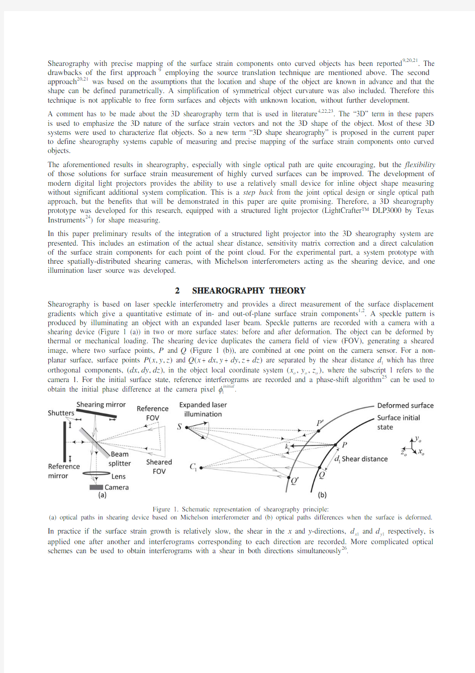
Shearography is based on laser speckle interferometry and provides a direct measurement of the surface displacement gradients which give a quantitative estimate of in- and out-of-plane surface strain components 1,2. A speckle pattern is produced by illuminating an object with an expanded laser beam. Speckle patterns are recorded with a camera with a shearing device (Figure 1 (a)) in two or more surface states: before and after deformation. The object can be deformed by thermal or mechanical loading. The shearing device duplicates the camera field of view (FOV), generating a sheared image, where two surface points, P and Q (Figure 1 (b)), are combined at one point on the camera sensor. For a non-planar surface, surface points (,,)P x y z and (,,)Q x dx y dy z dz are separated by the shear distance 1d which has three orthogonal components, (,,)dx dy dz , in the object local coordinate system (,,)o o o x y z , where the subscript 1 refers to the camera 1. For the initial surface state, reference interferograms are recorded and a phase-shift algorithm 25 can be used to obtain the initial phase difference at the camera pixel 1initial I .
Figure 1. Schematic representation of shearography principle:
(a) optical paths in shearing device based on Michelson interferometer and (b) optical paths differences when the surface is deformed. In practice if the surface strain growth is relatively slow, the shear in the x and y -directions, 1x d and 1y d respectively, is
applied one after another and interferograms corresponding to each direction are recorded. More complicated optical schemes can be used to obtain interferograms with a shear in both directions simultaneously 26.
When the surface is deformed, points P and Q move to their new positions, c P and c Q respectively, and signal interferograms are recorded to get the signal difference of phase 1I c . The surface deformation changes the length of the optical path between the laser located at S , the first camera located at 1C and aforementioned surface points 2. For a small amount of shear in the y -direction 1y d 11y d PC JJJJ G and
1y d PS JJJ G the change in optical path length causes the phase change 1I 'y where the subscript 1 refers to the camera 1. The phase change 1I 'y can also be calculated as a function of the surface strain components 2 (,,)u y v y w y w w w w w w : 11111112initial y y y x y z y k u y k v y k w y d S I I I O c ' w w w w w w , (1)
where 1initial y I and 1y I c are the reference and signal phase differences obtained at the camera 1 at the initial surface state and after the load, respectively, O is the laser wavelength, 111()x y z k k k are components of the sensitivity vector 1k J J G of the camera 1, that is the bisector between the illumination PS JJJ G and viewing 1PC JJJJ G directions: 111
PC PS k PS PC JJJJ G JJJ G J J G JJJ G JJJJ G . (2) In order to isolate the surface strain components, a multicomponent shearography instrument with at least three viewing directions (three cameras) needs to be used 4,5. The surface strain components (,,)u y v y w y w w w w w w for the shear yj d in the y -direction can be calculated 2,6 by processing the phase changes yj I ' obtained at each camera 1,2,3j : 111111111222
2222333333322I I O O I I S S I I aoaoaow w ''ao????????w w ' '????????????????w w ''????????
y y x y z y y y y x y z y y y y x y z y y u y d k k k d v y M d k k k d w y d k k k d , (3) where M is a sensitivity matrix of sensitivity vector components for each camera. The surface strain components in the x -direction (,,)u x v x w x w w w w w w can be calculated in the same way 4 replacing y by x in Equations (1) and (3).
3 3D SHAPE SHEAROGRAPHY
The proposed approach for surface strain measuring of curved objects by 3D shape shearography (Figure 2) is based on transferring shearography data (incl. object-system coordinate relation, phase maps and shear distances) from the shearography system with three shearing cameras to each point of the object surface in 3 main steps:
1. Inline object shape measurement (tasks 1.1-3, Subsection 3.1) to get a point cloud corresponding to the object
shape. This is a key step that matches the shape of the object together with the shearography system geometry. This matching is used for sensitivity matrix correction, shear estimation and strain mapping.
2. Estimation of the actual shear maps for each shearing camera (tasks 2.1-2, Subsection
3.2) mapped onto the curved surface required for accurate numerical interpretation of phase maps.
3. Conventional registration of the phase maps (task 3, Subsection 3.3) before and after surface deformation including phase shifting, filtering, unwrapping and zero order fringe tracking subtasks.
These steps have to be done for each point P of the point cloud that is of interest for strain calculation in order to obtain parameters needed for use in Equation (3).
It is important to mention that if the location of the object is fixed in relation to the system and the estimated shear amount is used for interferogram registration, the point P coordinates, the sensitivity matrix and shear maps are constant for each point, so the surface strain components depend only on the phase maps.
3.1 Cameras and projector geometric calibration and object shape measuring
In order to measure the shape of the surface, the cameras and the projector require geometric calibration. The well-known Zhang’s camera model 27 can be used for this purpose together with commonly used toolboxes 28,29. The projector can be calibrated using the same model, but acting as an inverse camera 30.
Figure 2. The approach for surface strain measurement of curved surfaces with 3D shape shearography.
The 3D shape shearography system geometry can be calibrated based on the reference optical paths of shearing cameras. The reference path is set by blocking the shutters in the shearing arm of each interferometer (Figure 1 (a)). The calibration of reference paths is acceptable in practice because the shearography principle introduces coordinate uncertainty within the shear distance. Also the orientation of the shear mirror is less stable than the reference one. Once the cameras and projector geometric calibration is done (as shown in Figure 3), four matrices of intrinsic j A and extrinsic [|]j j R T parameters for each camera and projector are known 27,29. They are used for coordinate transformation
from the homogeneous coordinates [1]T x y z of the point P in the world coordinate system to the homogeneous coordinates of a point j p in cameras image coordinate system [1]T u v :
[|]j j j j j s p A R T P , (4) where j R and j T are rotation matrix and translation vector, respectively, j s is a scale factor, 1,2,3,4j are the cameras
and projector internal numbers.
One of the cameras, e.g. the camera 1 coordinate system 111(,,)c c c x y z can be used as the shearography system master coordinate system (,,)c c c x y z . In this case, the relationship between the remaining cameras (2,3,4j ) coordinate systems, the projector and the camera 1 coordinate system is 31:
11101j j j c c cj R R T P P P
ao ????
. (5) The object local coordinate system (,,)o o o x y z has to be defined by a rotation matrix o R and a translation vector o T in order to relate measured surface strain components to the object localised data (e.g. from strain gauges or numerical modelling):
01o
o o c R T P P ao ????
. (6) A mechanical reference or some surface point of interest can be used as the origin of (,,)o o o x y z and the axes of symmetry or other object feature as coordinate axes.
Figure 3. Results of cameras geometry calibration together with
point cloud that corresponds to a cylinder specimen with projected fringe pattern.
The shape of the object can be measured with the common phase-shifting technique by projecting sinusoidal fringes onto the object 32 and presented as a point cloud of a data points in 3D space (Figure 3). Once the point cloud is generated and the relationship between the coordinate systems is known, the correction of a sensitivity matrix (Equation (3)) can be easily performed by simple use of coordinates for each point o P in (,,)o o o x y z and the system geometry 2,6 using Equations (2) and (3). Following this approach, a sensitivity matrix value has to be assigned as a property to each point of the cloud.
3.2 Shear estimation
As reported before 2,21, the shear angle of a shearing device may be not uniform within the field of view because of aberrations and possible misalignments, so the shear distance at a specific distance requires calibration. This task becomes more complicated when the shear is mapped onto a curved object because of the arising z coordinate component and difference in scale along cj z (Figure 1). It is proposed here to estimate the shear distance for each data point of the cloud by projecting it to each camera, identifying the shear in the image space of each camera and reprojecting it back onto the surface as depicted in Figure 4. The detailed explanation is given below.
Figure 4. Estimation of a shear map for existing 3D point cloud:
(a) shear projection and (b) intersection of the “sheared” ray with the object surface.
Known techniques for the estimation of the actual shear map by digital image correlation 33 in the image space (,)j j v u can be employed. A predefined speckle pattern can be projected onto the object by the projector. Three images for each
camera have to be taken, respectively, through the reference mirror (shear mirror is blocked), and through the shear mirror with shear applied sequentially in x and y -directions (reference mirror is blocked). Digital image correlation of the reference image of the speckle pattern with speckle pattern images with shearing in the x and y -directions gives an estimation of the shear distance for each pixel of each camera (e.g. pixel j q for pixel j p in Figure 4 (a)).
For each point P of the cloud the projection j p onto a camera
j (1,2,3j ) can be identified using Equation (4) (Figure 4 (a)). Assuming that j j p q is the shear amount in the image space for pixel j p estimated with digital image
correlation, a point sj Q can be defined in (,,)o o o x y z by inverting Equation (4) and performing an additional coordinate transformation from the camera j coordinate system to the object local coordinate system (,,)o o o x y z (Equation (6)): 111101011o
o j j j j j j s R T R R T A s q Q
aoao ao ????????????
, (7) where j s is an arbitrary nonzero value.
As the relationship between (,,)c c c x y z and (,,)o o o x y z is known (Equation (6)), ray j sj C Q JJJJJG can be defined in (,,)o o o x y z . The intersection of ray j sj C Q JJJJJG with the object surface at j Q can be found as the nearest to the ray point of the cloud (e.g.
i D in Figure 4 (b)), if the point cloud density is high. Other options to find j Q are to triangulate the intersection 34 within a
triangle 12i i i D D D or to parameterise the surface and solve the task parametrically 35. Once the intersection point j Q is found for each point of the cloud for the shear applied in x and y -directions, the projections of shear distance j PQ on the c x and c y axes can be found. These projections, estimated for each point and
camera 123(,,)x x x d d d and 123(,,)y y y d d d , are required for the calculation of the surface strain components (Figure 2,
Equation (3)).
3.3 Phase maps registration and surface strain component calculation
Phase maps I ' recorded before and after surface deformation have to be registered for shears applied in x and y -directions for each camera as described in Section 2. This may be done in a conventional way, that has been reported in details for 3D shearography systems with multiple viewing configuration 2-4,20.
In order to get absolute values of the surface strain components, the absolute values of the phase map I ' (Equation (1)) have to be determined. If the phase change exceeds the [0,2]S or [,]S S ranges during loading, the phase map has zones with phase jumps of 2S . A phase unwrapping procedure has to be performed to remove these phase jumps 2. However, this may introduce multiple 2S components and cause the loss of the absolute phase value. So the zero order fringe (zone of phase distribution corresponding to a zero surface displacement) has to be traced for absolute strain measurement 2,36. Once the absolute phase maps 123(,,)x x x I I I ''' and 123(,,)y y y I I I ''' for shear applied in x and y -directions are processed for each camera, they have to be transferred to become a cloud of data point to complete the set of properties that is required for the surface strain component calculation (Figure 2). The proposed approach for surface strain measuring of curved surfaces with 3D shape shearography is based on the point cloud. So a point of interest for strain characterisation P has to be projected to each camera using Equation (4) to identify the pixel coordinate (,)j j j p u v on the
camera sensor and to pick the values on the calculated phase maps (,)xj j j u v I ' and (,)yj j j u v I ' (1,2,3j ) for this pixel
as the properties of the projected point. Once this is done, the surface strain components (,,)u x v x w x w w w w w w and (,,)u y v y w y w w w w w w at the point P can be calculated using Equation (3).
4 EXPERIMENTAL EVALUATION
4.1 3D shape shearography system prototype
For the experimental evaluation of the proposed approach for surface strain measuring of curved surfaces, a 3D shape shearography system prototype was developed (Figure 5). It was based on an earlier reported one 37,38 with integrated structured light projector (LightCrafter? DLP3000 by Texas Instruments 24). Three spatially-distributed shearing cameras, the laser with beam expansion optics and the projector were placed in a cross configuration using an Alufix modular fixture system 39. Shearing cameras consist of Basler Pilot piA2400 cameras with Linos MeVis-C 1.6/25
imaging lenses and the shearing devices are based on Michelson interferometers 40,41. The cameras and the projector were calibrated in pairs as stereovision systems 28-30 in a volume of 200×150×150 mm (Section 3, Figure 3).
Figure 5. 3D shape shearography system prototype with calibrated configuration parameters.
As previously reported 20,21, the cylinder specimen, used as a test object, has a length of 400 mm and an external diameter of 190 mm. The specimen was mounted in front of the system at a distance of 500 mm and was loaded by internal pressure with a pump using oil. Several strain gauges were mounted on the specimen provide a reference values of the surface strain components u x w w and v y w w .
4.2 Experimental results
First, the shape of the specimen was measured as proposed in Subsection 3.1 with a five step Schwider-Hariharan phase-shifting algorithm 42. Sinusoidal fringes were projected onto a flat reference surface placed at a distance of 500 mm and the reference phase distribution was obtained through the reference optical path for each camera. Secondly, the fringes were projected onto the object. The difference in phase of projected fringes revealed the height map of the object. With regard to the system geometry (Figure 3), three point clouds for each camera-projector pair were generated and merged into one. The object local coordinate system (,,)o o o x y z was defined as shown in Figure 5. Then the actual shear distances were estimated for each point of the cloud as proposed in Subsection 3.2. The shear maps in the image space of the cameras was estimated by projecting a predefined speckle pattern by the projector and processing of images taken through the reference and sheared optical paths with 2D image correlation software 43. Further a simple criteria of the nearest point of the cloud to each projected ray was used for estimation of the actual shear.
During the measurements the specimen was loaded by an internal pressure of 1.0±0.1 MPa in a sequential mode 20 with steps of approximately 0.1 MPa. Such small load steps correspond to a phase change of less than 2S for reliable tracking of the zero order fringe. At each load step five phase shifted interferograms for shear x and y -directions were recorded and processed to give the difference of phase at each pixel of each camera 42. After that the total phase maps were calculated as a sum of all the steps. According to Subsection 3.3 six surface strain components were calculated for each point of the entire point cloud (Figure 6 (a-f)). Each figure is a 3D plot of a point cloud with a gray level corresponding to the local strain level. The measured area is close to 200×130 mm in the o o y x -plane. The measured surface strain components u x w w and v y w w that are commonly used for the assessment of stress-strain states are enlarged (Figure 6 (e, f)). The comparison of the surface strain components measured with 3D shape shearography and strain gauges is provided in Table 1.
Table 1. Comparison of experimental results obtained with 3D shape shearography and strain gauges.
The main experimental result is the uniformity of the surface strain components u x w w and v y w w (Figure 6 (e, f)). A relatively high mean difference (Table 1) between 3D shearography and strain gauges may be explained by a low absolute level of the measured strain and insufficient system calibration. Zones A (Figure 6 (e, f)) correspond to an area where one of the strain gauges was placed. Zone B (Figure 6 (f)) has an evidence of a wrapped phase occurred during one of the loading steps. Zone C (Figure 6 (f)) corresponds to a zone with a high specular reflection of the illuminating laser to the camera 2.
Figure 6. Surface strain components mapped onto the point cloud (a-f).
5 DISCUSSION
A new approach for the measurement of surface strain components of curved objects by 3D shape shearography has been proposed. This approach can also be applied to a flat surfaces, especially when the surface is not normal to the system and the shear distance changes due to difference in scale along the distance.
The proposed approach is based on a point cloud and particularly on a single point, that acts as a “carrier” of the shearography data (see point properties in Figure 2). A triangulated mesh can also be used, with a vertex or a face acting as the carrier , by following the same steps. Another option is to parametrically define the surface or use its CAD model. In this case, inline shape measuring with the projector can be used for estimation of the object orientation in the measuring system coordinate system. A realisation of the approach based on a multiple viewing shearography system with three shearing cameras and one illumination source was presented. It can however be adopted to a higher number of cameras or multiple illumination concept. An assumption was made when the actual shear distance was estimated (Figure 4 (a)) and the chord j PQ determined. This is applicable in practice, as the error of shear estimation (difference in length between chord j PQ and arc q j PQ ) is less than 5% when shear distance is 5 mm and local radius of curvature is 5 mm. In case of higher radiuses and smaller shear amounts, the error of local surface flattening is almost negligible.
6CONCLUSIONS
This paper covers practical questions of 3D shape shearography system development. The approach is based on the integration of a structured light projector into the 3D shearography system for inline shape measuring of the object. As a result, the actual shear distance along the curved object can be estimated, together with a correction of the sensitivity matrix for calculation of the surface strain components.
The proposed approach for surface strain measuring of curved objects by 3D shape shearography can improve the performance of shearography technique. The new ability to perform inspection of 3D and free form surfaces may open new applications and lead to practical solutions of new tasks in crucial fields such as aerospace (e.g. inspection of leading edges and nose cone of aircrafts), energy (e.g. turbine blades) and cultural heritage (e.g. sculptures). At the same time a higher accuracy of measurement of the surface strain components, mapped onto curved surfaces, may lead to better characterization of materials and more reliable detection of inner defects.
Experimental results obtained with a cylinder specimen prove the applicability of the approach, however, some improvements have to be done. The next steps of the research are to improve the calibration of cameras by pure multiple view calibration and to employ an additional viewing direction for robust absolute phase and consequently, absolute strain reconstruction44,45.
REFERENCES
[1] Hung, Y.Y., "Shearography: a new optical method for strain measurement and non-destructive testing," Opt. Eng. 21, 213391 (1982).
[2] Steinchen, W., Yang, L., [Digital Shearography], SPIE Press, Bellingham, Washington (2003).
[3] Francis, D., Tatam, R.P., Groves, R.M., "Shearography technology and applications: a review," Meas. Sci. Technol. 21, 102001, 29 (2010).
[4] James, S.W., Tatam, R.P., "Time-division-multiplexed 3D shearography," Proc. SPIE 3744, 394-403 (1999).
[5] Groves, R.M., James, S.W., Tatam, R.P., "Multi-component shearography employing four measurement channels," Proc. SPIE 4933, 135-140 (2003).
[6] Francis, D., James, S.W., Tatam, R.P., "Surface strain measurement using multi-component shearography with coherent fibre-optic imaging bundles," Meas. Sci. Technol. 18(11), 3583 (2007).
[7] Groves, R.M., James, S.W., Tatam, R.P., "Strain measurement in curved industrial components using multicomponent shearography," Proc. SPIE 4398, 216 (2001).
[8] Stetson, K.A., "Use of sensitivity vector variations to determine absolute displacements in double exposure hologram interferometry," Appl. Opt. 29, 502-504 (1990).
[9] Groves, R.M., James, S.W., Tatam, R.P., "Shape and slope measurement by source displacement in shearography," Opt. Laser. Eng. 41(4), 621-634 (2004).
[10] Shang, H.M., Quan, C., Tay, C.J., and Hung, Y.Y., "Generation of carrier fringes in holography and shearography," Appl. Opt. 39, 2638-2645 (2000).
[11] Blain, P., Michel, F., Piron, P., Renotte, Y., Habraken, S., "Combining shearography and interferometric fringe projection in a single device for complete control of industrial applications," Opt. Eng. 52(8), 084102 (2013).
[12] Shang, H.M., Hung, Y.Y., Luo, W.D., Chen, F., "Surface profiling using shearography," Opt. Eng., 39(1), 23-31 (2000).
[13] Hack, E.K., Riner, M., "3D ESPI and 3D shearography measurements applied to NDT and FEM analysis validation for industrial quality control," Proc. SPIE 4398, 155 (2001).
[14] Groves, R. M., Li, A., Liu, X., Hackney, S., Peng, X., Osten, W., "2.5D virtual reality visualisation of shearography strain data from a canvas painting," Proc. SPIE 7391, 739109 (2009).
[15] Berger, R., Huber, R., "Shearography as an Industrial application including 3D result mapping," Proc. ECNDT, P79 (2006).
[16] Berger, R., "Quality control with shearography and 3D-digitizing," Proc. ECNDT, P79 (2010).
[17] Chen, X., "Computational and experimental approach for non-destructive testing by laser shearography," PhD diss., University of Zaragoza, Spain (2014).
[18] Chen, X., Khaleghi, M., Dobrev, I., Tie, W., Furlong, C., "Structural health monitoring by laser shearography: experimental and numerical investigations," Experimental and Applied Mechanics (6). Springer International Publishing, 149-155 (2015).
[19] Chen, X., Khaleghi, M., Dobrev, I., Furlong, C., "Non-destructive testing (NDT) by laser shearography and fringe projection," Proc. SES/ASME-AMD (2013).
[20] Goto, D.T., Groves, R.M., "A combined experimental with simulation approach to calibrated 3D strain measurement using shearography," Proc. SPIE 7387, 77871J (2010).
[21] Goto, D.T., Groves, R.M., "Error analysis of 3D shearography using finite-element modelling," Proc. SPIE 7718, 771816 (2010).
[22] James, S.W., Tatam, R.P., "3D shearography for surface strain analysis," Proc. SPIE 3783, 247 (1999).
[23] Molimard, J., Dandach, W., Picart, P., "Direct strain and slope measurement using 3D DSPSI," Proc. Photomechanics (2013).
[24] DLP? LightCrafter? Evaluation Module, https://www.360docs.net/doc/8d18864920.html,/tool/DLPLIGHTCRAFTER (2015).
[25] Dorrio, B.V., and Fernandez J.L., "Phase-evaluation methods in whole-field optical measurement techniques," Meas. Sci. Technol. 10, R33-R35 (1999).
[26] Siebert , T., Schmitz, B., "New shearing setup for simultaneous measurement of two shear directions," Proc. SPIE 3637, 225 (1999).
[27] Zhang, Z., "Flexible camera calibration by viewing a plane from unknown orientations," The Proceedings of the Seventh IEEE International Conference on Computer Vision, 1, 666-673 (1999).
[28] Bouguet, J.Y., "Camera calibration toolbox for MATLAB" (2004).
[29] Heikkila, J., Silvén, O., "A four-step camera calibration procedure with implicit image correction," In Computer Vision and Pattern Recognition, Proceedings IEEE Computer Society Conference, 1106-1112 (1997).
[30]
Falcao, G., Hurtos, N., Massich, J., Fofi, D., "Projector-Camera Calibration Toolbox," https://www.360docs.net/doc/8d18864920.html,/p/procamcalib (2009).
[31] Hartley, R., Zisserman, A., [Multiple view geometry in computer vision], Cambridge University Press. (2003).
[32] Zhang, S., "Recent progresses on real-time 3D shape measurement using digital fringe projection techniques," Optics and Lasers in Engineering, 48(2), 149-158 (2010).
[33] Ng, T.W., "Shear measurement in digital speckle shearing interferometry using digital correlation," Opt. Comm., 115(3), 241-244 (1995).
[34] M?ller, T., Trumbore, B., "Fast, minimum storage ray/triangle intersection," ACM SIGGRAPH Courses (2005).
[35] Toth, D.L., "On ray tracing parametric surfaces," ACM SIGGRAPH Computer Graphics 19.3, 171-179 (1985).
[36] Groves, R.M., James, S.W., Tatam, R.P., "Investigation of the fringe order in multi-component shearography surface strain measurement," In Fringe 2005, 212-216 (2006).
[37] Anisimov, A.G., Müller, B., Sinke, J., Groves, R.M., "Strain characterization of embedded aerospace smart materials using shearography," Proc. SPIE 9435, 943524 (2015).
[38] Müller, B., Anisimov, A.G., Groves, R.M., Sinke, J., "Thermal strains in heated fibre metal laminates", Proc. ETNDT6 (2015) (accepted, to be published in June 2015).
[39] Alufix modular fixture system, http://www.horst-witte.de/en/products/modular-fixturing-systems/alufix-classic.php (2015).
[40] Basler pilot family, https://www.360docs.net/doc/8d18864920.html,/en/products/area-scan-cameras/pilot (2015).
[41] LINOS Machine Vision Lenses, https://www.360docs.net/doc/8d18864920.html,/en/Precision-Optics/LINOS-Machine-Vision-Solutions/LINOS-Machine-Vision-Lenses/MeVis-C.html (2015).
[42] Hariharan, P., Oreb, B.F., and Eiju, T., "Digital phase-shifting interferometry: a simple error-compensating phase calculation algorithm," Appl. Opt. 26, 2504-2506 (1987).
[43] Lemmen, H.J.K., Alderliesten, R.C., Benedictus, R., Hofstede, J.C.J., Rodi, R., "The power of digital image correlation for detailed elastic-plastic strain measurements," Proc. EMESEG, 73-89 (2008).
[44] Siebert, T., Splitthof, K., Ettemeyer, A., "A practical approach to the problem of the absolute phase in speckle interferometry," J. Holography and Speckle 1(1), 32-38 (2004).
[45] Charrett, T., Francis, D., Tatam, R., "Quantitative shearography: error reduction by using more than three measurement channels," Appl. Opt. 50, 134-146 (2011).